Abstract
A simple and efficient bottom-roller axle intersections approach for judging the omnidirectional mobility of the Mecanum wheel configuration is proposed and proved theoretically. Based on this approach, a sub-configuration judgment method is derived. Using these methods, on the basis of analyzing the possible configurations of three and four Mecanum wheels and existing Mecanum wheel configurations of robots in practical applications, the law determining wheel configuration is elucidated. Then, the topological design methods of the Mecanum wheel configurations are summarized and refined, including the basic configuration array method, multiple wheels replacement method, and combination method. The first two methods can be used to create suitable multiple-Mecanum-wheel configurations for a single mobile robot based on the basic Mecanum wheel configuration. Multiple single robots can be arranged by combination methods including end-to-end connection, side-by-side connection, symmetrical rectangular connection, and distributed combination, and then, the abundant combination configurations of robots can be obtained. Examples of Mecanum wheel configurations design based on a symmetrical four-Mecanum-wheel configuration and three centripetal configurations using these topological design methods are presented. This work can provide methods and a reference for Mecanum wheel configurations design.
1. Introduction
Each Mecanum wheel has three degrees of freedom of motion in a plane [1,2], so a mobile robot system consisting of three or more than three Mecanum wheels can achieve omnidirectional motion in a plane only through the coordination of direction and rotation speed of wheels without the assistance of an auxiliary steering mechanism. Because of the simple structure and good motion flexibility, omnidirectional mobile robots with Mecanum wheels are widely used in various fields. According to application needs in different fields, a variety of Mecanum wheel configurations can be designed to develop various omnidirectional mobile robots. Some service robots usually adopt three or four-Mecanum-wheel configurations [3,4]. In the industrial field, an AGV (automated guided vehicle) with four Mecanum wheels, a kind of omnidirectional mobile robot, is also widely used [5,6,7,8]. For transporting large-scale equipment or components, a robot platform with multiple Mecanum wheels [9,10,11] or multiple-Mecanum-wheeled robot platforms are used cooperatively [12,13]. In order to design an omnidirectional mobile robot, it is necessary to select a reasonable Mecanum wheel configuration for the robot. However, not all combinations of Macanum wheels can implement omnidirectional motion, and the arrangement of Mecanum wheels also influences the mobility performance of the robot [14]. Therefore, designing a reasonable configuration of Mecanum wheels constitutes the most basic and important technology problem in the design of omnidirectional mobile robots. Firstly, these configurations must satisfy the conditions of realizing omnidirectional movement. Secondly, motion performance, controllability, and structural rationality of these configurations must be evaluated in order to select the optimal Macanum wheel configuration.
Some researchers have paid attention to the study of Mecanum wheel configurations. The kinematics and dynamics of a Mecanum-wheeled mobile robot form the basic premise to judge the robot to achieve omnidirectional movement in theory. Muir et al. [15,16] introduced a methodology for the kinematic modeling of wheeled mobile robots, studied an omnidirectional wheeled mobile robot with four Mecanum wheels, and derived the kinematic model of roller angle dead reckoning robot position wheel slip. Angeles [17] deduced a general kinematics model of the Mecanum-wheeled omnidirectional mobile system by vector method, and gave kinematics and dynamics equations of three-wheel and four-wheel robots, respectively. Campion [18] used a matrix transformation method to study the mobility characteristics of the robot under constraints, gave a unified description of modeling of a wheeled mobile robot, and deduced the kinematics equation of the three-wheeled robot. Gracia and Tornero [19,20] described the singular and heterogeneous types of mobile robots based on Mecanum wheels and Castor wheels using a descriptive geometry method, established the kinematics model of omnidirectional mobile robots under sliding conditions, and further established the Lagrange dynamics model. Zhang and Wang [21,22] analyzed the steering motion of a Mecanum-wheeled omnidirectional mobile platform, and established a control system model and dynamic model in MATLAB and RecurDyn software, respectively. Using joint simulation, the anisotropic motion characteristics of a mobile platform with different slip rates were obtained. Wang and Chang [23,24] analyzed the condition of omnidirectional motion of a Mecanum-wheeled mobile system and found that the Jacobian matrix of inverse kinematics velocity is a column full rank, discussed the possible singularities and solutions in motion, and showed six types of Mecanum wheels layouts and determined the four best Mecanum wheel layouts. Mishra et al. [25] proposed 10 possible configurations of the omnidirectional mobile robot with four Mecanum wheels. Gao et al. [26] studied a type of three-Mecanum-wheel omnidirectional mobile robot with symmetrical and concentric layout structure, and the motion simulation of the three-Mecanum-wheeled platform is compared with that of the symmetrical four-Mecanum-wheeled mobile robot platform. Zhang et al. [27] studied the three- and four-Mecanum-wheeled concentric layouts and analyzed the influence of the angles between wheel axes for a centered layout. He et al. [14] studied the two most used arrangement modes of Mecanum wheels, Type-X and Type-O, and used the inverse velocity Jacobian matrix of the arrangement to judge whether a vehicle can fulfill omnidirectional movement. The main contributions of these studies on wheel configuration include: (1) the method of establishing a kinematics equation of an omnidirectional mobile robot is proposed; (2) the method of judging omnidirectional mobility by rank of the Jacobian matrix of inverse kinematics is obtained; (3) the possible configuration of three or four Mecanum wheels is summarized and analyzed and compared. However, when using an inverse kinematics Jacobian matrix to analyze a multiple-Mecanum-wheeled mobile robot system, the calculation process is complex. Previous studies have not systematically summarized multiple-Mecanum-wheel (more than four wheels) configurations, and have not explicitly proposed a method to obtain the wheel configurations for omnidirectional mobile robots with more than four Mecanum wheels. This study explores a simple and efficient method to judge whether the wheel configurations possess omnidirectional mobility. On this basis, the common wheel configurations are judged and analyzed, the law of wheel configurations is explored, and the topological design methods of wheel configurations for an omnidirectional mobile robot are summarized and refined.
This paper is organized as follows: In Section 2, on the basis of studying the kinematic constraints of a single Mecanum wheel in a mobile system, the kinematics model of an n-Mecanum-wheeled mobile robot is further deduced. In Section 3, the relationship between the intersections of bottom-rollers axles of any three Mecanum wheels and the column rank of the Jacobian matrix of inverse kinematics of the mobile robot is established, and a bottom-rollers axles intersections approach for judging the omnidirectional mobility of Mecanum wheel configurations is proposed and proved theoretically, which is a simple and efficient geometric method. In Section 4, the four-Mecanum-wheel configurations are judged by using a bottom-rollers axles intersections approach, and the optimal four-Mecanum-wheel configuration is selected through comprehensive analysis and theoretical verification. In Section 5: firstly, the above method is used to judge the omnidirectional motion of a combined configuration consisting of two four-Mecanum-wheel configurations, and then the sub-configuration judgment method, which can be extended to N sub-configuration combinations is obtained. Secondly, this judgment method is used to analyze the Mecanum wheel configurations and combination configurations for common omnidirectional mobile robots, and clarify the law determining wheel configuration. Finally, the topological design methods of the Mecanum wheel configurations are summarized and refined, including the basic configuration array method, multiple wheel replacement method and combination method. Furthermore, based on the symmetrical four-Mecanum-wheel configuration, the Mecanum wheel configurations are generated by using the topological design methods.
2. Kinematics Model of an Omnidirectional Mobile Robot with n Mecanum Wheels
2.1. Mecanum Wheel Configurations of the Single Omnidirectional Mobile Robot
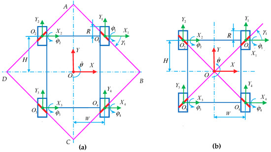
For an independent Mecanum-wheeled mobile robot, the wheel configurations can be mainly divided into two categories: centripetal configuration and symmetrical rectangular configuration [24], as shown in Figure 1. In Figure 1, the Mecanum wheel is represented by a rectangle with an oblique line in the middle, in which the oblique line represents the bottom roller that contacts with the ground. In the former configuration, the axles of all wheels intersect at the same intersection point, as shown in Figure 1a. In Figure 1a, the centerline of the mobile robot coordinate system and wheel local coordinate system is collinear with coordinate axis . In order to balance the load of each wheel, the wheels are evenly distributed in a 360° circumference. This centripetal configuration of an omnidirectional mobile robot usually composes of three [1,26] or four [27] Mecanum wheels. In the symmetrical rectangular configuration in Figure 1b, the Mecanum wheels are symmetrically arranged on both sides of the line going through the center of the robot, and the overall structure is rectangular. Based on the study of the kinematics constraints of a single Mecanum wheel, the kinematics model of an n-Mecanum-wheel mobile robot can be further derived, and then the omnidirectional motion characteristics of the mobile systems can be analyzed.
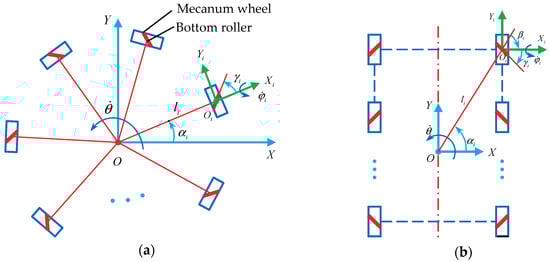
Figure 1.
Wheel configurations of the single-Mecanum-wheeled robot: (a) centripetal configuration; (b) symmetrical rectangular configuration.
2.2. Kinematics Constraint Model of a Single Mecanum Wheel and Kinematics Model of an n-Mecanum-Wheel Robot
The kinematics research of the Mecanum wheel is similar to that of a traditional wheeled mobile system. The kinematics model of the Mecanum-wheel mobile system can also be built by a bottom-up process. Each of the relatively independent Mecanum wheels contributes to the motion of the system and is relatively constrained by the motion of the system. Because the Mecanum wheels are installed on the chassis of a mobile system, the kinematic constraints of each wheel can be combined to describe the kinematic constraints of the whole mobile system.
In this section, the kinematic constraints of a single Mecanum wheel are studied first, and then, the linear mapping relationship between the velocity of the mobile system and the velocity of a single wheel is obtained. Then, the kinematic constraints of each wheel are combined to describe the kinematic constraints of the entire mobile system.
In order to reduce the difficulty of system kinematics modeling, several assumptions are usually introduced to discuss the motion constraint relationship of wheels under ideal conditions. (1) Assuming that the whole mobile robot, especially the wheels, is rigid, it will not undergo mechanical deformation; (2) the entire range of motion is confined to a 2D plane, ignoring the impact of irregular ground; (3) ignoring the factor of rollers slipping, that is, the roller has enough friction with the ground; (4) assuming that the contact point between the roller and the ground is located directly below the wheel center. Based on the above assumptions, the kinematic constraints of a single Mecanum wheel will be derived by a vector method [17] and matrix transformation method [18].
(a) Vector Method
In order not to lose generality, a mobile robot consisting of n Mecanum wheels is designed, in which the i-th wheel is mounted on the body at a certain angle, as shown in Figure 2. R and r are the radius of the wheel and the radius of the roller, respectively; is the center of the i-th wheel; represents the direction passing through the wheel center and perpendicular to the ground; is the center of the roller contacting the ground, is the contact point between the roller and the ground, according to the hypothesis, both of them are under at the same time; represents the direction passing through the roller center and perpendicular to the ground. and represent the rotation axis direction of an active Mecanum wheel and passive roller, respectively. The two angular velocity vectors are and , and and constitute the right-handed Cartesian coordinate system , and constitute the right-handed Cartesian coordinate system . is used to describe the relative installation orientation of the origin of the body coordinate system and the center of the wheel; the angle between the axis and the is , which is defined as the installation attitude angle of the local coordinate system of the wheel; the velocity of the motion center is in the current state, and the angle between the and the axis is ; is the rotation angular velocity of the system when moving in the plane. The angle between the projection of and on the plane is the tilt angle () of the roller.
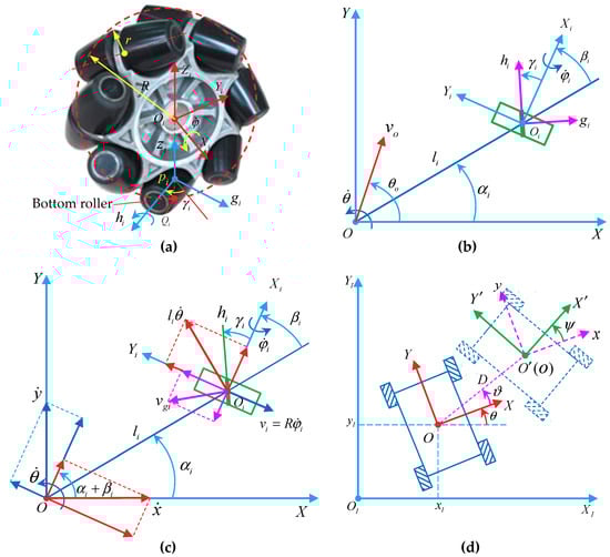
Figure 2.
Kinematic constraints of a Mecanum wheel and the coordinate systems of a mobile system: (a) structural principle of a Mecanum wheel; (b) Kinematic constraints diagram of a Mecanum wheel on the robot using a vector method; (c) Kinematic constraint diagram of a Mecanum wheel using a matrix transformation method; (d) Location of the mobile robot in the global coordinate system and the relationship regarding position between two local coordinate systems.
According to the above definition, the motion relationship between the active wheel and the passive roller can be expressed by the formula
In this formula, is the velocity vector of the center of the i-th wheel; is the velocity vector of the roller in contact with the ground; is the relative velocity vector of point and .
and represent the rotational angular velocity vectors of the active wheel and the passive roller, respectively, as
then
From Formulas (1) and (3), we obtain
If the known moving system moves in the plane, the relation between the wheel center and the origin of the body coordinate system can be expressed as
In this formula,, which means that the vector is rotated 90 degrees counterclockwise.
The following formula can be obtained from Formulas (4) and (5).
According to the definition of vectors, we can obtain
Since the roller rotates passively, its angular velocity is an uncontrollable variable. According to the calculation result defined by the vector in Formula (7), multiplying the vector at the same time on both sides of Formula (6), the subformula containing the term can be eliminated.
Then, the inverse kinematics equation of the i-th Mecanum wheel is
Given the kinematic constraint equation of any Mecanum wheel in the plane, the inverse kinematics equation of the omnidirectional motion system composed of n Mecanum wheels whose radii are R can be expressed as
In the formula, is the angular velocity matrix of the wheel; is the Jacobian matrix of the inverse kinematics velocity of the mobile robot, including the matrix of tilt angle of rollers and the matrix of wheel installation orientation; t is the rotation matrix of the mobile system.
In this section, three coordinate transformation matrices—including translation transformation, rotation transformation, and composite transformation—are introduced, which form an important theoretical basis for studying the kinematics constraints of mobile systems. The kinematic constraints of a single Mecanum wheel are derived by the vector method. On this basis, the general kinematic model of the mobile system composed of n Mecanum wheels is obtained.
(b) Matrix Transformation Method
Matrix transformation is another common method for kinematics analysis of a wheeled mobile system, which can be used for kinematics modeling of an omnidirectional wheel. The precondition of using this method to study a single Mecanum wheel still needs to satisfy the above assumptions and start with the study of rolling and sliding constraints of the wheel. The motion constraints of one Mecanum wheel are shown in Figure 2c [23,24].
Based on the above assumptions, the motion between the roller and the ground satisfies the condition of pure rolling, the contact point between the roller and the ground does not slip, and the instantaneous velocity is 0. According to the constraints of rolling and sliding, the following formulas can be obtained
In the formula, is the motion state of the mobile system in its own local coordinate system; is the central velocity of the roller contacting the ground on the i-th Mecanum wheel.
Because the rollers rotate passively, the velocity of motion is an uncontrollable variable, which is usually not taken into account. By eliminating from Formula (11), we obtain
The inverse kinematics matrix equation of any Mecanum wheel is
The motion state in a local coordinate system can be mapped to a global coordinate system, as shown in Figure 2d, which is expressed as
where
3. Bottom-Roller Axle Intersections Approach for Judging Robot’s Omnidirectional Mobility
3.1. Conditions for Omnidirectional Motion of a Mecanum-Wheeled Mobile Robot System
If the Mecanum wheel configuration of a robot cannot achieve omnidirectional movement, it will lose practical value. Therefore, it is necessary to study the relationship between the wheel configuration and the realization of the omnidirectional movement of the mobile system. The inverse kinematics velocity Jacobian matrix of a mobile system consisting of Mecanum wheels is . According to the kinematics principle of the robot, if the Jacobian matrix is a column full rank matrix, that is, , the mobile robot system will have three degrees of freedom in the plane. The Jacobian matrix is written into the form of block matrix, which is expressed as
Assuming that the third-order square matrix is an invertible matrix, i.e., . According to the elementary transformation theory of a matrix, the simplest matrix of the reversible matrix is the unit matrix of the third order.
Extending this conclusion to the whole Jacobian matrix , then
Therefore, in the mobile system composed of n Mecanum wheels, the system can achieve omnidirectional movement, as long as the inverse kinematics velocity Jacobian matrix of any three wheels is a column full rank matrix.
According to the basic theory of coordinate transformation, when the coordinate system changes, the description of the motion state of the mobile system will change accordingly, and the Jacobian matrix of its inverse kinematics velocity will change, which can be expressed by the following formula
where, is the inverse kinematics velocity Jacobian matrix in the new coordinate system; is the inverse kinematics velocity Jacobian matrix in the original coordinate system; is reversible square matrix of the third order, then, .
Let , given is an invertible matrix, , the inverse matrix exists, then .
According to the properties of matrices—the rank of the product of the matrices is not greater than the rank of each matrix—the following formulas can be derived
According to the above formula, the rank of the product of and is equal to the rank of , that is
The above deduction shows that the change of the coordinate system will not change the rank of the Jacobian matrix in the mobile system. Under certain circumstances, the appropriate coordinate system can be selected to simplify the calculation of the Jacobian matrix rank.
3.2. Relation Between the Roller Axle Intersection Points Number on Three Mecanum Wheels and the Column Rank of the Jacobian Matrix
The two straight lines in the plane have three positional relations: parallel, intersection, and coincidence, and the corresponding number of intersections is 0, 1, and infinite. In a plane, the number of intersections of three roller axles on three Mecanum wheels is 0, 1, 2, 3, and infinite. Next, we will discuss the relationship between the number of intersections and the rank of the Jacobian matrix. That is, the relationship between Mecanum wheel configurations and omnidirectional motion is studied. In this paper, infinite intersection points are specialized into one intersection point, which is discussed in detail below.
3.2.1. No Intersection of the Three Bottom-Rollers Axles
In Figure 3, the axles of any two bottom-rollers are parallel to each other, and the number of intersections is 0. The mobile system coordinate is established by choosing any point on one of the roller axles as the origin, and then the local wheel coordinate systems () are established in counterclockwise order. is used to describe the positional state of each wheel relative to the coordinate system of the mobile robot system. The radius of the Mecanum wheel is R, and the tilt angle of rollers of each Mecanum wheel is . The relationship of the parameters is shown in Table 1.
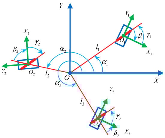
Figure 3.
Wheel configuration of the mobile robot with three Mecanum wheels whose bottom-roller axles are parallel to each other.

Table 1.
Relationship between the parameters of the three Mecanum wheels in Figure 3.
The origin of the coordinate system is located on the bottom-roller axle of wheel , and the axles of any two rollers are parallel to each other, so the following relationship is established as
The tilt angles of the axles of the three rollers are the same, so let .
From Formulas (10), (13), and (21), the inverse kinematics velocity Jacobian matrix of the system is obtained as
where
The roller tilt angle matrix is a reversible square matrix of the third order. The rank of inverse kinematics velocity Jacobian matrix depends on the matrix that describes the installation orientation information of the Mecanum wheel, that is, .
According to Formula (22), the following formula can be obtained.
According to the multiplication theorem of the determinant, we obtain
According to the above analysis, in a mobile system composed of three Mecanum wheels, if the axles of rollers are parallel to each other and the number of intersection points is 0, then the mobile system has singularity. The inverse kinematics velocity Jacobian matrix of the system is not a column full rank matrix, so the mobile system cannot achieve omnidirectional movement.
3.2.2. The Axles of the Three Bottom-Rollers Intersect at One Point
In Figure 4, the axles of the three bottom-rollers intersect at one point, and the coordinate system of the mobile robot system is established with the intersection point as the origin, and the local wheel coordinate systems are established in a counterclockwise order. The relationship of the parameters is shown in Table 2.
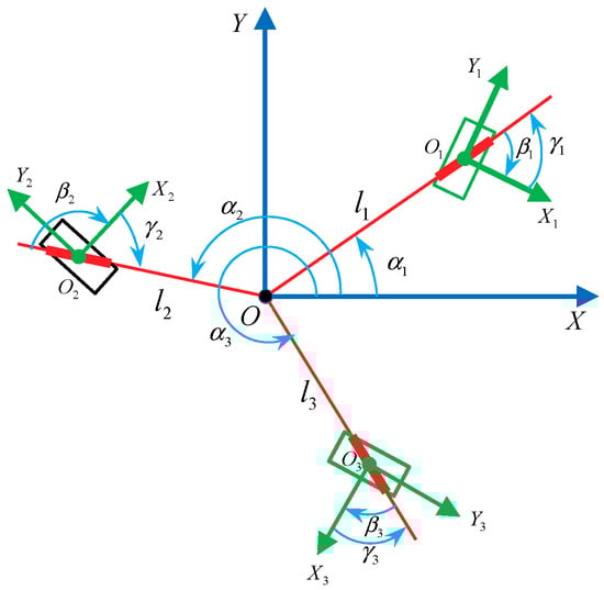
Figure 4.
Wheel Configuration of the mobile robot with three Mecanum wheels whose bottom-roller axles intersect at one point.
Table 2.
Relationship between the parameters of the three Mecanum wheels in Figure 4.
The matrix M of wheel installation orientation is
The values of the third column of matrix M are all 0, then,
then,
In the mobile system composed of three Mecanum wheels, if the axles of the three bottom-rollers intersect at one point, the mobile system has singularity, and the inverse kinematics velocity Jacobian matrix does not satisfy the condition of a column full rank matrix; therefore, the mobile system cannot achieve omnidirectional motion.
If the axles of any two bottom-rollers coincide with each other or the axles of three bottom-rollers coincide with each other, it can be concluded that the axles of two bottom-rollers intersect at one point, which also satisfies the inference that the axles of three bottom-rollers intersect at one point. There are four configurations of three Mecanum wheels whose axles intersect at one point, three of which have collinear roller axles.
3.2.3. The Axles of the Three Bottom-Rollers Intersect at Two Points
According to the hypothesis, when two roller axles intersect at one point, the other roller axe must be parallel to one of the roller axles. As shown in Figure 5, if any two roller axles coincide, the result will inevitably be transformed into the case of axles intersecting at one point. The coordinate system is established by arbitrarily choosing one of the intersections as the origin , and the local wheel coordinate system () is also established in counterclockwise order. The relationship of the parameters is shown in Table 3.
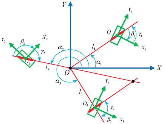
Figure 5.
Wheel configuration of the mobile robot with three Mecanum wheels whose roller axles intersect at two points.
Table 3.
Relationship between the parameters of the three Mecanum wheels in Figure 5.
The system coordinate system is established at the intersection of the roller axles of wheel and wheel , then we can obtain
The roller axles of wheels and are parallel to each other, and the following relations are established
Thus, the matrix M can be obtained ad
The determinant of matrix M is
Combining with the discussion in Section 3.2.2, the roller axle of wheel does not coincide with the straight line , so or , then, .
Because the roller axles of wheels and intersect at one point, or and , then, the following is established
then,
In the mobile system consisting of three Mecanum wheels, if the axles of the three bottom-rollers intersect at two points, there is no singularity in the system, and the Jacobian matrix of the inverse kinematics velocity is a column full rank matrix. The mobile system can realize omnidirectional movement in the plane.
3.2.4. The Axles of the Three Bottom-Rollers Intersect at Three Points
When the axles of the three bottom-rollers intersect at three points, no two axles of the bottom-rollers can be parallel or coincide with each other, as shown in Figure 6. The coordinate system is established by arbitrarily selecting one of the intersections as the origin. The relationship of the parameters is shown in Table 4.
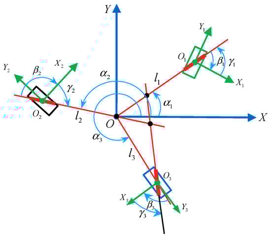
Figure 6.
Configuration of mobile robot with three Mecanum wheels whose roller axles intersect at three points.
Table 4.
Relationship between the parameters of the three Mecanum wheels in Figure 6.
The coordinate system is established at the intersection point of roller axles of wheel and wheel . The following formula can be obtained
The matrix M can be obtained
The determinant of matrix M is
Roller axles of wheel and wheel intersect at one point, (); therefore, . The value is substituted into Formula (35), we can obtain
then,
In a mobile system consisting of three Mecanum wheels, if the axles of the three bottom-rollers intersect at three points, there is no singularity in the system, and the Jacobian matrix of the inverse kinematics velocity satisfies the column full-rank condition, and the mobile system can achieve omnidirectional motion in the plane.
According to the deduction of Formula (17) and the analysis results of the number of intersection points mentioned above, the condition for the omnidirectional motion of the mobile system composed of multiple Mecanum wheels (three wheels or more) is that any three axles of bottom-rollers in contact with the ground in three Mecanum wheels intersect at two or three points, which can be called a ‘bottom-roller axle intersections approach. Table 5 illustrates the three-Mecanum-wheel configurations of the omnidirectional mobile robot and shows the relationship between the number of intersection points and the column full rank. Based on these illustrations, we can quickly judge whether the mobile system can achieve omnidirectional movement using only wheel configurations.
Table 5.
Three-Mecanum-wheel configurations of the omnidirectional mobile robot.
3.3. Three-Mecanum-Wheel Configurations of the Mobile Robot
In order to balance the load, the three-wheel configuration usually adopts a circular array arrangement. The common three-Mecanum-wheel configurations include a centripetal circular array configuration [26], a non-centripetal circular array configuration [1], and a star-type circular array configuration, as shown in Figure 7a–c, respectively. Mecanum wheels in three-wheel configurations usually have the same structure, whose rollers have the same inclination. Judging by the bottom-roller axle intersections approach, these configurations all have omnidirectional mobility performance. The wheels in the three-wheel configuration are, typically, special Mecanum wheels whose rollers’ axles are orthogonal to the hub axle. These are known as omniwheels, transwheels, or multidirectional wheels, as shown in Figure 7f. In this article, we use an orthogonal Mecanum wheel to name this kind of wheel. The two typical orthogonal Mecanum wheel configurations are the centripetal circular array configuration [18,28,29] and T-configuration, as shown in Figure 7d,e, respectively. The configuration in Figure 7d is a rotational symmetry configuration, and this configuration is often used for indoor mobile service robots and light-duty handling robots. In this article, the orthogonal Mecanum wheel configurations are not studied in depth.
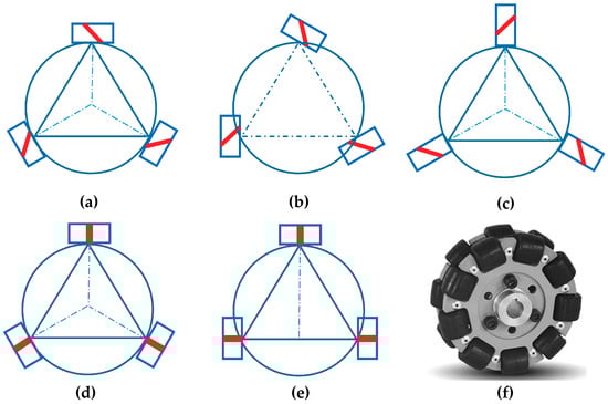
Figure 7.
Three-Mecanum-wheel configurations: (a) centripetal circular array configuration; (b) Non-centripetal circular array configuration; (c) star-type circular array configuration; (d) centripetal circular array configuration of orthogonal Mecanum wheels; (e) T-configuration of the orthogonal Mecanum wheels; (f) an orthogonal Mecanum wheel.
4. Symmetrical Wheel Configurations of the Four-Mecanum-Wheel Mobile Robot
4.1. Judging the Four-Mecanum-Wheel Configurations by a Bottom-Roller Axle Intersections Approach
At present, the mobile robot with four Mecanum wheels is the most popular configuration in both scientific research and industrial application. There are many possible wheel configurations for the four-Mecanum-wheel robot [23,25,30], some of them are illustrated in Figure 8. In Figure 8, the inclined line on the wheel in the figure represents the inclined direction of roller in contact with the ground. Figure 8a–j show 10 rectangular configurations of four wheels that are arranged at the corner and whose axles are parallel to the centerline of robot. Figure 8k–n show four possible centripetal configurations of four wheels. Figure 8o shows a centripetal circular array configuration of four omniwheels. In the configurations (a), (f), and (k), any three roller axles are parallel to each other or coincide with each other. The number of intersection points of the three roller axles is 0 or 1 (the overlapping axles are considered to intersect at one point). The column ranks of the Jacobian matrix of these configurations are 2. These configurations obviously cannot achieve omnidirectional movement. In the wheel configurations (b)–(e), (g)–(j), and (l)–(n), the axles of the bottom-rollers of three wheels intersect at two points, so the Jacobian matrices of these wheel configurations are column full-rank matrices. In theory, these configurations can achieve omnidirectional movement in the plane.
Figure 8.
Four-Mecanum-wheel configurations: (a)–(j) rectangular configurations of four wheels that are arranged at the corner and whose axles are parallel to the centerline of the robot; (k)–(n) centripetal configurations of four Mecanum wheels; (o) centripetal circular array configurations of four orthogonal Mecanum wheels.
In practical applications, besides satisfying the conditions of the column full rank of the Jacobian matrix, the configuration also needs good operability and driving performance. Wheel configurations (b), (c), (d), (g), (h), (i), (l), and (m) can satisfy the conditions of omnidirectional motion, but the symmetry and the driving performance of the mobile system is poor. Considering the influence of dynamic factors, such as friction and moment of inertia, in actual operation, there will be a large deviation in the motion. Therefore, these configurations are generally not used. In addition, if the centers of four wheels in the configuration (j) form a square, the axles of the three bottom-rollers intersect at the one point, the column rank of Jacobian matrix in these configurations will change from 3 to 2, and it is no longer an omnidirectional mobile system. Configuration (n) has omnidirectional mobility, but the motion friction component of the configuration cannot offset itself in the course of movement, and there is a tendency to rotate in situ. Configuration (o) is the configuration (n) using orthogonal Mecanum wheels, mostly for small robotic mobile platforms. The symmetry of wheels configurations (e) and (j) is the best among these wheel configurations that can achieve omnidirectional motion. However, when rotating on the spot, the mobile robot system with the configuration (j) has a small driving torque and a weak driving effect. Therefore, the configuration (e) is the optimal configuration of a four-Mecanum-wheel system. The characteristics of the Mecanum wheel configurations in Figure 8 are summarized in Table 6.
Table 6.
Characteristics of the Mecanum wheel configurations in Figure 8.
4.2. Theoretical Verification for the Symmetrical Rectangular Configurations with Four Mecanum Wheels
The two symmetrical rectangular configurations of the four-Mecanum-wheel mobile robot are shown in Figure 9. Choosing the geometric symmetry center as the origin , the rectangular coordinate system fixed with the mobile robot is established. The structural parameters of each Mecanum wheel are the same; therefore, ( is positive) and ().
In Figure 9a, the bottom-rollers’ axles of the four Mecanum wheels intersect at points A, B, C, and D. According to the kinematics analysis of a single Mecanum wheel in Section 2.2, the relationship between angle and angle corresponding to wheel can be determined as
By substituting the conditions of Formula (38) into Formula (13), we can obtain
Formula (39) can be written as
Similarly, the inverse kinematics equations of the other three wheels are expressed as
Because , the inverse kinematics equation of the four-Mecanum-wheel mobile robot is [31]
The inverse kinematics velocity Jacobian matrix is expressed as
According to Formula (44), the symmetrical rectangular configuration of the four-Mecanum-wheel robot shown in Figure 9a satisfies the column full rank of the inverse kinematics velocity Jacobian matrix; therefore, it can achieve omnidirectional motion.
In the wheel configuration shown in Figure 9b, the bottom-rollers’ axles of the four Mecanum wheels intersect at point , therefore, . According to Formula (45) and the structural parameters of the configuration shown in Figure 8b, the inverse kinematics equation of the mobile robot is
In Formula (45), the third column of the Jacobian matrix is all 0, which limits the central rotation of the mobile robot. The Jacobian matrix of the inverse kinematics velocity is not a column full rank, and the mobile system cannot achieve omnidirectional motion.
The above theoretical derivation verifies the correctness of the roller axle intersection approach. It can be judged whether the wheel configuration has omnidirectional movement performance according to the number of axle intersection points of the bottom-rollers in contact with the ground. The position of the intersection points can also be used to judge whether the wheel configuration has good or bad omnidirectional mobility performance. If the intersection position is symmetrical, the wheel configuration has good omnidirectional mobility. As shown in Figure 9a, the axles of the bottom-rollers of the four wheels of the symmetrical rectangular configuration intersect at four points—A, B, C, and D—and the intersection points are located far from the geometric center and are symmetrical. Therefore, this configuration has good omnidirectional mobility characteristics and is the most widely used four-Mecanum-wheel configuration.
5. Design Method of Mecanum Wheel Configurations for the Omnidirectional Mobile Robot
5.1. Sub-Configuration Judgment Method for Judging the Omnidirectional Motion Capacity of the Wheel Combination Configurations
In some applications, especially for moving large-scale components, it is necessary to combine multiple robots to transport objects cooperatively. Figure 10 is a tandem configuration composed of two four-Mecanum-wheel sub-configurations in Figure 9b. By using a roller axle intersection approach, the omnidirectional movement performance of this configuration can be judged. If the bottom-rollers axles intersect at one point of any four-Mecanum-wheel configuration, the Mecanum configuration cannot achieve omni-directional motion. However, the four-Mecanum-wheel sub-configuration of 3, 4, 5, and 6 wheels does achieve omnidirectional movement, which is the same configuration as that shown in Figure 9a, and the configuration of 1, 2, 7, and 8 also achieves omnidirectional movement ability. The tandem configuration shown in Figure 10 can move omnidirectionally. Therefore, if a multiple-wheel configuration has any sub-configuration which has omnidirectional motion capacity, it can also achieve omnidirectional motion. This judgment method is evolved from the approach of bottom-roller axle intersection, which can be a called sub-configuration judgment method. As shown below, the conclusion is validated by the Jacobian matrix of the inverse kinematics velocity of the robot mobile system.
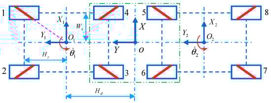
Figure 10.
A tandem configuration composed of two symmetrical four-Mecanum-wheel sub-configurations.
In Figure 10, the coordinate system located in the symmetric center of the tandem configuration is established. Its offset relative to the two local coordinate systems and is . Let be the generalized velocity of the system and the angular velocity of the i-th Mecanum wheel be . The inverse kinematics equations of the two four-Mecanum-wheel configurations are derived when the original coordinate system is moved to the designated coordinate system .
where,
In the above two formulas, the column rank of the Jacobian matrix of the inverse kinematics velocity of a mobile robot is still 2, which verifies that the change of coordinate system will not change the rank, and the two mobile robots still cannot achieve omnidirectional motion alone. If the motion of two mobile robots is considered as a whole, the inverse kinematics equation of the eight-Mecanum-wheel configuration is
According to Formula (48), the inverse kinematics velocity Jacobian matrix of the eight-wheel configuration is a column full rank matrix. The above deduction verifies the correctness of the bottom-roller axle intersection approach and the sub-configuration judgment method. The coordinated motion of the tandem configuration can be realized by controlling the rotational velocities of each wheel of the configuration. This roller axle intersection approach can also be extended to the combination configurations of N four-Mecanum-wheel mobile robots.
5.2. Analysis of Mecanum Wheel Configurations and Combination Configurations for Common Omnidirectional Mobile Robots
Figure 11 shows the Mecanum wheel configurations and their application examples in practical production. Based on the analysis of these configurations, the deduction method of multi-wheel configurations can be synthesized. In Section 4, the optimal configuration of the four-Mecanum-wheel robot has been obtained, which is a symmetrical rectangular configuration, and is denoted as configuration W4. The front-right and rear-left wheels are right-handed wheels, and the four Mecanum wheels are mirror-symmetrical in both the front and rear, and are mirror-symmetrical for the left and right. The KUKA omniMove set with four Mecanum wheels, as shown in Figure 11a, adopts this configuration W4.
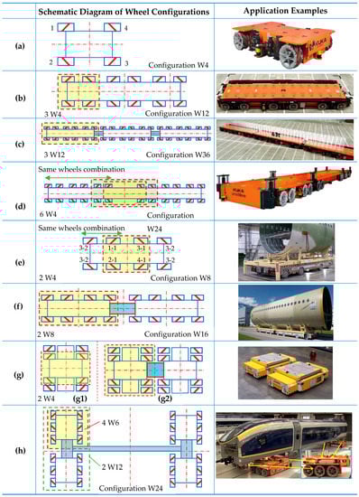
Figure 11.
Common symmetrical rectangular wheel configurations and application examples: (a) the typical four-Mecanum-wheel configuration W4; (b) a 12-Mecanum-wheel configuration W12; (c) a combination configuration W36 with three W12; (d) a 24-Mecanum-wheel configuration W24; (e) an eight-Mecanum-wheel configuration W8, the example: MC-Drive TP 200 of CLAAS; (f) the combination configuration W16 with two W8, the example: the combination of two MC-Drive TP 200 [12]; (g) an eight-Mecanum-wheel configuration W8, which can combine into a 16-Mecanum-wheel configuration [32]; (h) a rectangular combination configuration consisting of four W6 [13]. The examples in (a–d,h) are KUKA omniMove AGVs.
In order to transport large objects, a single mobile robot system needs to use more wheels to improve its carrying and transportation capacity. Figure 11b is a 12-Mecanum-wheel configuration adopted by KUKA’s omniMove platform. This 12-Mecanum-wheel configuration consists of three four-Mecanum-wheel configurations W4, as shown in Figuration 11a, which are connected end and end to form a robot platform. In order to transport objects with larger volume and weight, the 12-Mecanum-wheel configuration robot shown in Figure 11b can be combined to form a 36-Mecanum-wheel combination mobile robot platform. The combined AGVs of the KUKA Omnimove AGV using configuration W36 can carry 63 tons of weight [10]. From Figure 11a–c, we can consider that the configuration W4 shown in Figure 11a is a sub-configuration of the configuration W12 shown in Figure 11b, while the configuration W12 is a sub-configuration of the configuration W36 shown in Figure 11c. Using the sub-configuration judgment method proposed above, both configuration W12 and configuration W36 achieve omnidirectional mobility.
The 24-Mecanum-wheel configuration W24 in Figure 11d is adopted by KUKA, and the eight-Mecanum-wheel configuration W8 shown in Figure 11e is adopted by AGV of CLAAS. Configurations W24 and W8 have the same structural characteristics. The middle four-Mecanum-wheel combination in W8 and W24 can be considered as configuration W4, as shown in Figure 11a. The four wheels on both sides of the middle-four wheels constitute the W4 configuration. The configuration is extended outward from the intermediate configuration W4. Configuration W16 in Figure 11f is a combination of the two configurations of W8 in Figure 11e. The middle configuration W4 and the outer layer configuration W4 are also considered as sub-configurations of the entire Mecanum wheels configuration. The configuration W8 in Figure 11e is a sub-configuration of configuration W16 in Figure 11f. The configurations in Figure 11d and 11e can be considered to be obtained by replacing the Mecanum wheels of the basic configuration W4 with the wheel combination including a row of wheels of the same specification. Mecanum wheels 1, 2, 3, and 4 of configuration W4 in Figure 11a are replaced by wheels 1-1 and 1-2, 2-1 and 2-2, 3-1 and 3-2, 4-1 and 4-2, respectively. Thus, the wheel configuration shown in Figure 11e is evolved. In this way, the configuration W4 is evolved into the wheel configuration W8, which is shown in Figure 11e. In the same way, the configuration W24 in Figure 11d can also be analyzed with the method. The configuration shown in Figure 11g1 can also be obtained by replacing the wheel with the coaxial tandem wheel combination. The combination configuration shown in Figure 11g2 is an end-to-end connection combination of the two configurations in Figure 11g1.
Figure 11h shows a 24-Mecanum-wheel omnidirectional mobile system consisting of four six-Mecanum-wheel configurations W6. The four KUKA omniMove platforms using this configuration W24 are applied to move a railcar body at the Siemens plant. These four mobile robot platforms with configuration W6 are not connected to each other, but each robot platform is connected to the railcar body, thus achieving a fixed connection of the four robot platforms. Two six-Mecanum-wheel configurations W6 are vertically connected to form the 12-Mecanum-wheel subsystem. Two 12-Mecanum-wheel subsystems are connected horizontally to form the 24-Mecanum-wheel configuration W24. The six-Mecanum-wheel configuration W6 consists of a W4 sub-configuration with omnidirectional mobility and a wheelset. Although the configuration W6 is not symmetrical in the longitudinal direction, the configuration W6 is used for combination. The 12-Mecanum-wheel configuration W12 and configuration W24 have symmetrical structures and omnidirectional motion capacity.
5.3. Topological Design Methods of Multi-Mecanum Wheel Configuration for Omnidirectional Mobile Robot
The bottom-roller intersection approach can be used to judge whether the wheel configuration of a single mobile robot system has omnidirectional mobility. The omnidirectional mobility of a multiple-wheel configuration can be judged by the sub-configuration judgment method. Through comprehensive analysis and evaluation, the symmetrical wheel configurations are more conducive to design, manufacture, and motion control. The symmetrical rectangular four-Mecanum-wheel configuration is the optimal wheel configuration in the four-wheel configurations. Based on this basic configuration, the multiple-Mecanum-wheel configuration of an omnidirectional mobile robot can be deduced. In this paper, the topological design methods of the Mecanum-wheel configurations are summarized and refined, including the basic configuration array method, multiple wheel replacement method, and combination method. The first two methods can be used to create suitable multiple-Mecanum-wheel configurations for a single mobile robot based on the basic Mecanum wheel configuration.
Next, the topology methods are introduced in conjunction with Figure 12. The basic configuration array method is obtained based on the sub-configuration judgment method, and it includes a linear array method and a circular array method. The former can be used for new wheel configuration designs base on the symmetrical rectangular wheel configuration, which includes end-to-end connection method and side-by-side connection method. The latter can be used for the design of new wheel configurations based on the centripetal wheel configuration. Using the basic configuration array method, the four-Mecanum-wheel basic configuration is linearly arrayed in two directions; then, the configurations with end-to-end connection and side-by-side connection are obtained, as shown in Figure 12a,b.
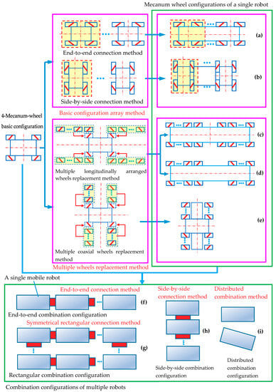
Figure 12.
Topological design methods for wheel configurations based on a symmetrical four-Mecanum-wheel configuration: (a) end-to-end connection configuration; (b) side-by-side connection configuration; (c) a front-back symmetric configuration; (d) a front-back asymmetric configuration; (e) a symmetric configuration with four coaxial wheels series; (f) end-to-end combination configuration; (g) rectangular combination configuration; (h) side-by-side combination configuration; (i) distributed combination configuration.
Using the multiple wheels replacement method, based on the basic four-Mecanum-wheel configuration, each wheel of the four-Mecanum-wheel configuration is replaced with multiple identical wheels. The wheel can be replaced by two types of wheel combinations: a series of longitudinally arranged wheels and a series of coaxial wheels, and the new configurations can be obtained, as shown in Figure 12c–e. If the number of longitudinally arranged wheels in the front- and rear-array wheels is the same, a symmetrical Mecanum-wheel configuration can be obtained, which is symmetrical in both left and right and in front and back, as shown in Figure 12c. If not, the Mecanum wheel configuration is only symmetrical in left and right, and not in front and back, as shown in Figure 12d. Among these configurations, configurations in Figure 12a,c are more commonly used. Using the above two methods, the suitable wheel configurations for the single mobile robot can be obtained. Multiple single robots can be arranged by combination methods, including end-to-end connection, side-by-side connection, symmetrical rectangular connection, and distributed combination methods; and then, the abundant combination configurations of robots can be obtained, including end-to-end combination configuration (Figure 12f), side-by-side combination configuration (Figure 12h), rectangular combination configuration (Figure 12g), and distributed combination configuration (Figure 12i). The distributed combination configuration means that there is no physical connection among the independent mobile robots. This belongs to the research field of multi-robot cooperative motion. In this article, a detailed analysis of the distributed combination configuration is not carried out.
Using the topological design method for Mecanum wheel configurations proposed in this article, abundant wheel configurations can also be deduced based on other basic Mecanum wheel configurations. Using the circular array method, the centripetal three-Mecanum-wheel configuration shown in Figure 7a can be arrayed as a centripetal six-Mecanum-wheel configuration, as shown in Figure 13a1. Using multiple coaxial wheels replacement method, the wheel configuration in Figure 13a2 can be obtained based on configuration in Figure 7a. Using the multiple wheels replacement method, the configurations in Figure 13b1,b2 are obtained from the basic configurations in Figure 8n and the configurations in Figure 13c1 is obtained from the basic configuration in Figure 8o. Using end-to-end combination method, a combination configuration shown in Figure 13c2 can be obtained based on the configuration in Figure 13c1.
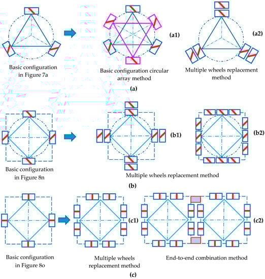
Figure 13.
The examples of deducing new wheel configurations based on three basic Mecanum wheel configurations by using the topological method: (a) new configurations deduced from a centripetal circular array configuration of three Mecanum wheels in Figure 7a; (b) new configurations deduced from centripetal circular array configuration of four Mecanum wheels in Figure 8n; (c) new configurations deduced from centripetal circular array configurations of four orthogonal Mecanum wheels in Figure 8o.
6. Conclusions
The condition that the Mecanum wheeled robot can achieve omnidirectional movement is that the inverse kinematics Jacobian matrix of any three Mecanum wheels on the robot is a column full-rank matrix. In this paper, the relationship between the intersections of bottom-rollers axles of any three Mecanum wheels on the robot and the column rank of the Jacobian matrix is established. A bottom-rollers axles intersections approach for judging the omnidirectional mobility of Mecanum wheel configurations is proposed and proved theoretically, which is a simple and efficient geometric method. If the number of axles intersections is 2 or 3, the column rank is full and the robot can achieve omnidirectional motion in a plane; if the number of axles intersections is 0 or 1, this is not the case.
A sub-configuration judgment method for judging whether a Mecanum wheel configuration has omnidirectional mobility is evolved based on the bottom-roller axle intersections approach. According to this method, if the multiple-Mecanum-wheel configuration has any individual sub-configuration with omnidirectional motion capacity, it can also achieve omnidirectional motion.
The topological design methods of the Mecanum wheel configurations are summarized and refined, including basic configuration array method, multiple wheel replacement method, and combination method. The first two methods can be used to create suitable multiple-Mecanum-wheel configurations for a single mobile robot based on the basic Mecanum wheel configuration. Multiple single robots can be arranged by combination methods including end-to-end connection, side-by-side connection, symmetrical rectangular connection and distributed combination, and then, the abundant combination configurations of robots can be obtained.
Author Contributions
Methodology, Y.L. and S.D.; Validation, L.Z. and Y.S.; Formal analysis, Y.L. and S.D.; Investigation, Y.L. and X.Y.; Writing—original draft preparation, Y.L., S.D., and X.Y.; Writing—review and editing, Y.S. and L.Z.; Project administration, Y.L.
Funding
This work was financially supported by the National Natural Science Foundation of China (no. 51675518), Six Talent Peaks Project in Jiangsu Province (no. JXQC-008), China Scholarship Council (no. 201706425041), Jiangsu Government Scholarship for Overseas Studies (no. JS-2018-152), Science Foundation of Xuzhou University of Technology (no. XKY2018129), and the Priority Academic Program Development of Jiangsu Higher Education Institutions.
Acknowledgments
We would like to thank Robert Bauer of Stevens Institute of Technology for his advice.
Conflicts of Interest
The authors declare no conflict of interest.
References
- Gfrerrer, A. Geometry and kinematics of the Mecanum wheel. Comput. Aided Geom. Des. 2008, 25, 784–791. [Google Scholar] [CrossRef]
- Doroftei, I.; Grosu, V.; Spinu, V. Omnidirectional mobile robot-design and implementation. In Bioinspiration and Robotics: Walking and Climbing Robots; Habib, M.K., Ed.; I-Tech Education and Publishing: Rijeka, Croatia, 2007; pp. 511–528. [Google Scholar]
- Alvito, P.; Marques, C.; Carriço, P.; Freire, J. A Robotic Platform for the Social Robot Project. In Proceedings of the 23rd IEEE International Symposium on Robot and Human Interactive Communication (ROMAN 2014) Workshop on Interactive Robots for Aging and/or Impaired People, Edinburgh, UK, 25–29 August 2014. [Google Scholar]
- Sanbot Max. Available online: http://en.sanbot.com/product/sanbot-max/specification (accessed on 20 May 2019).
- Qian, J.; Zi, B.; Wang, D.; Ma, Y.; Zhang, D. The design and development of an omni-directional mobile robot oriented to an intelligent manufacturing system. Sensors 2017, 17, 2073. [Google Scholar] [CrossRef] [PubMed]
- Sun, S.; Hu, J.; Li, J.; Liu, R.; Shu, M.; Yang, Y. An INS-UWB based collision avoidance system for AGV. Algorithms 2019, 12, 40. [Google Scholar] [CrossRef]
- Adăscăliţei, F.; Doroftei, I. Practical applications for mobile robots based on mecanum wheels-a systematic survey. In Proceedings of the 3rd International Conference on Innovations, Recent Trends and Challenges in Mechatronics, Mechanical Engineering and New High-Tech Products Development(MECAHITECH’11), Bucharest, Romania, 22–23 September 2011; pp. 112–123. [Google Scholar]
- Heß, D.; Künemund, F.; Röhrig, C. Linux based control framework for Mecanum based omnidirectional automated guided vehicles. In Proceedings of the World Congress on Engineering and Computer Science 2013, San Francisco, CA, USA, 23–25 October 2013. [Google Scholar]
- MC Drive Parade. Available online: https://www.youtube.com/watch?v=yf8x2egJRZ4 (accessed on 20 August 2010).
- KUKA omniMove. Available online: https://www.kuka.com/en-us/products/mobility/mobile-platforms/kuka-omnimove (accessed on 20 May 2019).
- Hryniewicz, P.; Gwiazda, A.; Banaś, W.; Sękala, A.; Foit, K. Modelling of a mecanum wheel taking into account the geometry of road rollers. In Proceedings of the IOP Conference Series: Materials Science and Engineering, Sibiu, Romania, 14–17 June 2017; p. 012060. [Google Scholar]
- Airbus Rolls Out Its Second A350 XWB Composite Fuselage Demonstrator. Available online: https://www.airbus.com/newsroom/news/en/2009/08/airbus-rolls-out-its-second-a350-xwb-composite-fuselage-demonstrator.html (accessed on 7 August 2009).
- Automation, K.-R. KUKA omniMove at Siemens Plant Krefeld. Available online: https://www.youtube.com/watch?v=EvOrFgSmQoc (accessed on 2 October 2014).
- He, C.; Wu, D.; Chen, K.; Liu, F.; Fan, N. Analysis of the Mecanum wheel arrangement of an omnidirectional vehicle. Proc. Inst. Mech. Eng. Part C J. Mech. Eng. Sci. 2019, 233, 5329–5340. [Google Scholar] [CrossRef]
- Muir, P.F.; Neuman, C.P. Kinematic modeling of wheeled mobile robots. J. Robot. Syst. 1987, 4, 281–340. [Google Scholar] [CrossRef]
- Muir, P.F. Modeling and Control of Wheeled Mobile Robots; Carnegie Mellon University: Pittsburgh, PA, USA, 1988. [Google Scholar]
- Angeles, J. Fundamentals of Robotic Mechanical Systems: Theory, Methods, and Algorithms, 4th ed.; Springer: Cham, Switzerland, 2002. [Google Scholar] [CrossRef]
- Campion, G.; Bastin, G.; D’Andrea-Novel, B. Structural properties and classification of kinematic and dynamic models of wheeled mobile robots. In Proceedings of the 1993 IEEE International Conference on Robotics and Automation, Atlanta, GA, USA, 2–6 May 1993; pp. 462–469. [Google Scholar]
- Gracia, L.; Tornero, J. A new geometric approach to characterize the singularity of wheeled mobile robots. Robotica 2007, 25, 627–638. [Google Scholar] [CrossRef]
- Gracia, L.; Tornero, J. Kinematic modeling of wheeled mobile robots with slip. Adv. Robot. 2007, 21, 1253–1279. [Google Scholar] [CrossRef]
- Zhang, Y.; Wang, S.; Zhang, J.; Su, Q.; Gao, J. Research on motion characteristic of omnidirectional robot based on mecanum wheel. In Proceedings of the 2010 International Conference on Digital Manufacturing & Automation, Washington, DC, USA, 18–20 December 2010; pp. 237–241. [Google Scholar]
- Wang, S.; Zhang, Y.; Nie, B.; Xia, Y. Research on steering motion of omnidirectional platform based on Mecanum wheel. In Proceedings of the 2011 Second International Conference on Mechanic Automation and Control Engineering, Inner Mongolia, China, 15–17 July 2011; pp. 5177–5180. [Google Scholar]
- Wang, Y.; Chang, D. Motion Performance Analysis and Layout Selection for Motion System with Four Mecanum Wheels. J. Mech. Eng. 2009, 45, 307–310, 316. [Google Scholar] [CrossRef]
- Wang, Y.; Chang, D. Motion restricted condition and singular configuration for mecanum wheeled omni-directional motion system. J. Shanghai Univ. (Natl. Sci.) 2009, 15, 181–185. [Google Scholar]
- Mishra, S.; Sharma, M.; Mohan, S. Behavioural Fault tolerant control of an Omni directional Mobile Robot with Four mecanum Wheels. Def. Sci. J. 2019, 69, 353–360. [Google Scholar] [CrossRef]
- Gao, P.; Peng, J.; Yu, W.; Li, S.; Qin, X. Design and Motion Analysis of a Mecanum Three-Round Omni-Directional Mobile Platform. J. Northwest. Polytech. Univ. 2017, 35, 857–862. [Google Scholar]
- Zhang, Y.N.; Wang, S.S.; Zhang, J.; Song, J. Research on motion characteristic of omnidirectional device based on Mecanum wheel. In Proceedings of the 2011 International Conference on Electric Information and Control Engineering, Wuhan, China, 15–17 April 2011; pp. 6094–6097. [Google Scholar]
- Indiveri, G. Swedish wheeled omnidirectional mobile robots: Kinematics analysis and control. IEEE Trans. Robot. 2009, 25, 164–171. [Google Scholar] [CrossRef]
- Wang, C.; Liu, X.; Yang, X.; Hu, F.; Jiang, A.; Yang, C. Trajectory tracking of an omni-directional wheeled mobile robot using a model predictive control strategy. Appl. Sci. 2018, 8, 231. [Google Scholar] [CrossRef]
- Li, J.; Zhang, L. The Teleoperation System of Service Robot Based on Cloud Services. J. Comput. 2017, 28, 231–245. [Google Scholar]
- Li, Y.W.; Dai, S.M.; Shi, Y.; Zhao, L.L.; Ding, M.H. Navigation simulation of a Mecanum wheel mobile robot based on an improved A* algorithm in Unity3D. Sensors 2019, 19, 2976. [Google Scholar] [CrossRef] [PubMed]
- 44 MC DRIVE TP200 700 TDE. Available online: https://www.youtube.com/watch?v=iir0CINszQo (accessed on 24 October 2010).


© 2019 by the authors. Licensee MDPI, Basel, Switzerland. This article is an open access article distributed under the terms and conditions of the Creative Commons Attribution (CC BY) license (http://creativecommons.org/licenses/by/4.0/).