Article

Structural Monitoring and Performance Assessment of Shield Tunnels during the Operation Period, Based on Distributed Optical-Fiber Sensors

1
School of Earth Science and Engineering, Nanjing University, Nanjing 210093, China
2
China Design Group Corporation Limited, Nanjing 210014, China
Symmetry 2019, 11(7), 940; https://doi.org/10.3390/sym11070940
Submission received: 21 June 2019 / Revised: 11 July 2019 / Accepted: 17 July 2019 / Published: 19 July 2019

Abstract

:
The weak parts of shield tunnels are not obvious, so it is urgently necessary to implement distributed monitoring based on an advanced sensing method. As the horizontal loads at both sides of the shield tunnel present a type of symmetric distribution, the deformation parameters under the vertical loads are often selected as the key monitored parameters, such as convergence, settlement, and seam opening. In this paper, the monitoring of the proposed deformation parameters is innovatively implemented with only one sensing technology, namely distributed optical-fiber strain sensing technology. First, the improved distributed optical-fiber sensors are introduced with the sensing performance. Second, a structural health monitoring (SHM) system for operational shield tunnels is proposed, including optical-fiber sensor installation, data logging and saving, key parameter analysis, and structural health assessment. The key monitoring theory and technology are also proposed. The proposed system has been verified by experiments at the Nanjing Yangtze River tunnel. In the experiments, the proposed optical-fiber sensors were installed on the surface of a selected tunnel ring, with a longitudinal span of approximately 90 m long. The experiments were conducted over 55 days to measure the distributed strain and temperature. Then the key parameters were obtained from the measurements, with which the structural health was assessed. The possibility that the shield tunnel SHM system can be constructed with the improved distributed optical-fiber sensors, monitoring theory, and technology is proven.

1. Introduction

Recently, large-scale infrastructure is being constructed in many cities, such as subways and pathways that cross rivers or seas. Due to their small effect on the environment, shield tunnels have been widely applied. However, there are obvious characteristics, such as being a large investment, being underground, a complicated service environment, and so on, that cause the safety of these tunnels to greatly affect people’s lives and social economy. Therefore, a key issue is to intelligently monitor the structural safety state of shield tunnels during the operation period.
In the field of civil engineering, researchers have already proposed the concept of structural health monitoring (SHM) of bridges and buildings, and have made significant actual progress in theory and application [1,2,3,4,5]. However, it is not easy to apply the methods from bridge or building SHM to shield tunnels, since there are obvious differences between the two types of structures. Therefore, researchers have conducted studies on tunnels [6,7,8,9], but most studies on tunnel SHM only focused on key cross sections of those tunnels. In fact, the weak segments of a shield tunnel structure are not significant; every section may be weak segment. Therefore, it is difficult to construct a tunnel SHM system based on the traditional sensing technology, as used for the bridge.
Distributed sensing techniques [10,11,12], such as the Brillouin optical time-domain reflectometer (BOTDR) and Brillouin optical time-domain analysis (BOTDA), have great potential for tunnel SHM. The sensors can cover the whole structure length with low cost and good sensitivity. For example, Zhishen Wu et al. bonded fiber optic sensors with BOTDR on the surface of a poly-p-phenylene benzobisoxazole (PBO) fiber reinforced polymer (FRP) sheet to retrofit a concrete beam [13]. During the static load tests, these authors successfully obtained a continuous strain distribution along the whole beam. Filippo Bastianini et al. also obtained the strain distribution of a concrete bridge under static load with BOTDR [14]. Due to its great sensing advantages, some researchers have also applied BOTDR to tunnel monitoring. Yong Ding et al. discussed the feasibility of constructing a tunnel SHM system based on distributed optical-fiber sensors [15]. Most studies were implemented with sensors embedded in the structure, but for the existing shield tunnels, the sensors cannot be embedded inside them to monitor the internal structural forces.
In this paper, the research was implemented based on distributed optical-fiber sensing technology. A new sensor was proposed to monitor the shield tunnel displacement; then, the displacement was applied to identify the level of tunnel health status. The SHM system was proposed for shield tunnels during the operation period, and verified by field tests of the Nanjing Yangtze river tunnel.

2. Distributed Optical-Fiber Sensor

2.1. New Packaged Optical-Fiber Sensors

The common optical-fiber (OF) sensor cannot be used to monitor structures because it breaks too easily, so a special package must be applied. In this paper, a new type of sensor package is introduced, as shown in Figure 1. In Figure 1, an additional plastic tube is added in the middle part of the sensor, which prevents the middle part of the optical-fiber sensor from bonding with the Basalt fiber, while the optical-fiber sensor is bonded at the two ends. This setup is designed to monitor the seam or a large crack especially, since the deformation will not easily break the sensor.

2.2. Sensing Performance of the Proposed Sensor

The Brillouin frequency shift νB of the optical-fiber sensor changes in proportion to the change in strain or temperature along the optical fiber. The linear relationships between the Brillouin frequency shift and the strain or temperature are given as follows:
ν B ( T 0 , ε ) = C ε ( ε ε 0 ) + ν B 0 ( T 0 , ε 0 ) ,
ν B ( T , ε 0 ) = C T ( T T 0 ) + ν B 0 ( T 0 , ε 0 ) .
In the formula, ε is the strain, with the unit of µε; T is the temperature, with the unit of °C; ν B is the Brillouin frequency, with the unit of MHz; T 0 and ε 0 are the temperature and strain, respectively, which correspond to a reference Brillouin frequency ν B 0 ; C ε is the strain coefficient, with the unit of MHz/µε; and C T is the temperature coefficient, with the unit of MHz/°C.
The strain and temperature sensing performance were verified by static extension and temperature tests, where the long-gauge-type sensor was applied. The results are shown in Figure 2, which confirm the linear relationships between Brillouin shift and strain, as well as between Brillouin shift and temperature. The sensing repeatability is also found in different specimens. The strain coefficient is 50.5 MHz/0.1%, and the temperature coefficient is 1.13 MHz/°C, which are very close to the theoretical values (49.7 MHz/0.1% and 1.07 MHz/°C), and also verify the good sensing performance of the proposed sensor.

3. Structural Monitoring and Performance Assessment System of Shield Tunnels

3.1. Framework of the Structural Health Monitoring System of Shield Tunnels

Based on the proposed distributed optical-fiber sensing technology, the tunnel SHM system can be constructed as shown in Figure 3. The system includes four main parts: parameter selection and OF sensor installation, data collection/storage, key parameter analysis, and performance assessment.
(1) Parameters selection and OF sensor installation:
The deformations of shield tunnels during the operation period include circumferential convergence, vertical settlement, seam opening, horizontal torsion, and horizontal displacement. Because the horizontal loads at both sides of a shield tunnel present a type of symmetric distribution in most cases, the horizontal torsion and horizontal displacement are often small, so they in fact can be ignored. However, the deformations under the vertical loads are often selected as the key monitored parameters, such as seam opening, convergence, and settlement.
To implement the monitoring of the proposed deformation parameters, first, the location where the sensors are installed must be selected. Considering the long-range coverage ability, the tunnel can be covered by sensors along the entire length. However, some optimized line should be selected, because it is not necessary to install sensors all over the tunnel. For the cross section, key lines should also be found based on the tunnel environment, existing structure damage, etc. In addition, sensor parameters, such as the gauge length and sensor length for temperature sensing, should be selected. In addition to the necessary sensors, additional sensors should be installed, in order to guarantee the normal operation of the sensing system if some sensors are broken. The sensors should also be repairable.
(2) Data collection/storage:
The data collected by the optical fiber should be related to the detailed structure location. The strain data can be processed with the temperature compensation.
(3) Key parameter analysis:
Based on the measured strain distribution, the changes in seam width, convergence, settlement, and other key displacement parameters can be analyzed. Simultaneously, the inner force of the key structure parts can be analyzed, based on the displacement.
(4) Performance assessment:
There are two levels for performance assessment: Level I and Level II. In Level I, some parameter thresholds are set, in order to decide whether the monitored tunnel is normal or abnormal. If some obvious abnormal cases occur, further assessment should be implemented, i.e., Level II assessment. In Level II, the monitored structural parameters are input into the finite element (FE) model of the monitored tunnel to calculate the structural inner force, which can be used to implement the comprehensive performance assessment.

3.2. Key Theory and Technology for Structural Monitoring and Performance Assessment

3.2.1. Seam Width Monitoring

The number of shield tunnel seams is too large, and it is not easy to monitor the change in seam width. As shown in Figure 4, the sensing method of a long gauge is applied to monitor the seam width, which can be expressed as follows:
W = ε ¯ * L .
In the formula, W is the change in seam width, ε ¯ is the average strain along the sensing gauge length, and L is the sensing gauge length.

3.2.2. Convergence and Settlement Monitoring

Based on mechanic knowledge, there is a good relationship between strain and displacement, as shown in Equation (4):
D = ε M y M ¯ d x + ε N N ¯ d x + ε Q Q ¯ d x
In the formula, D is the total convergence of the shield tunnel; ε M , ε N , and ε Q are the bending strain, axial strain, and shear strain, respectively; M ¯ , N ¯ , and Q ¯ are the virtual bending moment, virtual axial force, and virtual shear force, respectively.
In addition to the displacement calculated from Equation (4), the displacement caused by the rotation at the seam should also be considered. The tunnel cross section model is shown in Figure 5, where the spring hinge stands for the seam. In Equation (4), the displacements caused by the axial strain and shear strain are small, so they can be ignored in this paper.
Therefore, the first part of the convergence is expressed as follows:
D 1 = ε M y M ¯ d x .
To calculate another part, the change in seam width should first be calculated as shown in Equation (3), the model of which is shown in Figure 6. Then, the change in rotation α can be calculated as follows:
α = W / 2 y L = ε ¯ L 2 y L .
In the formula, y L is the distance from the sensor to the neutral axis. Finally, the second part of the convergence is expressed as follows:
D 2 = l * ( cos α cos ( α + α ) ) l * α * sin ( α + α 2 ) .
In the formula, α is the initial angle and l is the chord length of a segment, as shown in Figure 6. The chord length l remains unchanged in the calculation.
Then, the convergence of the shield tunnel can be calculated as follows:
D = D 1 + D 2 = ξ M y M ¯ d x + l α sin ( α + α 2 ) .
For the longitudinal direction, the shield tunnel is often simplified as a continuous beam, as shown in Figure 7. Therefore, the settlement can be calculated by Equation (4). However, the axial strain and shear strain slightly affect the settlement, so Equation (5) is also applied, in order to calculate the settlement in this paper.

3.2.3. Structural Performance Assessment Method

The process of the structural performance assessment method in this paper is as follows: first, the FE model of the tunnel is modified based on the inspection results; second, the monitored displacement is input into the model to calculate the inner force; and finally, the assessment is implemented based on the code or criterion.

4. Field Experiments at the Nanjing Yangtze River Tunnel

4.1. Experiment Description

The Nanjing Yangtze River tunnel is an important pathway along the Yangtze River in China. There are obvious characteristics of the shield tunnel, such as a large diameter of 14.93 m, a high water pressure of 650 kPa, a thin coverage soil of approximately 10 m under the groove area, and a complicated geology. Therefore, it is important to apply tunnel SHM to maintain the structure’s safety. The middle part of the tunnel, which is buried in deep soil with the highest water pressure, was selected as the experimental area. One cross section and a 90 m-long longitudinal section were selected to install sensors. The experiments aimed to verify the feasibility of using the proposed OF sensor to build an operational shield tunnel SHM system.

4.2. Sensor Installation

In the experiments, the OF sensors were packaged with basalt fiber, as shown in Figure 8, which increases the sensor durability and strength to survive the installation process. In Figure 9, the sensors covered 78% of the cross section of the tunnel, whereas the remaining 21% of the tunnel cross section had no space to install sensors. In the calculation, the strain for the 21% is generated by interpolation. OF sensors with a 30 cm gauge length were installed at the seam of the cross section. Meanwhile, all bonded sensors were applied to monitor the concrete strain. The sensors along the longitudinal direction were installed similar to those for the cross section, but additional sensors were placed for temperature sensing with a space of 20 m.
After the sensor installation, the OF sensor should be located so that the measured data relates to the actual structure’s location. A typical initial strain distribution is presented in Figure 10, which shows that there are several sharp strain peaks. These sharp strain peaks are located at the segment seams, and the sensors are extended to present some initial strain for implementing the measurement if the seam width decreases. The figure also shows that the initial strain is smaller for the temperature-monitoring sensors, which can be used to locate the sensors.

4.3. Monitoring Results of Some Key Parameters

The system ran for 55 days, and one measurement was implemented each hour. Thus, key structure parameters can be assessed according to the strain and temperature test data.

4.3.1. Strain

The typical strain test results of the cross section and longitudinal direction are shown in Figure 11, and they have been compensated by the temperature effect. The strain data obtained at the first measurement are taken as a basis. The strain test results for other measurements represent the change based on the first strain measurement. From the typical results in Figure 11, the strain fluctuates with a range of −50 to +50 με, most of which is due to the strain measurement error of the measurement machine, as the Brillouin sensing accuracy is approximately 10 με. Therefore, during the monitoring time, the shield tunnel structure showed a very small deformation.

4.3.2. Seam Width

The seam width change can be calculated with Equation (3). The typical results are shown in Figure 12. The seam width changes more in the longitudinal direction than in the cross section. The maximum variations of the longitudinal and circular seam widths are 0.21 and 0.15 mm, respectively.

4.3.3. Convergence

The convergence can be calculated with Equation (8). The typical results are shown in Figure 13. From the results, the convergence deformation at the arch foot of the shield tunnel is maximal. The largest monitored convergence is only 0.3 mm, which is also not larger than the limit.

4.3.4. Settlement

The settlement for the longitudinal direction is calculated as shown in Figure 14. At the two ends of the monitored zone, the vertical displacement is set as zero. In the figure, the positive value indicates that the displacement occurs downward, and the negative value indicates that the displacement occurs upward. The results show that the largest settlement is approximately 0.12 mm, which does not reach the value to trigger an alarm. The settlement is very small, which indicates that the tunnel is very stable. The settlement results in Figure 14 show that the settlement on the 30th day was the highest, because the water level of the Yangtze River had risen by 2~2.5 m during this period.

4.4. Structural Performance Assessment

The thresholds of the key parameters were calculated according to the design scheme. Through these thresholds, the level of structural health of the Nanjing Yangtze River shield tunnel can be divided into four levels, as shown in Table 1. In level 1, the upper limit is that the structural health affects the normal operation of the tunnel, where water leakage occurs; in level 2, the upper limit is the limit state of normal service of the structures, where concrete cracking occurs; in level 3, the upper limit is 80% of the designed bearing capacity; and in level 4, the upper limit is the designed bearing capacity.
According to Table 1, the test section of the Nanjing Yangtze River shield tunnel was assessed as level 1, meaning that there is no obvious damage, and no need to implement the assessment of level 2.
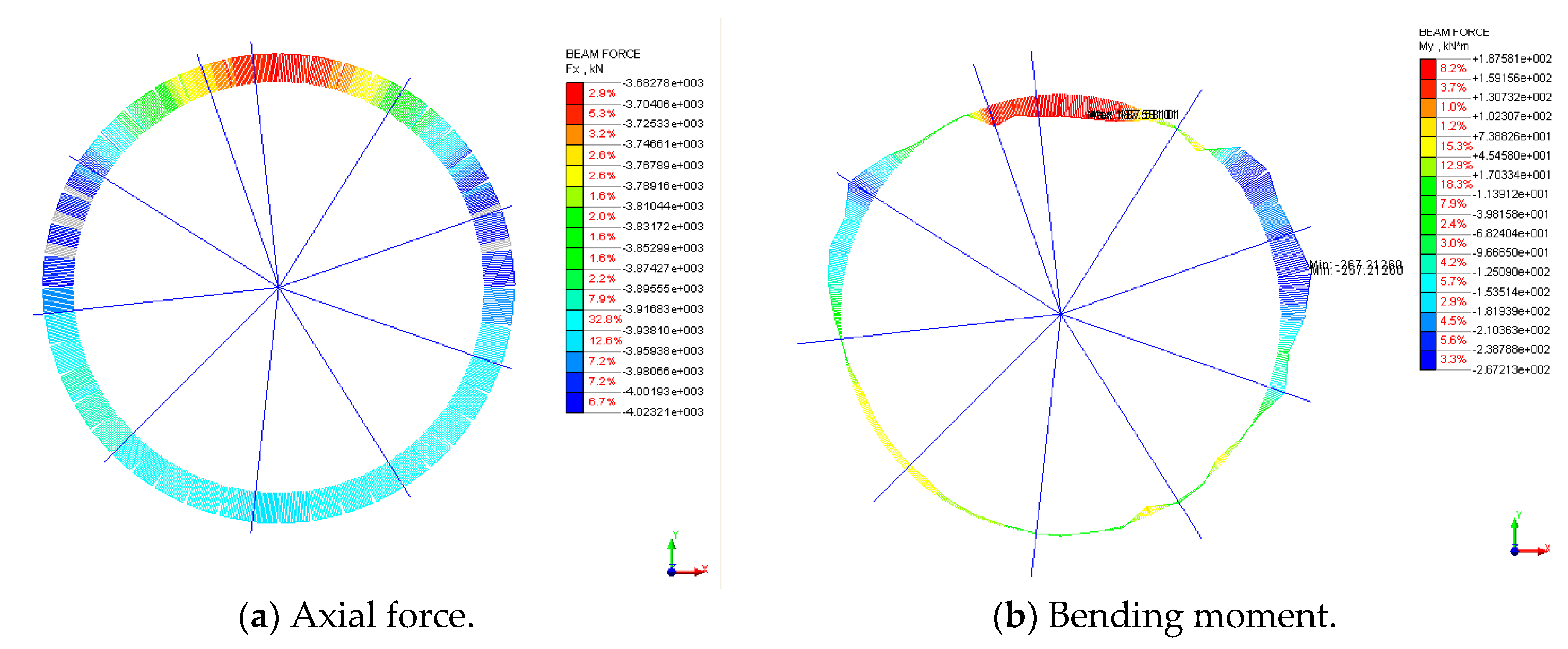
The above table can only be used to evaluate the safety status of the Nanjing Yangtze River shield tunnel. To more accurately determine the safety of the tunnel, the finite element (FE) model should be established, with the monitored displacement input into the model to calculate the inner force of the tunnel. The geometric shape of the shield tunnel is symmetrical, so the shield segment structure can be simplified to a homogeneous ring model. The load-structure method is used in finite element calculation with the FEM software MIDAS/GTS, in which the soil around the tunnel is equivalent to the load and pressure-only spring, and the structure of the shield tunnel is equivalent to the beam element. The test section was under the Yangtze River, with a water depth of up to 30 m and a covered soil thickness of 19.17 m. The computational section sketch is shown in Figure 15. The convergence obtained from the test is input into the FE model as a type of load, as shown in Figure 16. The FE simulation results are shown in Figure 17. According to the results, the largest axial force was 4023.2 kN, and the largest bending moment was 267.2 kN·m. According to the design parameters and mechanical calculation, the structure of the test section is still in the elastic status.

5. Conclusions

In this paper, distributed optical-fiber sensing technology is applied to solve the problem of tunnel SHM. From our research, the following conclusions are drawn:
(1) The distributed optical-fiber sensing technology is a key technology to build a tunnel SHM system, due to its sensing advantages in strain and temperature sensing.
(2) The tunnel SHM system can be constructed with distributed optical-fiber sensing technology, which mainly includes four parts: parameter selection and OF sensor installation, data collection/storage, key parameter analysis, and performance assessment.
(3) With the distributed optical-fiber sensing technology, key parameters, such as the seam width, convergence, and settlement, can be monitored for a shield tunnel.
(4) Based on the field experiments at the Nanjing Yangtze River shield tunnel, the proposed tunnel SHM system is verified.
From the research in this paper, the proposed method has good potential. However, much work must be performed for implementation, especially considering the long-term monitoring requirements, such as durability and stability.

Author Contributions

T.W. took the problem and wrote the manuscript. B.S. proposed the new type of distributed, long-gauge optical-fiber sensors, and revised the manuscript. Y.Z. implemented the field experiments and discussed the results. All authors finalized the manuscript after its internal evaluation.

Funding

The authors are grateful for the financial support provided by the State Key Program of National Natural Science of China (Grant Nos. 41427801, 41230636), Public Science and Technology Research Fund of Ministry of Land and Resources (Grant No. 201511055), and Geological Survey of Jiangsu Province (Grant No. 201401).

Conflicts of Interest

The authors declare no potential conflicts of interest with respect to the research, authorship, and publication of this article.

References

  1. Cardini, A.J.; Dewolf, J.T. Long-term structural health monitoring of a multi-girder steel composite bridge using strain data. Struct. Health Monit. 2008, 8, 47–58. [Google Scholar] [CrossRef]
  2. Ubertini, F.; Comanducci, G.; Cavalagli, N. Vibration-based structural health monitoring of a historic bell-tower using output-only measurements and multivariate statistical analysis. Struct. Health Monit. 2016, 15, 438–457. [Google Scholar] [CrossRef]
  3. Huynh, T.C.; Lee, S.Y.; Dang, N.L.; Kim, J.T. Vibration-based structural identification of caisson-foundation system via in-situ measurement and simplified model. Struct. Control. Health Monit. 2019, 26, e2315. [Google Scholar] [CrossRef]
  4. Kim, J.T.; Park, J.H.; Huynh, T.C.; Lee, K.S. Wind and traffic-induced variation of dynamic characteristics of a cable-stayed bridge-benchmark study. Smart Struct. Syst. 2016, 17, 491–522. [Google Scholar]
  5. Wan, C.; Zhao, L.; Ding, Y.; Xue, S. A two-phase ranging algorithm for sensor localization in structural health monitoring. Adv. Mech. Eng. 2016, 9, 1–8. [Google Scholar] [CrossRef]
  6. Su, J.; Zhang, D.; Niu, X.; Fang, Q. Research on design of subsea tunnel structural health monitoring. Chin. J. Rock Mech. Eng. 2007, 26, 3785–3792. [Google Scholar]
  7. Zhou, B.; Xie, X.Y.; Li, Y.S. A structural health assessment method for shield tunnels based on torsional wave speed. Sci. China Technol. Sci. 2014, 57, 1109–1120. [Google Scholar] [CrossRef]
  8. Liu, S.C.; Zhang, D.; Huang, J.; Zhang, C. Research and design on structural health monitoring system for large-scale shield tunnel. Chin. J. Undergr. Space Eng. 2011, 7, 741–748. [Google Scholar]
  9. Wang, B.; He, C.; Wu, D.X. Ideas of tunnel structure health monitoring system and its technology. J. Railw. Eng. Soc. 2012, 160, 67–72. [Google Scholar]
  10. Sakairi, Y.; Uchiyama, H.; Li, Z.X.; Adachi, S. A system for measuring temperature and strain separately by BOTDR and OTDR. In Advanced Sensor Systems and Applications, Proceedings of SPIE-The International Society for Optical Engineering, Shanghai, China, 9 September 2002; SPIE: Bellingham, WA, USA, 2002; Volume 4920, pp. 33–38. [Google Scholar]
  11. Kishida, K.; Li, C.H. Pulse pre-pump-BOTDA technology for new generation of distributed strain measuring system. Struct. Health Monit. Intell. Infrastruct. 2006, 471–477. [Google Scholar]
  12. Wei, H.; Zhao, X.; Kong, X.; Zhang, P.; Cui, Y.; Sun, C. The Performance Analysis of Distributed Brillouin Corrosion Sensors for Steel Reinforced Concrete Structures. Sensors 2014, 14, 431–442. [Google Scholar] [CrossRef] [PubMed]
  13. Wu, Z.; Xu, B.; Hayashi, K.; Machida, A. Distributed fibre optic sensing for a full-scale PC girder strengthened with prestressed PBO sheets. Eng. Struct. 2006, 28, 1049–1059. [Google Scholar] [CrossRef]
  14. Bastianini, F.; Rizzo, A.; Galati, N.; Deza, U.; Nanni, A. Discontinuous Brillouin strain monitoring of small concrete bridges:comparison between near-to-surface and “smart” FRP fibre installation techniques. In Smart Structures and Materials 2005: Sensors and Smart Structures Technologies for Civil, Mechanical, and Aerospace Systems, Proceedings of SPIE Smart Structures and Materials + Nondestructive Evaluation and Health Monitoring, San Diego, CA, USA, 17 May 2005; SPIE: Bellingham, WA, USA, 2005; Volume 5765, pp. 612–623. [Google Scholar]
  15. Ding, Y.; Shi, B.; Sui, H. Tunnel structural health monitoring system and fiber optic sensing technology. J. Disaster Prev. Mitig. Eng. 2005, 25, 375–380. [Google Scholar]
Figure 1. Distributed long-gauge optical-fiber sensor.
Symmetry 11 00940 g001
Figure 2. Sensing performance of the new packaged optical-fiber sensor.
Symmetry 11 00940 g002
Figure 3. Framework of the structural monitoring and performance assessment system of shield tunnels.
Symmetry 11 00940 g003
Figure 4. Sensor installation at the seam.
Symmetry 11 00940 g004
Figure 5. Convergence calculation model.
Symmetry 11 00940 g005
Figure 6. Calculation model.
Symmetry 11 00940 g006
Figure 7. Settlement calculation model.
Symmetry 11 00940 g007
Figure 8. Packaged optical-fiber (OF) sensor.
Symmetry 11 00940 g008
Figure 9. Installation of the OF sensors.
Symmetry 11 00940 g009aSymmetry 11 00940 g009b
Figure 10. Typical initial strain distribution of the optical-fiber sensors.
Symmetry 11 00940 g010
Figure 11. Typical strain monitoring results.
Symmetry 11 00940 g011
Figure 12. Typical results of seam width monitoring.
Symmetry 11 00940 g012
Figure 13. Typical results of convergence monitoring.
Symmetry 11 00940 g013
Figure 14. Typical results of settlement monitoring.
Symmetry 11 00940 g014
Figure 15. Computational section sketch (unit: kPa).
Symmetry 11 00940 g015
Figure 16. Convergence imposed on a tunnel as loads.
Symmetry 11 00940 g016
Figure 17. Results of the finite element (FE) simulation.
Symmetry 11 00940 g017
Table 1. Level of structural health assessment of the Nanjing Yangtze River shield tunnel.
Health Level1234
Settlement (mm/10 m)s < 44 < s ≤ 1010 < s ≤ 50s > 50
Seam width (mm)W < 66 < W ≤ 1010 < W ≤ 30W > 30
Convergence (mm)D ≤ 5050 < D ≤ 8080 < D ≤ 200D > 200