Article

Asymmetric Scattering and Reciprocity in a Plasmonic Dimer

1
Independent Researcher, Baran Sitesi F-6, Ordu 52200, Turkey
2
Department Física Aplicada, Universitat de Barcelona, 08028 Barcelona, Spain
3
Institute of Nanoscience and Nanotechnology (IN2UB), Universitat de Barcelona, 08028 Barcelona, Spain
*
Author to whom correspondence should be addressed.
Symmetry 2020, 12(11), 1790; https://doi.org/10.3390/sym12111790
Submission received: 8 October 2020 / Revised: 20 October 2020 / Accepted: 22 October 2020 / Published: 29 October 2020
(This article belongs to the Special Issue Symmetry in Nonlinear Optics)

Abstract

:
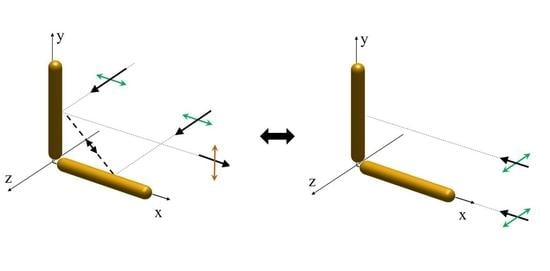
We study the scattering of polarized light by two equal corner stacked Au nanorods that exhibit strong electromagnetic coupling. In the far field, this plasmonic dimer manifests very prominent asymmetric scattering in the transverse direction. Calculations based on a system of two coupled oscillators, as well as simulations based on the boundary element method, show that, while in one configuration both vertical and horizontal polarization states are scattered to the detector, when we interchange the source and the detector, the scattered intensity of the horizontal polarization drops to zero. Following Perrin’s criterion, it can be shown that this system, as well as any other linear system not involving magneto-optical effects, obeys the optical reciprocity principle. We show that the optical response of the plasmonic dimer, while preserving electromagnetic reciprocity, can be used for the non-reciprocal transfer of signals at a subwavelength scale.

Graphical Abstract

1. Introduction

One of the future directions of nano-photonics is creating on-chip large-scale integrated optical systems. In this context, considerable effort is dedicated to the study of directional nanodevices which can exhibit nonreciprocal propagation of electromagnetic waves at a subwavelength scale. In optical experiments one must distinguish reciprocity from time-reversal symmetry as dissipation violates strict time-reversal symmetry of an experiment; however, it can be still reciprocal [1]. Generally, an optical system is considered to be reciprocal if one can switch source and detector and get the same result. This definition (usually termed as Helmholtz reciprocity) is very useful in optical experiments because it is applicable even if in the presence of absorption or scattering processes that lack “true” time-reversal symmetry. However, in the context of electromagnetism, the understanding of reciprocity (here usually called Lorentz reciprocity) is more strict, so that the concept of non-reciprocity of the wave propagation is almost exclusively associated to magneto-optic media [2]. These magnetic materials have wide applications in microwave and optical technologies that allow for the fabrication of optical isolators and circulators. According to this electromagnetic formulation, devices that are non-reciprocal in their properties are this way because of the asymmetry of the permittivity and/or permeability tensors ( ε ε T , μ μ T ) of magneto-optical media they contain.
Many linear optical processes that do not involve magneto-optical media may still have a non-reciprocal optical response, meaning that switching sources and detector effectively changes the experiment. This was first considered by Perrin [3] and later generalized by Van de Hulst [4] when considering scattering in an optical medium. As it noted by Barron [5], this happens because light scattering is not a reversible phenomenon, so that reversing only the scattering beam in the direction of interest, but ignoring the beams scattered into all other directions, does not restore the incident beam to its original condition. Later we will come back to this point, but it is important to remark from the beginning that this type of optical non-reciprocity, also observed in absorbing nanomaterials [6,7], is not equivalent to the non-reciprocity of systems based on magneto-optical effects, because they do not involve any violation of Lorentz reciprocity.
This paper is devoted to the study of scattering of polarized light by a plasmonic dimer made by two equal corner stacked nanorods. A nanorod dimer is an archetypal optical nanoantenna and it is usually considered as a model system in plasmonics [8,9,10,11,12]. Although antennas are key elements for many devices at radiowave or microwave regimes, their optical analog is not yet fully prominent in current optical technology. Instead, optical radiation is mostly manipulated by redirecting the wavefronts with lenses and mirrors. Such manipulation relies on the wave nature of the electromagnetic waves but, because of the diffraction limit, it is not suitable to control the field at the subwavelength scale. In this work, we consider only systems with linear responses where matrix representations of fields and transfer operators naturally arise, which we will express with the Jones formalism. The Jones formalism will be particularly useful as Van de Hulst [4] showed how a 2 × 2 scattering matrix or Jones matrix ( J ) transforms under a reciprocal transformation:
j 00 j 01 j 10 j 11 j 00 j 10 j 01 j 11 .
Due to their aspect ratio and their localized surface plasmon response, metallic nanorods are highly sensitive to the polarization orientation of light. Moreover, when the gap distance between the antennas is small enough, the dipole modes of the individual nanorods will couple, hybridizing in bonding and antibonding modes, respectively, at higher and lower energies [13]. We show, through analytic calculations, that a very prominent non-reciprocal response appears when one considers 90 scattering in the dimer. The electromagnetic response that we obtain in terms of the scattering matrix also confirms the numerical simulations based on the boundary element method using realistic gold plasmonic nanoparticles. In this work, we derive an analytical solution for the transverse scattering of the plasmonic dimer to study its non-reciprocal optical response which, ultimately, can be used to produce nonreciprocal directional light sources or detectors, which is one of the desired features for certain solid-state nanoatennas in optics communications [14]. We show that this can be achieved, while still preserving electromagnetic reciprocity, if one attends to the different polarization channels.

2. Scattering in the Plasmonic Dimer

We consider a plamonic dimer formed by two equal gold nanorods arranged in a corner stacked position, as they are shown in Figure 1. Right angle scattering (90 scattering angle) will be studied in two different configurations, that we identify as Case A and Case B, one being the reciprocal of the other. As shown in Figure 1, the source (S) position of Case A corresponds to the detector (D) position of Case B and vice-versa.

2.1. Simulations

The electromagnetic response of the plasmonic antenna-like particles is calculated using the boundary element method (BEM). We used the MATLAB implementation of the BEM method developed by Hohenester et al. (MNPBEM toolbox) [15]. In all the simulations reported in our work, the gold nanorod is considered to be 400 nm in length and 50 nm in diameter. A small gap of 5 nm between the ends of the rods is considered. The optical constants of Au are taken from Johnson and Christy [16] with the data extrapolated to the infrared range by the Drude model [17]. The configurations in cases A and B are compared by calculating the far field scattered intensities for horizontal and vertical polarization states. The simulation results include the wavelength region from 1000 nm to 2000 nm, that correspond to the main electric dipole resonance of the rods.
We include as Supplementary Material the MATLAB files necessary to reproduce the simulations reported in this work using the MNPBEM toolbox.

2.2. Calculations

A metallic nanorod can be considered as a particle that can only polarize along the direction of its axis because its polarizability tensor is fully anisotropic [13]. In the energy region of resonance, its scattering properties can be represented by the Jones matrix of a linear polarizer:
J = α cos 2 θ cos θ sin θ cos θ sin θ sin 2 θ ,
where α is the Lorentzian polarizability associated with the particle and θ is the orientation angle of the nanorod axis in the x-y plane.
As each particle of the dimer is close to the other, we have to consider mutual interaction contributions. Each one of the nanoantennas experiences the induced dipole field of its partner, so the dipole moment equations are a pair of coupled equations, as described in [18], and further developed in [13,19]. Assuming a plane wave excitation with electric field components E 0 x and E 0 y at the plane z = 0 , we calculate the components of the far field electric vector for two orthogonal nanorods depicted in Figure 1, Case A, by taking into account the mutual interactions, as described in detail in Appendix A. Equation (A12) shows that the Jones matrix of the system for the scattering in the z-direction (forward scattering) is:
J e ( z ) d ( z ) = g 1 e 1 α δ e 1 α δ 1 ,
where
g = ε α F 1 e 1 2 α 2 δ 2 ,
and the notation used for sub-index, e ( z ) d ( z ) , indicates that both excitation and detection take place in the z axis. ε is the permittivity of the medium, δ is the interaction coefficient, F is the far field factor ( F = e i k R ), e 1 = e i 2 π d / λ and δ is the interaction coefficient defined as δ = k 2 B / 2 . In all these expressions, k is the wavenumber, R is the magnitude of the position vector of the detection, d is the distance between the centers of the particles, and B is given in Equation (A4b):
Note that Equation (3) is just describing the components of the electric field for forward scattering in terms of the exciting field:
E x = F ( ε α E 0 x + e 1 ε α 2 δ E 0 y ) 1 e 1 2 α 2 δ 2 ,
E y = F ( e 1 ε α 2 δ E 0 x + ε α E 0 y ) 1 e 1 2 α 2 δ 2 .
For excitation and detection in the z axis —i.e., e ( z ) d ( z ) —the matrix in Equation (3) would be transformed according to Equation (1). The eigenvectors of the scattering matrix in Equation (3) are 45 and 45 linear polarization states, each one enabling only one of the two hybridized plasmonic modes, as shown experimentally in [10,11].

3. Results

Now we turn our attention to scattering in other directions, different from forward scattering, namely those considered in Figure 1. In what follows, we will refer to any polarization parallel to the x z plane as horizontal (H) polarization, and polarization parallel to the y axis as vertical (V) polarization. In addition to this, we also have to take into account that, for the 90 scattering, there is a rotation in the local reference frame upon scattering—for example, for Case A (Figure 1a), the z axis becomes a new local x axis. When the dimer is viewed from the x-axis (Case A), the dipole field of the rod lying in the x axis has no contribution to the far field, the scattering intensity is due only to the vertical rod; hence, we obtain the following Jones matrix for Case A:
J A = J e ( z ) d ( x ) = g 0 0 μ 1 .
where μ = e 1 α δ . This non-symmetric matrix ( J A J A T ) is characterized by the following responses, that are schematically presented in Figure 2:
(i) For H excitation: Only the rod that lies along the x-axis is directly excited by the incident light and it excites the vertical one via dipole-dipole coupling. However, only the vertical rod scatters in the + x -direction. The scattered intensity is I A e ( H ) = | g μ | 2 .
(ii) For V excitation: Only the vertical rod is directly excited and it excites the other rod via dipole-dipole coupling. Only the vertical rod scatters in the + x -direction. The scattered intensity is I A e ( V ) = | g | 2 .
As shown in the graph of Figure 2, the scattered intensities for excitation with H and V polarization get comparable values, although their spectral response is clearly distinct.
Case B is the reciprocal of case A and only radiation traveling towards the z -direction is detected. In this case the scattering matrix is
J B = J e ( x ) d ( z ) = g 0 μ 0 1 .
As expected from two conjugate configurations, J A and J B are connected through Equation (1). Case B is characterized by the following responses, which are schematically presented in Figure 3:
(i) For H excitation: None of the rods can be directly excited by the incident light, hence the scattered field in the z -direction is zero: I B e ( H ) = 0 .
(ii) For V excitation: Only the vertical rod is directly excited and it excites the other rod via dipole–dipole coupling. Both rods scatter in the z -direction and total scattered intensity is I B e ( V ) = | g | 2 ( 1 + | μ | 2 ) .
This response is fully confirmed by the results of the BEM simulation, shown in the graph of Figure 3. The lack of scattered light for H illumination is greatly contrasted with the situation presented in Figure 2, thus clearly displaying asymmetric response. Nevertheless, the situation changes if one checks only the co-polarized scattered intensity—i.e., the scattered intensity that holds the same polarization as the illumination. This case is easily realized by left-multiplying the Jones matrices in Equations (6) and (7) by the Jones matrix of a H or V polarizer, accordingly with the illumination polarization in order to select, in each case, the same polarization state of the scattered light. The co-polarized scattered intensities turn out to be the same for Cases A and B: I A e ( H ) d ( H ) = I B e ( H ) d ( H ) = 0 and I A e ( V ) d ( V ) = I B e ( V ) d ( V ) = | g | 2 . This is satisfied for any linear medium that does not involve magneto-optical phenomena and traces back to the law of (Lorentz) reciprocity for polarization optics given by Perrin and stated as follows [3]: “If two incident polarized beams have equal intensities, the inverse emerging beams of the same polarization, which are associated with them, also have equal intensities”. As Perrin pointed out, this law of reciprocity for polarization states is intimately connected with the general principle of quantum mechanics asserting the equal probability of inverse transitions between two states of the same energy.

4. Discussion

We can prove the preservation of Lorentz reciprocity principle for any polarization state by following Perrin’s criterion in a more general way. Let E 1 = ( x , y ) T be a normalized polarization state ( x x * + y y * = 1 ). After passing through the system for Case A:
J A E 1 = g 0 0 μ 1 x y = 0 g ( μ x + y ) .
We note that emerging state is vertically polarized but not normalized to unity. The output intensity for Case A is
I A = | J A E 1 | 2 = | g ( μ x + y ) | 2 .
Now we consider the reverse process (Case B). Let the incident state be a vertical polarization state with unit intensity E 2 = ( 0 , 1 ) T :
J B E 2 = g 0 μ 0 1 0 1 = g μ 1 .
We let this emerging beam pass through a general elliptical polarizer so that it gets the same polarization as the incident field of Case A. The Jones matrix of the elliptical polarizer associated with E 1 is
P = | x | 2 x y * x * y | y | 2 .
As the emerging beam now is traveling in the reversed direction, P needs to be transformed according to Equation (1), so that P P ˜ . The overall transformation is:
P ˜ J B E 2 = g | x | 2 μ x * y x y * μ + | y | 2 .
The scattered intensity I B , now calculated as I B = | P ˜ J B E 2 | 2 , is
I B = ( | x | 2 + | y | 2 ) I A = I A .
This proves that, when polarization states are taken into account, the scattering intensities are the same in both configurations, in agreement with Perrin’s formulation of the law of reciprocity in optics. In fact, an analog demonstration holds for any linear system with a general Jones matrix that transforms according to Equation (1) when interchanging the position of the source and detector.
For the scattering of our plasmonic dimer, the asymmetry in the overall scattered intensity is a direct result of the dipole–dipole interaction between the plasmonic rods. We may emphasize that when the dipole–dipole interaction is stronger, the asymmetric scattering is greater. Note that if there was no interaction ( δ = 0 ), which will happen when the particles are well separated or when they form and orthogonal cross at the center, then only the vertical rod could scatter in the transverse direction when excited only by the vertical polarization, hence there would be no non-reciprocal scattering. In this non-interacting case, the Jones matrix of the system becomes an identity matrix for scattering in the z-direction [20], a vertical polarizer matrix for scattering in the x-direction and a horizontal polarizer matrix for scattering in the y-direction; hence, the system becomes a plasmonic beam splitter for H/V polarization with transverse scattering in x and y direction. A somewhat similar case was recently worked out for an all-dielectric metasurface [21].
If we try to assimilate the plasmonic dimer to an optical diode we should start recalling that a diode is an essential element in electronics, which permits current in the forward direction and blocks it in backward direction (non-reciprocal propagation). In optics, the most well-known known example of an optical diode is a system based on linear polarizers and a Faraday rotator that is known as an optical isolator and used to prevent unwanted backreflections in lasers. Despite the fact that there have been some contradictory publications in the past, now it seems to be well established that only a system that breaks electromagnetic (Lorentz) reciprocity (most usually when magneto-optical processes come into play) can be regarded as a true optical isolator [22]. Therefore, the optical response of the plasmonic dimer that we have previously discussed cannot be directly regarded as an optical diode, essentially because, as shown previously, Perrin’s law of reciprocity is fulfilled. The calculated scattering matrices J A and J B clearly have unidirectional properties for many polarization propagation modes but this is not enough to warrant an unidirectional power flow—for example, our dimer system would never be effective in protecting a laser from reflections.
Despite the fact that a plasmonic dimer cannot be regarded as a true optical isolator, it can be still useful for the non-reciprocal transmission of signals at a subwavelength scale since it fulfills the most basic premise that the measured intensity is different upon exchanging source and detector. As a thought experiment, suppose that we have the following protocol between Bob and Alice: Alice sits at the source point of Case A and Bob sits at the detector point of Case A, and they send a sequence of coded signals to each other using V (Logic 1) and H (Logic 0) polarizations. They agree that, when received, V and any polarization other than H corresponds to logic 1, H and “no signal” corresponds to logic 0. Alice cannot send any information to Bob, because any code from her (H or V) will reach Bob as V polarization (logic 1). On the other hand Bob can send a meaningful message to Alice: the H signal will not reach Alice, so she will code it as logic 0, while the V signal will reach Alice as an elliptical polarization that she will code as logic 1. As with common antennas (i.e., radio- and microwave antennas), plasmonic nanoantennas can convert propagating electromagnetic radiation into electrical signals and vice versa. The asymmetric response in the nanoantenna thus means that effectively there can be a different behavior of the system when being used as a receiving or as an emitting antenna if one attends to the H and V polarization channels.

5. Conclusions

We have studied a plasmonic system consisting of two oriented oscillators that exhibit strong electromagnetic coupling in two different configurations, one reciprocal to the other. Our calculations based on a coupled dipole model, as well as our simulations based on the boundary element method have shown asymmetric scattering of light, meaning that, while in one configuration, both vertical and horizontal polarization states are scattered to the detector, when the source and the detector are interchanged, the scattered intensity for horizontal polarization drops to zero. Regardless of this asymmetry, we have demonstrated that the system obeys the optical reciprocity principle, as it was originally formulated by Perrin, which confirms the preservation of electromagnetic reciprocity, and shows that this plasmonic system cannot be regarded as a true optical isolator. However, it can be used for the non-reciprocal transfer of signals at a subwavelength scale—for example, exploiting the different behaviors of the H and V polarization channels when being used as a receiving or as an emitting nanoantenna.

Supplementary Materials

The MATLAB files necessary to reproduce the simulations of Case A and Case B using the MNPBEM toolbox are available online at http://dx.doi.org/10.17632/v8dysnm5j4.1.

Author Contributions

M.A.K. designed the research and performed the theoretical calculations. E.K. performed the simulations and contributed to the theoretical calculations. O.A. contributed to the research planning, the simulations and the interpretation of results. All authors participated in manuscript writing and revision. All authors have read and agreed to the published version of the manuscript.

Funding

This work was funded by Spanish Ministerio de Ciencia, Innovación y Universidades, through projects with grant numbers RTI2018-098410-J-I00 (MCIU/AEI/FEDER, UE) and RYC2018-024997-I.

Conflicts of Interest

The authors declare no conflict of interest.

Appendix A

This appendix describes the scattering of light by two mutually interacting dipoles forming a dimer. We start considering a single dipole; the induced electric dipole moment vector, P , on a dipolar particle is proportional to the incident electric field, E 0 ( r ) :
P = ε α E 0 ( r ) ,
where ε is the permittivity of the medium at the dipole position r and α is the polarizability matrix.
When we put two particles close to each other we have to consider mutual interaction contributions. Each one of the dipoles experience the field of the other dipole which should be taken into account to find the actual dipoles of the particles:
P 1 = α 1 [ ε E o ( r 1 ) + k 2 G ¯ ¯ ( r 1 r 2 ) · P 2 ] ,
P 2 = α 2 [ ε E o ( r 2 ) + k 2 G ¯ ¯ ( r 2 r 1 ) · P 1 ] ,
where k is the wavenumber, α 1 and α 2 are the matrix polarizabilities of the individual particles, and G ¯ ¯ is the free-space electric dyadic Green’s function with the following effect on a dipole vector:
G ¯ ¯ · P = 1 4 π d 1 + i k d 1 k 2 d 2 P + 1 3 i k d + 3 k 2 d 2 ( u ^ · P ) u ^ ,
where d is the distance between the centers of the particles and u ^ is the unit vector between the center of masses of particles. The notation can be simplified if we let,
A = 1 4 π d 1 + i k d 1 k 2 d 2 ,
B = 1 4 π d 1 3 i k d + 3 k 2 d 2 ,
thus,
G ¯ ¯ · P = A P + B ( u ^ · P ) u ^ .
We first consider the scattering for the rather general geometry of oriented dipoles given in Figure A1, where one dipole is at the origin of coordinates and the second one is at an arbitrary point with positive z value. r ( | r | = d ) is the vector between the dipoles. A plane wave that propagates along the + z direction excites P 1 first and excites P 2 after a delay. According to Figure A1, e 1 = e i 2 π d / λ is the phase difference between the dipoles along the distance d, and e 2 = e i 2 π r z / λ is the phase difference in the z-direction.
Figure A1. Geometry of the two oriented and mutually interacting dipoles.
Symmetry 12 01790 g0a1
As the plane wave propagates along z, the dipoles will only polarize in a direction in the x y plane and Equation (A2) can be treated with a 2 × 2 matrix formalism instead of a 3 × 3 formalism. According to Figure A1, the first dipole is fixed along the y axis, which leads to a 2 × 2 polarizability matrix that can be expressed by a vertical polarizer Jones matrix:
α 1 = α 1 J 1 = α 1 0 0 0 1 .
The second dipole is tilted at an angle θ in the x y plane:
α 2 = α 2 J 2 = α 2 a b b c ,
where α 1 and α 2 are the scalar Lorentzian polarizabilities of the dipoles and a = cos 2 θ , b = cos θ sin θ , c = sin 2 θ . Let C 1 = cos ϕ 1 , S 1 = sin ϕ 1 , C 2 = cos ϕ 2 and S 2 = sin ϕ 2 , then the unit vector along r can be written as
u ^ ( r 2 r 1 ) = ( C 1 C 2 , S 1 , C 1 S 2 ) .
From Equation (A2) we calculate P 1 and P 2 with the Green function contributions:
P 1 = ε α 1 J 1 E 0 x E 0 y + k 2 α 1 J 1 e 1 A P 2 x + ( C 1 C 2 P 2 x + S 1 P 2 y ) C 1 C 2 e 1 B e 1 A P 2 y + ( C 1 C 2 P 2 x + S 1 P 2 y ) S 1 e 1 B ,
P 2 = ε α 2 J 2 e 2 E 0 x e 2 E 0 y + k 2 α 2 J 2 C 1 C 2 S 1 e 1 B P 1 y e 1 A P 1 y + S 1 2 e 1 B P 1 y ,
where E 0 x , E 0 y are the components of the planewave excitation at z = 0 .
If we solve the components of the dipoles at the far field for scattering in the z-direction, we find the scattering matrix (Jones matrix) of the interacting system that relates scattered fields E x and E y with incident fields E 0 x and E 0 y :
J = ε F N e 2 α 1 0 0 0 1 + e 2 α 2 a b b c + e 1 α 1 α 2 0 Δ 1 e 2 2 Δ 1 ( 1 + e 2 2 ) Δ 2
where N = 1 e 1 2 α 1 α 2 ( 2 b δ 1 δ 2 + c δ 1 2 + a δ 2 2 ) , F is the far field factor, δ 1 = k 2 ( A + S 1 2 B ) , δ 2 = k 2 ( C 1 C 2 S 1 B ) , Δ 1 = b δ 1 + a δ 2 and Δ 2 = c δ 1 + b δ 2 are the interaction coefficients that result from the dipole–dipole interaction. Here we write the Jones matrix of the system as a linear combination of three Jones matrices, first two of them corresponding to the symmetric linear polarizer Jones matrices of individual (noninteracting) dipoles and the third one is an asymmetric Jones matrix due to the interaction and phase ( e 2 ). All elements of the interaction Jones matrix are scaled by interaction coefficients which are functions of the distance between the dipoles so that for distant particles this coupling term consistently vanishes.
The geometry considered in Figure 1a involves two equal particles ( α 1 = α 2 ) in the same plane and with the angles θ = ϕ 2 = 0 and ϕ 1 = 45 . This means that b = c = 0 , a = 1 , Δ 2 = 0 , Δ 1 = δ 2 = k 2 B / 2 δ and N = 1 e 1 2 α 2 δ 2 . Moreover, as both particles lie in the x y plane, e 2 = 1 . Considering these values, the Jones matrix in Equation (A11) can be simplified to the following symmetric matrix:
J = ε α F 1 e 1 2 α 2 δ 2 1 e 1 α δ e 1 α δ 1 .

References

  1. Potton, R.J. Reciprocity in optics. Rep. Prog. Phys. 2004, 67, 717. [Google Scholar] [CrossRef]
  2. Mansuripur, M. Reciprocity in classical linear optics. Opt. Photonics News 1998, 9, 53–58. [Google Scholar] [CrossRef]
  3. Perrin, F. Polarization of Light Scattered by Isotropic Opalescent Media. J. Chem. Phys. 1942, 10, 415–427. [Google Scholar] [CrossRef]
  4. Hulst, H. Light Scattering by Small Particles; Structure of Matter Series; Wiley: New York, NY, USA, 1957. [Google Scholar]
  5. Barron, L.D. Molecular Light Scattering and Optical Activity; Cambridge University Press: Cambridge, UK, 2009. [Google Scholar]
  6. Goodarzi, M.; Pakizeh, T. Directional optical absorption and scattering in conical plasmonic nanostructures. Opt. Lett. 2019, 44, 2212–2215. [Google Scholar] [CrossRef] [PubMed]
  7. Arteaga, O.; Maoz, B.M.; Nichols, S.; Markovich, G.; Kahr, B. Complete polarimetry on the asymmetric transmission through subwavelength hole arrays. Opt. Express 2014, 22, 13719–13732. [Google Scholar] [CrossRef] [PubMed]
  8. Najafabadi, A.F.; Pakizeh, T. Analytical chiroptics of 2D and 3D nanoantennas. ACS Photonics 2017, 4, 1447–1452. [Google Scholar] [CrossRef]
  9. Wu, J.; Lu, X.; Zhu, Q.; Zhao, J.; Shen, Q.; Zhan, L.; Ni, W. Angle-resolved plasmonic properties of single gold nanorod dimers. Nano-Micro Lett. 2014, 6, 372–380. [Google Scholar] [CrossRef] [PubMed] [Green Version]
  10. Black, L.J.; Wang, Y.; De Groot, C.; Arbouet, A.; Muskens, O.L. Optimal polarization conversion in coupled dimer plasmonic nanoantennas for metasurfaces. ACS Nano 2014, 8, 6390–6399. [Google Scholar] [CrossRef] [PubMed] [Green Version]
  11. Wiecha, P.R.; Black, L.J.; Wang, Y.; Paillard, V.; Girard, C.; Muskens, O.L.; Arbouet, A. Polarization conversion in plasmonic nanoantennas for metasurfaces using structural asymmetry and mode hybridization. Sci. Rep. 2017, 7, 40906. [Google Scholar] [CrossRef] [PubMed] [Green Version]
  12. Panaro, S.; Ciracì, C. Nonlocal Plasmonic Response and Fano Resonances at Visible Frequencies in Sub-Nanometer Gap Coupling Regime. ACS Photonics 2016, 3, 2467–2474. [Google Scholar] [CrossRef]
  13. Kuntman, M.A.; Kuntman, E.; Sancho-Parramon, J.; Arteaga, O. Light scattering by coupled oriented dipoles: Decomposition of the scattering matrix. Phys. Rev. B 2018, 98. [Google Scholar] [CrossRef] [Green Version]
  14. Bidault, S.; Mivelle, M.; Bonod, N. Dielectric nanoantennas to manipulate solid-state light emission. J. Appl. Phys. 2019, 126, 094104. [Google Scholar] [CrossRef]
  15. Hohenester, U.; Trügler, A. MNPBEM—A Matlab toolbox for the simulation of plasmonic nanoparticles. Comput. Phys. Commun. 2011. [Google Scholar] [CrossRef] [Green Version]
  16. Johnson, P.B.; Christy, R.W. Optical constants of the noble metals. Phys. Rev. B 1972, 6, 4370. [Google Scholar] [CrossRef]
  17. Etchegoin, P.G.; Le Ru, E.; Meyer, M. An analytic model for the optical properties of gold. J. Chem. Phys. 2006, 125, 164705. [Google Scholar] [CrossRef]
  18. Albella, P.; Poyli, M.A.; Schmidt, M.K.; Maier, S.A.; Moreno, F.; Sáenz, J.J.; Aizpurua, J. Low-loss electric and magnetic field-enhanced spectroscopy with subwavelength silicon dimers. J. Phys. Chem. C 2013, 117, 13573–13584. [Google Scholar] [CrossRef] [Green Version]
  19. Kuntman, E. Mathematical Work on the Foundation of Jones-Mueller Formalism and Its Application to Nano Optics. Ph.D. Thesis, Universitat de Barcelona, Barcelona, Spain, 2019. [Google Scholar]
  20. Kuntman, E.; Kuntman, M.A.; Sancho-Parramon, J.; Arteaga, O. Formalism of optical coherence and polarization based on material media states. Phys. Rev. A 2017, 95, 063819. [Google Scholar] [CrossRef] [Green Version]
  21. Li, J.; Liu, C.; Wu, T.; Liu, Y.; Wang, Y.; Yu, Z.; Ye, H.; Yu, L. Efficient polarization beam splitter based on all-dielectric metasurface in visible region. Nanoscale Res. Lett. 2019, 14, 34. [Google Scholar] [CrossRef] [PubMed] [Green Version]
  22. Jalas, D.; Petrov, A.; Eich, M.; Freude, W.; Fan, S.; Yu, Z.; Baets, R.; Popović, M.; Melloni, A.; Joannopoulos, J.D.; et al. What is—And what is not—An optical isolator. Nat. Photonics 2013, 7, 579–582. [Google Scholar] [CrossRef]
Figure 1. Two configurations of right angle scattering in the plasmonic dimer. The position of the sources (S) and detectors (D) are indicated in each case. In (a), excitation is on the +z axis and detection is on the +x axis (Case A). In (b), excitation is on the -x axis and detection is on the z axis (Case B).
Symmetry 12 01790 g001
Figure 2. Scattering of the plasmonic dimer for horizontal and vertical illumination in Case A. The thick dashed arrow in the schemes indicates mutual interactions through dipole–dipole coupling.
Symmetry 12 01790 g002
Figure 3. Scattering of the plasmonic dimer for horizontal and vertical illumination in Case B. The thick dashed arrow in the schemes indicates mutual interactions through dipole–dipole coupling.
Symmetry 12 01790 g003
Publisher’s Note: MDPI stays neutral with regard to jurisdictional claims in published maps and institutional affiliations.