Article

Analysis of Packet Diversity in Buffer-Aided Relaying over Symmetric and Asymmetric Rayleigh Fading Channels

1
Department of Computer Science and Software Engineering, International Islamic University, Islamabad 44000, Pakistan
2
Department of Computer Science, COMSATS University Islamabad, Islamabad 44000, Pakistan
3
Department of Technology, University of Lahore, Lahore 54000, Pakistan
4
Department of Information and Communication Engineering, Yeungnam University, Gyeongsan 38541, Korea
*
Authors to whom correspondence should be addressed.
Symmetry 2020, 12(2), 241; https://doi.org/10.3390/sym12020241
Submission received: 4 December 2019 / Revised: 20 January 2020 / Accepted: 31 January 2020 / Published: 5 February 2020

Abstract

:
In this paper, we propose innovative schemes for relay selection that jointly explore packet selection and relay selection for buffer-aided amplify and forward (AF) cooperative relaying networks. The first proposed scheme chooses the most suitable channel based on link quality from all active channels, i.e., channels with neither empty nor full corresponding buffers. In the second proposed scheme, the most suitable channel is chosen based on buffer status. When the source-relay channel is determined, the corresponding relay collects data in the buffer. Likewise, when the relay-destination channel is picked, the most suitable packet is dispatched from the buffer. The most suitable packet is one that provides the highest end-to-end equivalent signal-to-noise ratio. We simulated the outage probability, average throughput and packet delay and analyzed the proposed protocol for both symmetric and asymmetric channel conditions. Comparison is made against the existing buffer-aided schemes. The results show that the proposed relay and packet selection systems help to reduce the outage probability, diversity gain and delay.

1. Introduction

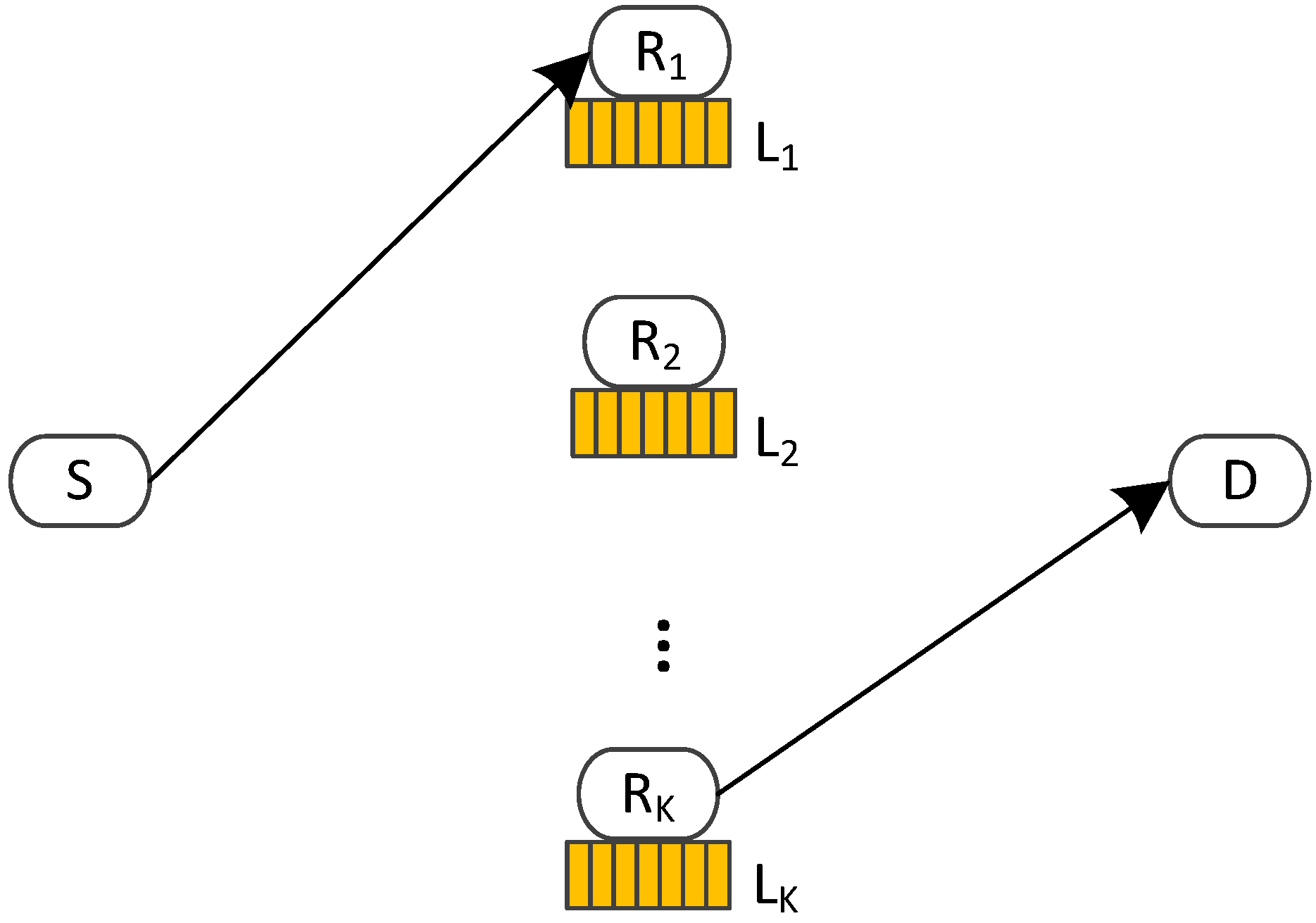
Buffer-aided cooperative relaying is capable of reducing the channel mismatch problem in traditional cooperative relaying to enhance diversity gain and throughput. It gives liberty to pick separate relays for information transfer in contract to traditional relaying which picks a single relay for information transfer. Thus, we can do information processing in the most suitable channel conditions. If source-to-relay channel (C1) is the most suitable, the relay receives and collects data in its buffer. Moreover, if relay-to-destination channel (C2) is most suitable, the relay forwards the collected data to the destination [1,2,3,4].
Buffer-aided cooperative relaying is usually performed in two schedules of transmission, fixed and dynamic. In a fixed schedule, the most suitable C1 based on channel quality or buffer occupancy is picked for data collection at the relay per odd time slot. Similarly, the most fitting C2 is chosen for data forwarding per even time slot. Because of the set communication schedule, the designs following this paradigm achieve maximum diversity gain corresponding to the number of relays [3,5]. In the dynamic schedule, most fitting channel based on channel quality or buffer occupancy is picked either for information processing per time slot. When C1 is most suitable, the corresponding relay collects in its buffer and when C2 is fittest, the corresponding relay forwards from its buffer. The schemes based on dynamic schedule achieve best diversity gain corresponding to twice the number of relays [4,6,7,8]. In this work, our focus is on dynamic schedule.
The advantages of buffer-aided cooperative relaying come with challenges for the system designers, including getting the instant channel state information (CSI), getting the instant buffer occupancy and handling of the extended queuing delay [2]. The most suitable relay is decided based on instantaneous CSI or buffer occupancy. Therefore, it is essential to acquire the CSI of all the channels every time slot. Additionally, in the case of finite buffers, the buffer status monitoring is required to keep track of entirely free or entirely occupied buffers. A filled buffer cannot collect more data and entirely free buffer cannot send data. They are thus making channels inactive. Furthermore, the packet waits in the buffer until its respective C2 is picked for information transfer and it sums up to the queuing delay.
Many efforts have been made in the literature to address the challenges mentioned earlier. The max-max relay selection scheme [3] and Max-Link relay selection scheme [4] are some of the first works in this domain. The link quality, i.e., signal-to-noise ratio (SNR) is the only criteria in these schemes for selection of the most suitable relay. Therefore, they are referred to as SNR-based relay selection schemes. They follow the fixed and dynamic schedules, respectively. Majority of the literature is developed over [3,4]. A priority-based Max-Link relay selection scheme is introduced in [9]. The authors assigned first, second and third priority to full, empty and partially filled buffers, respectively. Relay selection is based on the most powerful channel within a priority class. Similarly, the authors in [10] proposed a hybrid of max-max and Max-Link schemes. In this scheme, the diversity gain of twice the number of relays is obtained using fixed transmission law. In the literature mentioned above, channel quality is the only criteria in relay selection, which has increased the chances of filled or empty buffers. It limits the number of active channels. The drop in the active channels contributes to an increase in the outage probability of the system. Considering this, the authors in [5,7,8,11] propose to select buffer occupancy as the second criteria for relay selection. The schemes viewing buffer occupancy are referred to as buffer state-based relay selection schemes. The authors in [5,7,8] found weight assignment according to the available and occupied buffer space. Channel with the biggest weight is picked for information transfer. The relay choice based on current buffer occupancy considerably increases the number of active channels because it prevents the buffer from being filled or empty. Another approach proposed in [11] considered both the channel quality and buffer occupancy for the choice of the relay. The authors also lessened the queuing delay introduced by buffers by assigning priority to C2 over C1.
To address the latency in a buffer-aided cooperative communication system, the authors in [12] introduce a Max-Link variant that can achieve the perfect delay of only 2 time slots. They propose C2 prioritization over C1 to maintain the shortest possible buffer queues. Another attempt is made in [13]. The authors make use of multiple C1 channels to overcome delays. Yet, these schemes compensated the diversity gains with delay. If the latency is improved, the maximum achievable diversity gain is not attained and if the diversity gain is recovered, the delay is negotiated. Another approach to lessen delay with reduced complexity is presented in [14]. The authors grant priority to C2 while maintaining diversity. They forced a threshold on buffer based on the number of packets. When at least one C1 communication can be made, C2 gets priority only if the buffer fulfills its threshold.
The authors explore [4] using amplify and forward (AF) relaying technique in [15]. This scheme is further studied in [16] using buffer occupancy as a main selection criterion. Another work for buffer-aided cooperative relaying using AF relaying is proposed in [17]. It is designed for single relay node, and it focused on packet selection instead of relay selection to develop the better outage probability. In this scheme, the relay is populated with packets in the first stage. When the buffer is complete with packets, the packet matching is carried out in stage two based on the notion of the channel to packet matching. This concept allows improving the outage probability by providing the packets that passed through adverse C1 move through right C2 and vice versa. This scheme is enhanced in [18] by the inclusion of direct contact between the source and destination and using incremental relaying cooperative diversity technique. The work in [19] considered secrecy performance in buffer-aided cooperative relaying. The secrecy outage performance of buffer-aided multiple-input multiple-output cooperative relaying systems is also investigated in [20] in the proximity of a quiet eavesdropper. The channel with the most beneficial rate is picked to improve the secrecy outage probability. The throughput optimization problem for dual-hop cooperative relay network is also studied in [21]. In this work, the authors claimed that optimal link selection has threshold-based structure and formulate throughput optimization problem using Markov Decision Process.
The literature discloses that the researchers either focused on relay selection or packet selection. To the best of our information, there is no such available literature that simultaneously explores both the relay selection and packet selection for buffer-aided cooperative relaying networks.

Contributions

This work explores relay and packet selection together for buffer-aided CR networks. The contributions are summed as follows:
  • The first scheme known as joint packet and relay selection (JPARS)-SNR is proposed for SNR-based relay selection. The relay selection is carried out first. The most suitable channel based on channel quality is picked for information transfer from all channels. After the relay selection, the packet selection is executed. If the chosen channel is of C2, the scheme picks the best matching from buffers of all relays. The best match is found according to the channel to packet matching notion. According to the condition of C2, the packet that affords the highest end-to-end SNR is picked from the buffer of the corresponding relay. In this design, the overall outage probability of the system is enhanced.
  • JPARS-buffer state-based (BSB) being the second proposed scheme considers current buffer possession in relay selection. The relay with the freest or most occupied buffer space is selected for information processing. The packet selection step is the same as in JPARS-SNR scheme.
  • The proposed JPARS-SNR scheme is simulated for both symmetric and asymmetric channel configurations and investigation for the outage probability, throughput and end-to-end packet delay are presented. The proposed JPARS-BSB scheme is simulated for the symmetric channel configuration using the relay thresholding technique.
  • The results are analyzed with the existing schemes.
The remainder of the article is arranged as follows: Section 2 introduces the various schemes and the motivation for the proposed design. In Section 3, we present our proposed schemes. The numerical results are given in Section 4. The conclusions and future work are shown in Section 5.

2. Relay and Packet Selection Schemes

In this section, we present some of the relevant literature on buffer-aided relay selection and packet selection schemes. Then we extract the motivation for our proposed work. First, we discuss the system model common to relay selection schemes followed by the existing relevant schemes and the proposed scheme.

2.1. Network Model

The cooperative network under study is composed of a source S, a destination D, and a set of relays denoted as R = { R 1 , R 2 , , R K } as shown in Figure 1. All nodes have one antenna and the mode of operation is half-duplex for all the nodes in a network. The relaying technique is AF. There no direct correspondence between S and D because of path-loss and shadowing effects [4,20]. S and D have infinite buffers while all relays are provided with buffers L k of size L (packets) to collect and save the received packet. Buffers support random access mechanism, i.e., they can change their transmission order. They also have the facility of storing both the packet and its SNR. The current buffer occupancy is represented by ψ ( L k ) where 0 ψ ( L k ) L .

2.1.1. Channel Model

All channels encounter independently and identically distributed (i.i.d.) Rayleigh fading as in most of the existing schemes [1,4,7,10,12,20]. The fading envelop of a hop is fixed for a particular time slot and differs from one time slot to another. Moreover, channels also have additive white Gaussian noise (AWGN) with zero mean and N o variance. The channel fading coefficients for C1 and C2 are denoted by h C 1 k and h C 2 k , respectively. The instantaneous SNRs of C1 and C2 are expressed by
γ C 1 k = P | h C 1 k | 2 N 0 , γ C 2 k = P | h C 2 k | 2 N 0
where P is the transmission power of the nodes. The information rate is set to r 0 b/s/Hz.

2.1.2. Transmission Scheme

It is assumed that only 1 packet is sent per time slot. A time slot is a duration in which a packet is transmitted over a link. Each relay buffer is initially empty. If a packet comes into the buffer, buffer size increase by 1, similarly if a packet quits from the buffer, the buffer size decrease by 1. A relay with neither full nor empty buffer can only do information transfer. Therefore, a channel is held active when its communicating buffer is not filled or vacant for C1 or C2, respectively. The distributed method adopted in [20] is used to exchange SNR information so that relays can independently determine which is the fittest relay for data reception and transmission. S broadcasts pilot signal to all relays. Individual relay estimates its SNR between itself and S. After all the relays have received SNR information, a timer is initiated whose worth is inversely equivalent to the estimated SNR. The relay with shortest timer duration finishes first and sends a signal to all the relays declaring itself fittest for data reception among C1. The other relays in the network after listening to this signal back off. Similarly, for C2, all the relays send a pilot signal to destination one by one and the aforementioned distributed method is adopted to know which relay is fittest for data transmission. In this way, the relays themselves can determine which is most suitable, either for data reception or transmission. It is to mention here that the relays with full or empty buffers do not participate in this process. Once all the relays know SNR, relay selection is carried out.
We first briefly discuss some of the most relevant literature as the basis of our proposed work.

2.2. Max-Link Scheme

Max-link [4] relay selection scheme is based on SNR-based relay selection. It uses DF relaying technique with a dynamic regulation for information processing. It picks the most suitable channel among all active channels for reception or transmission. The buffer operates in a first in first out (FIFO) manner. This scheme accomplishes 2 K gain in diversity at a huge buffer size and experiences the delay of 1 + L K time slots.

2.3. AF Max-Link Scheme

AF Max-Link [15] is a maxlink scheme based on AF relaying technique. There is a dynamic transmission regulation. The most suitable channel based on channel quality is picked from all active channels per time slot. If C1 is most suitable, data is collected by the selected relay buffer. If C2 is most suitable, data is amplified and sent from the respective buffer. The buffer operation is FIFO. The gain in diversity of this scheme is same as in Max-Link i.e., 2 K and the delay of 1 + L K time slots is observed.

2.4. AF Packet Selection Scheme

In AF packet selection scheme [17], authors introduced a buffer-aided dual-hop cooperative communication network scheme using a single relay node with AF relaying. This scheme focuses on packet selection instead of relay selection. The scheme functions in two fixed stages. In the first stage, the buffer is populated with the packets. The buffer also collects the information of respective SNR of the data. In the second stage, depending on the SNR of C2, it picks the packet from the buffer to send it to the destination. The packet selection is according to the idea of the channel to packet matching. Unlike Max-Link, the buffer supports random access to the collected data. This scheme reaches the diversity order of 1 and the delay of 2 L time slots.

2.5. Buffer Occupancy-Based AF Scheme

Buffer state-based relay selection scheme based on AF relaying is recommended in [16]. It operates on a dynamic communication paradigm. This scheme takes into account the concurrent activation of various C1 channels for information processing. It also incorporates the AF specific thresholding method at the relay and destination. Priorities are assigned to C1 and C2 according to buffer occupancy. Channel activation at a particular time slot is based on decision algorithm based on seven different cases. It improved the outage probability and queuing delay performance and 2 K gain in diversity is achieved at a short buffer of size 3.

2.6. Motivation for Proposed Work

After analyzing the schemes as mentioned earlier and the other available literature in this domain [5,6,7,8,11], we found out that the work either focuses on relay selection or packet selection. Secondly, all the schemes on relay selection incorporated sequential access buffers (refer to Table 1). When AF relaying technique is used, to satisfy the end-to-end SNR constraint, the overall reliability of the system depends on the most inferior link. Therefore, there exists a chance that the packet lying at the head of the buffer comes from weak C1 and goes from poor C2. The concept of inverse channel packet matching proposed in [17] sounds appealing. However, it is only limited to a single relay and the scheme operation in two segregated phases is a barrier. The buffer is populated with packets in the first phase (one packet per time slot) ignoring the right channel conditions of the C2. In the next phase, the packets from the buffer are transmitted based on the quality of C2 regardless of the excellent channel conditions of C1. Hence, diversity is compromised. If a similar approach is applied on multiple relays without the condition of link selection in two separate phases, the better diversity gain can be achieved.

3. Joint Packet and Relay Selection (JPARS) Schemes

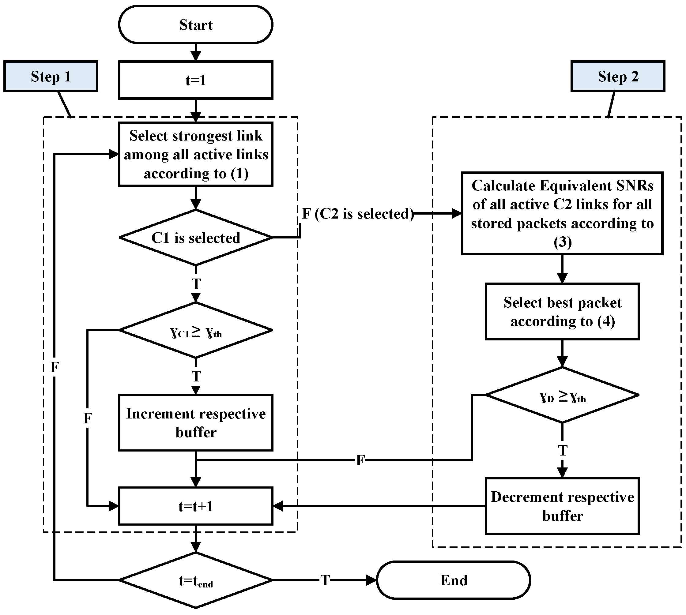
The joint packet and relay selection scheme jointly investigates the relay and packet selection. It is based on the concept of selecting the best relay for data reception and the best packet for data transmission. The scheme operates in two steps. In step 1, the relay selection is performed while in step 2, the packet selection is carried out. It is to mention here that the two steps are not operated in different time slots. Instead, step 2 is initiated only when C2 is chosen in step 1, and it operates in the same time slot to preserve the diversity gain. The flow charts for both the proposed schemes are shown in Figure 2 and Figure 3.

3.1. SNR-Based JPARS Scheme

The first proposed scheme denoted as JPARS-SNR is introduced. This scheme chose the most suitable relay based on the instantaneous SNR of the channel.

3.1.1. Step 1: Relay Selection

In step 1, the most dependable relay based on good channel quality is picked. It is the one having the most powerful channel in terms of SNR among all active channels. Mathematically, the most suitable relay is shown as [4]:
R r = arg max R k R k : ψ ( L k ) 0 { | h C 2 k | 2 } R k : ψ ( L k ) L { | h C 1 k | 2 } .
where R r is the selected relay. If C1 is the fittest, the corresponding relay collects the packet and increments the buffer by 1. The SNR information is also collected in the buffer. Since AF relaying is used, the received signal is not decoded. Instead, it is collected in the corresponding buffer in its amplified form. Step 2 is not initiated in this case, and the relay selection for the next time slot is continued. The packet collected at the relay in the tth time slot is mathematically written as:
y C 1 r ( t ) = P x ( t ) h C 1 r ( t ) + n C 1 r ( t ) ,
where x ( t ) is the transmitted signal, y C 1 r ( t ) is the received signal at the relay R r and n C 1 r ( t ) is the channel noise. On the other hand, if C2 is most suitable, instead of transmitting the packet stored at the front of the buffer queue, the fittest packet is selected in step 2 which is explained in the next subsection.

3.1.2. Phase 2: Packet Selection

Step 2 is meant to execute the packet selection. Step 1 determines whether to receive data at the relay or to begin joint packet and relay selection. The term joint selection is used here because, in this step, the fittest relay is re-selected along with the fittest packet. The purpose of step 1 is only to know which channel to select, i.e., C1 or C2. When the C2 channel is picked based on SNR, the goal is to select which packet of which relay is most suitable for sending. To this goal, the relay and packet selection is jointly performed. The packet selection is based on the notion of the channel to packet matching. The saved packets in the buffer with low SNR leaves the buffer on getting the high SNR of the C2 to improve the overall system performance. Depending on the quality of each active C2, the equivalent SNRs of all the packets collected in the buffers of all the relays are calculated using their saved SNR; they experienced in C1 hop. The equivalent SNR γ D ( t ) for the SNR received at previous qth time slot from the C1 is defined as [22,23]:
γ D ( t ) = | h C 1 ( q ) | 2 | h C 2 ( t ) | 2 | h C 1 ( q ) | 2 + | h C 2 ( t ) | 2 + 1 ,
We define Γ matrix that contains the equivalent SNRs of all the packets stored in the buffer. As an example, the Γ when all the buffers are full is expressed as:
Γ = γ D 11 γ D 12 γ D 1 L γ D 21 γ D 22 γ D 2 L γ D K 1 γ D K 2 γ D K L
The packet with the strongest equivalent SNR is picked for transmission. Mathematically, the joint relay and packet selection is expressed as:
L * = arg max R k l R k l : γ C 1 k l > γ t h γ C 2 k + 1 γ C 2 k γ t h , ψ ( L k ) 0 γ D ,
where L * is the selected packet and R k l { R 1 1 , , R 1 ψ ( L 1 ) , , R K ψ ( L K ) } is the set consisting of all the SNRs currently stored in the buffers of all the relays. γ C 1 k l represents the received SNR of lth packet in a buffer of relay R k received at qth time slot, where q < t . γ C 2 k is the instantaneous SNR at C2 for relay R k . The condition γ C 1 k l > γ t h γ C 2 k + 1 γ C 2 k γ t h ensures that the selected packet is the one that provides equivalent SNR greater than γ t h . It is to mention here that the selected relay in step 2 can be different from the relay selected in step 1. The purpose of re selection of relay in step 2 is to get best available packet for transmission which in turn reduces the overall outage probability. The packet received at D is mathematically expressed as:
y C 2 s ( t ) = P G y C 1 ( q ) h C 2 s ( t ) + n C 2 s ,
where R s is the relay whose packet is selected, y C 2 s ( t ) is the received signal at D, n C 2 s ( t ) is the channel noise and G is the gain factor defined as [22]:
G = P P h C 1 ( q ) 2 + N 0
The outage is considered in the JPARS-SNR scheme when no packet is picked for transmission, i.e., L * = ϕ . It is the case when there is not a single packet in the buffer that provides equivalent SNR higher than the predefined threshold value γ t h , where γ t h = 2 2 r 0 1 . γ t h is the minimum threshold for the data to be decode-able at D. Mathematically, the outage probability of a packet is expressed as:
P o u t S N R = P ( γ D γ t h ) .
Any packet whose equivalent SNR at the destination falls below γ t h is considered in an outage. In case of an outage, the packet stays in the buffer, and buffer status remains unchanged. On the other hand, if the maximum equivalent SNR is higher than γ t h , the chosen packet is sent to the destination, and the corresponding buffer size is decreased by 1.

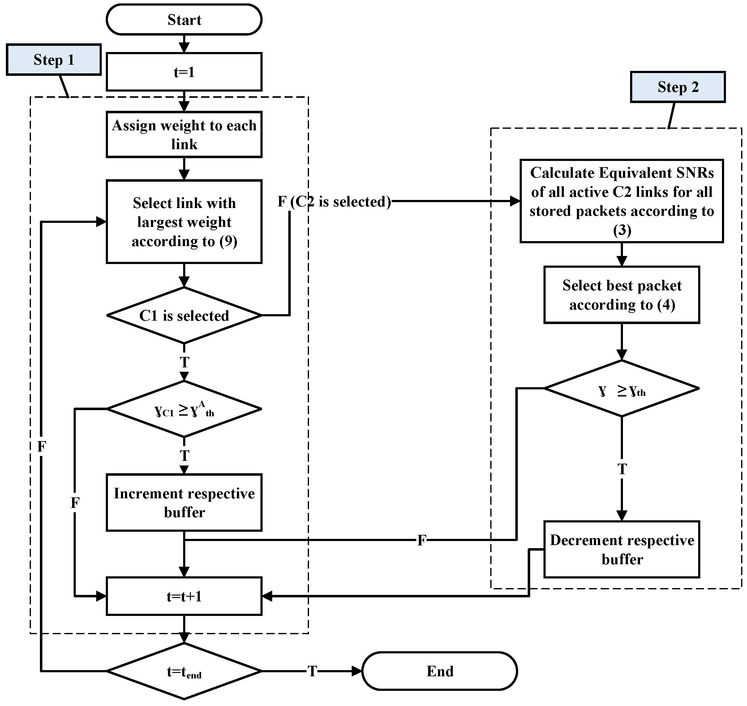
3.2. Buffer State-Based Relay and Packet Selection

The SNR-based relay selection ignores the buffer occupancy, which commences the problem of crowded or blank buffers. It, in turn, reduces the number of active channels. In this section, a scheme for buffer occupancy-based relay and packet choice is presented. The operation of the scheme is similar to JPARS-SNR scheme. Step 1 picks the most suitable relay and step 2 picks the fittest packet.

3.2.1. Step 1: Relay Selection

Step1 is meant to execute relay selection. In this scheme, each channel is assigned an appropriate weight. The weight is according to the available or occupied buffer space in the corresponding buffer for reception or transmission, respectively. Let w be the vector containing weights of all links.
w = { w 1 , w 2 , , w 2 K } .
The length of w is 2 K . w i = L ψ ( L k ) are the weights of the channels on C1 side if 1 i K and w i = ψ ( L k ) are the weights of the channels on C2 side if K + 1 i 2 K . For instance, with K = 2 and L = 2 , w = { w 1 , w 2 , w 3 , w 4 } . w 1 and w 2 are the weights of C1 channels and w 3 and w 4 are the weights of C2 channels. If L 1 has 2 packets, w 1 = 0 and w 3 = 2 . The channel with the largest weight is picked for information transfer. The relay selection is mathematically expressed as [7],
R r ¯ = arg max R k R k : ψ ( L k ) L , | h C 1 k | 2 > γ t h A { L ψ ( L k ) } R k : ψ ( L k ) 0 , | h C 2 k | 2 > γ t h A { ψ ( L k ) } .
where R r ¯ is the selected relay for reception or transmission. There is a possible scenario when multiple links have the same maximum weights. In such a case, one channel is randomly selected among the channels with largest weight. Here γ t h A is the threshold at relay for AF relaying to avoid noise propagation. This threshold technique is introduced in [16]. In AF relaying, data is not decode-able at the relay. In buffer-aided CR based on AF relaying, the signal is not checked against acceptable threshold SNR at the relay. Instead, amplified signal along with noise is transmitted and end-to-end equivalent SNR is checked against SNR threshold at the destination only. Therefore, the quality of the signal at the destination depends on the poorest channel. To avoid noise propagation, we adopt thresholding at the relay and destination node. If the signal is below threshold γ t h A , it is not stored in the buffer. The expression of γ t h A considering the symmetric case, i.e., γ ¯ C 1 = γ ¯ C 2 = γ ¯ , γ D = 2 2 r o 1 and using (3), is given as,
γ = 2 2 r o 1 + 2 2 r o ( 2 2 r o 1 )
where γ = γ t h A , which is the thresholding SNR at the relay and destination. If the relay is picked for the reception, the data is collected in the respective buffer, and buffer size is increased by 1. On the other hand, if the relay is picked for transmission, step 2 is initiated for packet selection. The outage is considered when none of the channels have SNR greater than γ t h A . In that case, R r = 0 . The outage in step 1 is expressed as,
P o u t B S B = P ( γ C 1 γ t h A ) P ( γ C 2 γ t h A )

3.2.2. Step 2: Packet Selection Selection

The packet selection in buffer state-based JPARS scheme is the same as in SNR-based JPARS scheme. The packet that provides the highest end-to-end equivalent SNR is selected for transmission.
The outage is considered in JPARS-BSB scheme when no packet is available that provides equivalent SNR higher than the threshold, which is similar to JPARS-SNR scheme.

3.3. Buffer Access

The buffer access method is considered to be random in the proposed scheme. Initially, all the buffers are empty and only the C1 channels are active. Therefore, the packets are stored in the buffer on the first-come, first-served basis. The first packet is collected and saved at the first location of the selected buffer. If in the subsequent time slot, the same C1 channel is picked, the packet is stored at the second available location and so on. When C2 can contribute, the best packet is selected for data transmission. The best packet is not necessarily placed at the head. Instead, it can be any location inside the buffer. Therefore, an empty location is created between two filled buffer locations. In this case, the packet arrives at the first available space and departs from any location. REMARK: According to the proposed scheme, the most suitable reception relay is picked out of K C1 channels and K C2 channels in step 1. Furthermore, in step 2, the most suitable packet is selected out of K × L SNRs (in the worst case) stored in the buffers. Therefore, the overall complexity of the proposed scheme is 2 K + K L .

4. Numerical Results

We assess the performance of JPARS-SNR and JPARS-BSB schemes for the outage probability, throughput and packet delay. The proposed schemes are compared with AF Max-Link scheme [15] and AF-dual-hop scheme [17]. r 0 is fixed at 1 b/s/Hz everywhere in the simulations and the number of relays and buffer size is explicitly mentioned for each result. Rayleigh fading is used to map channel gains and AWGN is used to map noise with unit variance and zero mean. The transmit powers of source and relay are considered equal as considered in the relevant literature [7,15]. The 10 6 runs are performed using Monte Carlo simulations. The evaluation for the symmetric and asymmetric channels are presented for the analysis of JPARS-SNR scheme, and the only symmetric case is presented for the analysis of JPARS-BSB scheme.

4.1. Outage Probability: Symmetric Channel Conditions γ ¯ C 1 = γ ¯ C 2 = γ ¯

In this segment, we evaluate the outage probability performance in the case of symmetric channel configuration when γ ¯ C 1 = γ ¯ C 2 = γ ¯ , where γ ¯ is the average SNR of a channel. The results are presented for the outage probability of proposed schemes in comparison to the existing schemes, the outage probability on growing the relay count and the outage probability when expanding the buffer size.
Figure 4 presents the outage probability analysis of the proposed JPARS-SNR and JPARS-BSB schemes and the two other schemes: AF Max-Link and AF-dual-hop versus the average SNR. In this plot, for K = 1 and L = 2 , the AF Max-Link and JPARS-SNR schemes behave identically. Although the AF Max-Link and AF-dual-hop schemes both have similar system models in this setup, the performance of AF-dual-hop is worse because it operates in two segregated phases that prevent it from increasing its diversity gain. On growing the relays, the packet selection shows its impact on the performance. The notion of a channel to packet matching helps to enhance the performance. At K = 2 and L = 8 , the diversity gain of AF Max-Link is 41.804 36.16 20 17.5 = 2.25 and that of JPARS-SNR is 44.43 38.53 20 17.5 = 2.36 . The proposed scheme achieves 0.11 dB improvement in the diversity gain. It is to note here that the improvement is not in a significant amount because the diversity is gained by rising the active channels. Moreover, the number of active channels is increased by avoiding full or empty buffers. The JPARS-SNR scheme chooses a channel based on SNR only. Therefore, the problem of full or empty buffers at small buffer size persists. Selecting the relay considering the buffer status as well as packet selection in JPARS-BSB scheme improves the outage probability. Initially, the performance of JPARS-BSB is close to AF Max-Link scheme; however, at big SNR, the achievement of JPARS-BSB is significantly improved.
Figure 5 tells the outage probability achievements for JPARS-SNR and JPARS-BSB schemes w.r.t average SNR i.e., γ ¯ . In this plot, the buffer size of L is fixed at 3, and the number of relays is varied from 1 to 5. The results show that by growing relays in number, the outage probability for both the schemes is lowered and hence, the gain in diversity is raised. It is also observed that at the small SNR, the performance of both the schemes is almost identical. However, at large SNR (above 12 dB), the JPARS-BSB leads. Also, when the number of relays is small, JPARS-BSB shows better outage probability as compared to JPARS-BSB.
In Figure 6, to extend the investigation, the outage probability performance is presented for the growing buffer size with fixed relays at K = 2 . The buffer size is raised from 1 to to get the outage probability bound. We noted that growing the buffer size overcomes the outage probability. The drop in the performance is because of the rise in the active channels. Larger the buffer size, less is the possibility of void or congested buffer. The full gain in diversity, i.e., 2 K , is achieved at a considerable value of buffer size.
Figure 7 shows the behavior of JPARS-BSB scheme for increasing buffer size when the relays are set at K = 2 . Extending buffer size from L = 1 to L = 3 shows improvement in outage probability. The further increase in buffer size has no impact on outage probability. Also, on increasing the buffer size, packet selection does not have a prominent influence on the overall outage performance because the outage probability is dominated by space diversity instead of packet diversity. The JPARS-BSB scheme approaches the bound at a tiny buffer size in comparison to JPARS-SNR scheme.

4.2. Outage Probability: Asymmetric Channel Conditions γ ¯ C 1 = α γ ¯ and γ ¯ C 2 = β γ ¯

Now we judge the outage probability performance of JPARS-SNR in the asymmetric channel configuration. The average channel SNRs of C1 and C2 are γ ¯ C 1 = α γ ¯ and γ ¯ C 2 = β γ ¯ , respectively, where β and α are real and positive quantities.
In Figure 8 the outage probability results are presented for α = 2 and 3 , β = 1 , K = 2 and 3 and L is fixed at 4. It is observed that both the schemes obtain the reduced gain in diversity on prioritizing C1. The improvement in C1’s SNR raises the possibility that the relay is picked for data reception. Thus, the quantity of packets entering the buffer is more than the number of packets leaving the buffer, hence, increasing the number of full buffers. The full buffers reduce the number of active channels, and the outage probability is increased. It is also seen that the JPARS-SNR scheme is showing slightly better results than AF Max-Link scheme when C1 is prioritized by a factor of 2 and 3. However, the improvement is minimal. All the packets in the buffer have high SNR they experienced in C1; therefore, the packet selection is not making much difference.
Figure 9 presents the asymmetric outage probability performance when the C2 is prioritized over C1. In this plot, α = 1 , β = 2 and 3 , K = 2 and 3 and L is fixed at 4. It is observed that when β = 2 , the JPARS-SNR scheme shows a slightly better performance in relation to the AF Max-Link scheme both for K = 2 and 3 ; however, when β = 3 , the JPARS-SNR scheme almost overlaps with AF Max-Link scheme. The reason for such behavior is explained as follows: when C2 is prioritized, the quantity of packets leaving the buffer is more as compared to the ones entering the buffer. It keeps the buffer queues as short as possible because as soon as the packet enters the buffer, it leaves most probability in the next time slot. It is the reason that both schemes are showing similar performance, and the packet selection is not producing the improvement in the outage probability. The diversity gain is also reduced because of a similar reason.

4.3. Average Throughput

To extend the analysis, we have also presented the throughput of the proposed schemes. Figure 10 presents the average throughput of JPARS-SNR, JPARS-BSB and AF Max-Link schemes for K = 2 and L = 3 . It is observed that the schemes with lower outage probability show better throughput. JPARS-BSB shows best throughput because it avoids full and empty buffers and keep maximum number of links in active state. Since half-duplex relays are used, therefore, the maximum achievable throughput is 0.5 .
Figure 11 shows the average through of JPARS-SNR scheme when the channel conditions are asymmetric. For this result, K = 2 , L = 3 , and { α , β } are set to {1,3} and {3,1}. The plot clearly shows that when β = 3 , i.e., C2 is prioritize over C1, throughput is significantly large as compared to the case when C1 is prioritized over C2.

4.4. Packet Delay

In this subsection, the packet delay of the JPARS-SNR and JPARS-BSB schemes are analyzed and compared with the AF Max-Link scheme. We analyze it for maximum and minimum delay a packet faces when it enters and leaves the buffer. The source is assumed to have an infinite buffer size and it always has a packet to send. Therefore, the delay from C1 is considered to be 1 time slot. The buffer at the relay node introduces considerable buffering delays. We presented the end-to-end maximum and minimum value of packet delay in Table 2 and Table 3.
Table 2 presents the packet delay for symmetric channel configuration at γ ¯ = 20 dB for 500,000 packets. It is evident from these readings that the maximum delay a packet faced in the proposed JPARS-SNR scheme is less than the AF Max-Link scheme. This is because the JPARS-SNR picks the packet from the buffer (the packet the gives the highest equivalent SNR) for transmission, whereas, AF Max-Link scheme transmits packet resting at the start of the queue. The minimum delay in all the schemes is 2 time slots regardless of K and L. At K = 3 and L = 8 , the JPARS-SNR scheme achieves 27% less delay as compared to AF Max-Link scheme. In JPARS-BSB scheme, the maximum delay is less than both JPARS-SNR and AF Max-Link schemes. This is because the JPARS-BSB scheme selects C2 based on buffer occupancy. Therefore, the packets do not wait for long in a buffer. For K = 3 , the JPARS-BSB scheme has similar values for the maximum delay as for K = 2 . It shows that rising L does not linearly rise delay in the buffer state-based scheme. Hence, by the joint exploration of relay and packet selection, both the diversity and delay are improved.
In Table 3, the delay analysis for the asymmetric channel configuration is presented for the two cases α = 2 and β = 2 , at L = 2 and 8 , K = 2 and γ ¯ = 20 dB. These values are calculated for 500,000 packets from the source node. It is concluded from the readings that when the C1 link is prioritized over C2 by a factor of 2, the delay is increased as compared to symmetric channel configuration. Increasing the SNR of C1 increases the possibility that the packet stays in the buffer for many time slots because of the selection probability of C2 decreases. Therefore, the number of time slots at L = 8 is very high as compared to L = 8 for symmetric channel conditions. Furthermore, there is a significant difference in the delay of the JPARS-SNR scheme and AF Max-Link scheme at both values of L. JPARS-SNR shows comparatively less maximum delay than AF Max-Link. The minimum time slots stay the same in asymmetric channels too.
Interestingly, when the C2 is prioritized over C1 by a factor of 2, the delay in both the schemes are not making too much difference. When C2 has high SNR, its selection probability increases, and data leaves the buffer as soonest possible. Therefore, the buffer queues are very short. With the short buffer queues, the packet selection scheme and non-packet selection schemes do not make too much difference both in the delay and diversity gain. Furthermore, the delay, in this case, is very less as compared to symmetric channel readings. The reason for less delay is the reduction in the diversity gain (see Figure 9).

5. Conclusions and Future Works

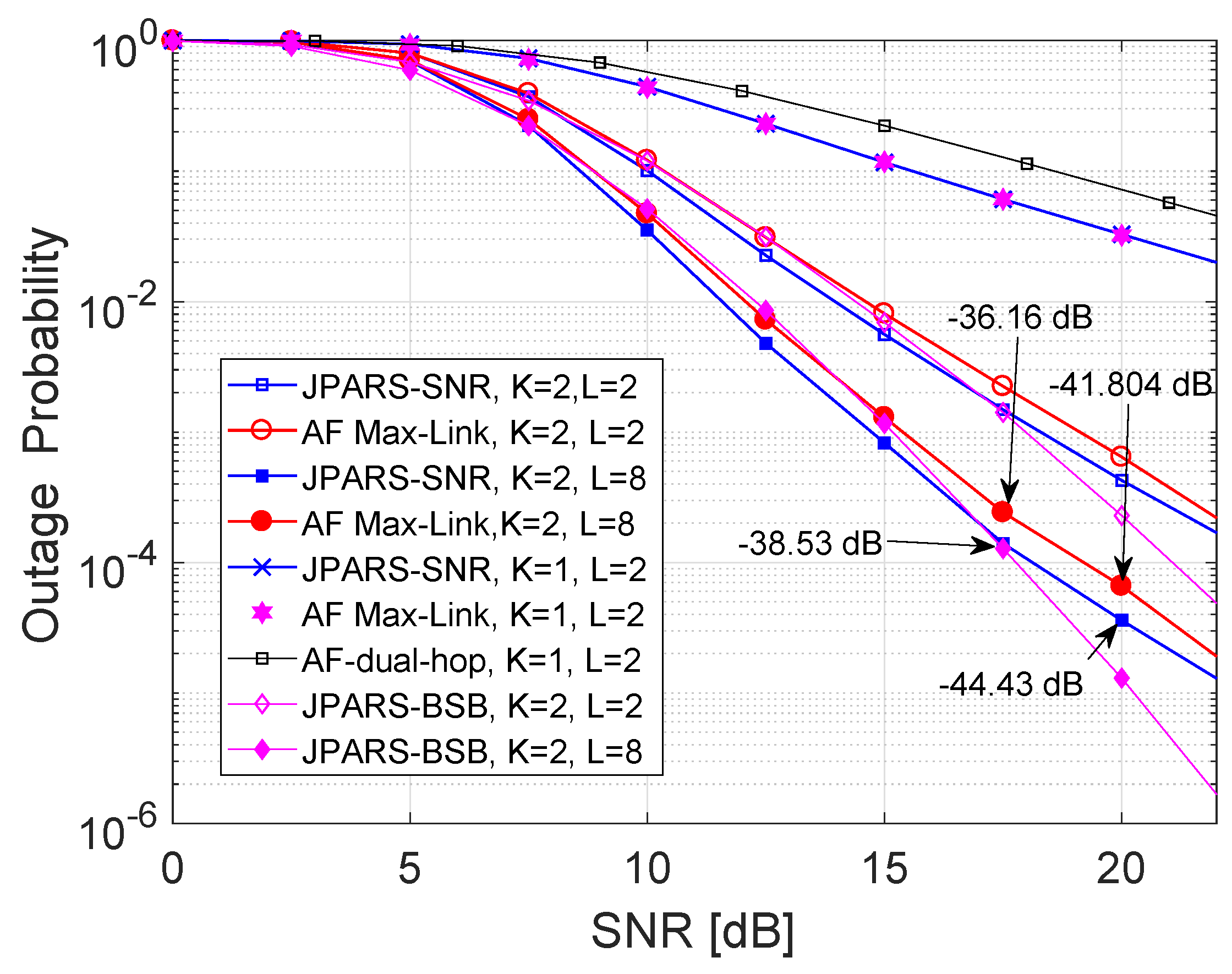
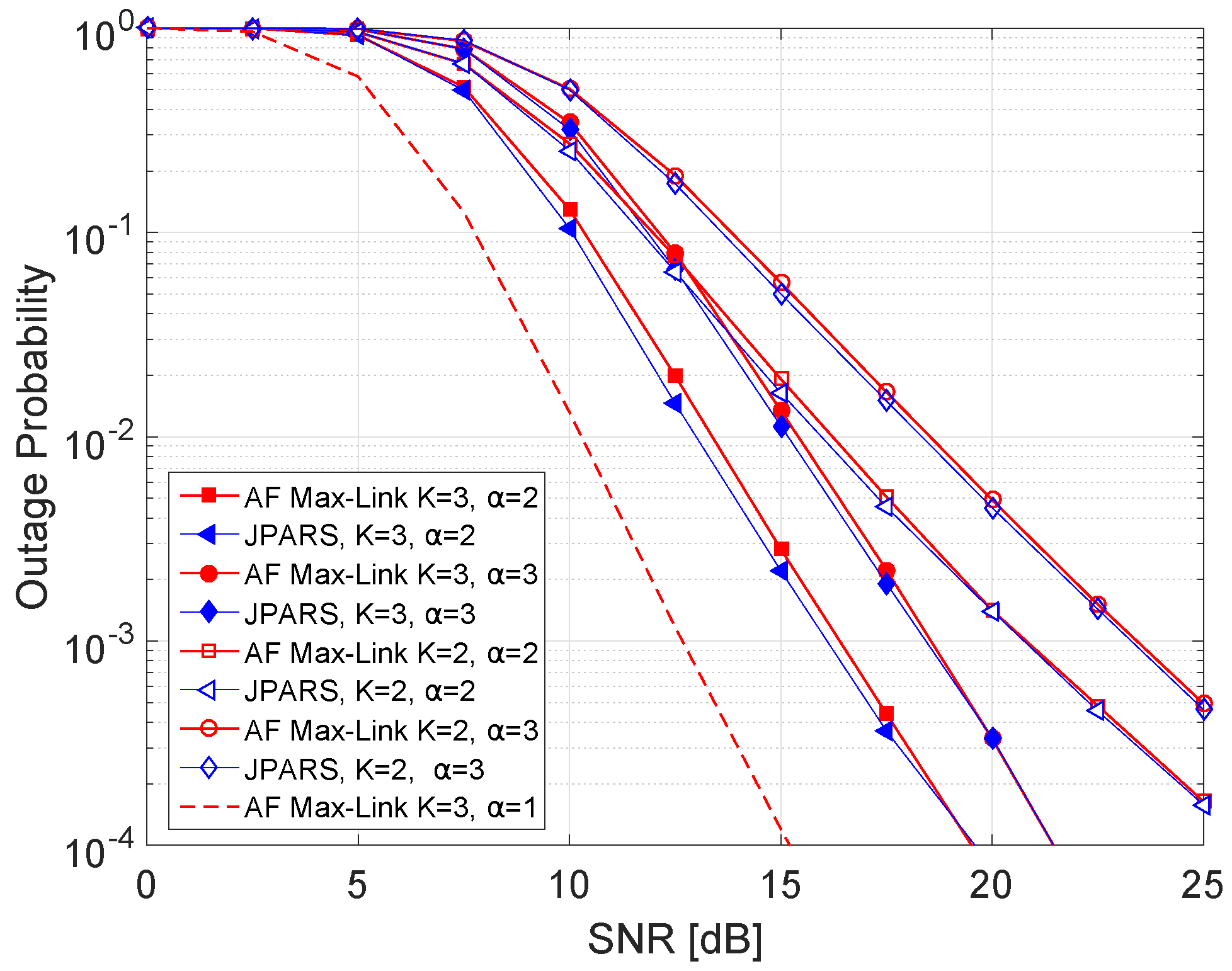
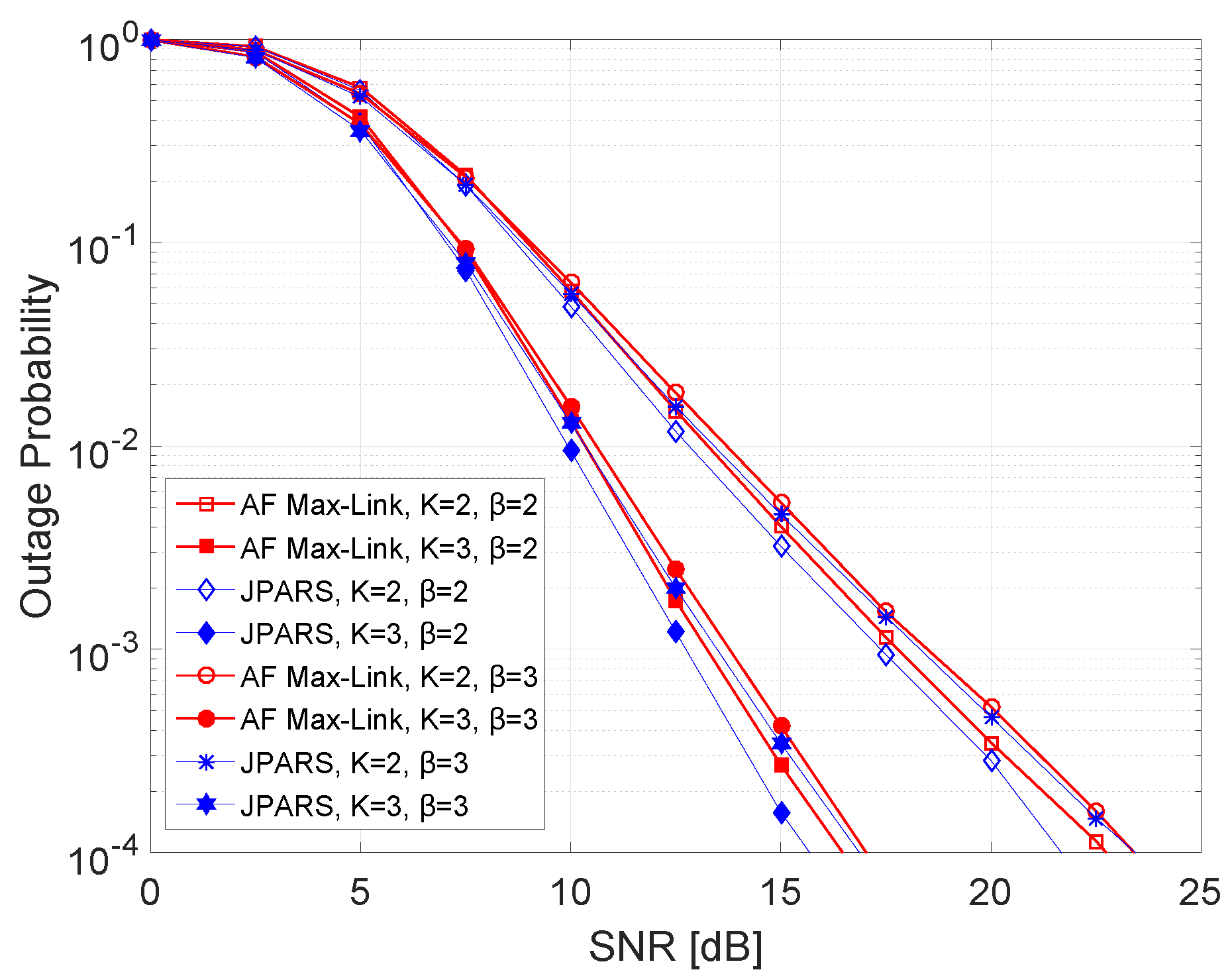
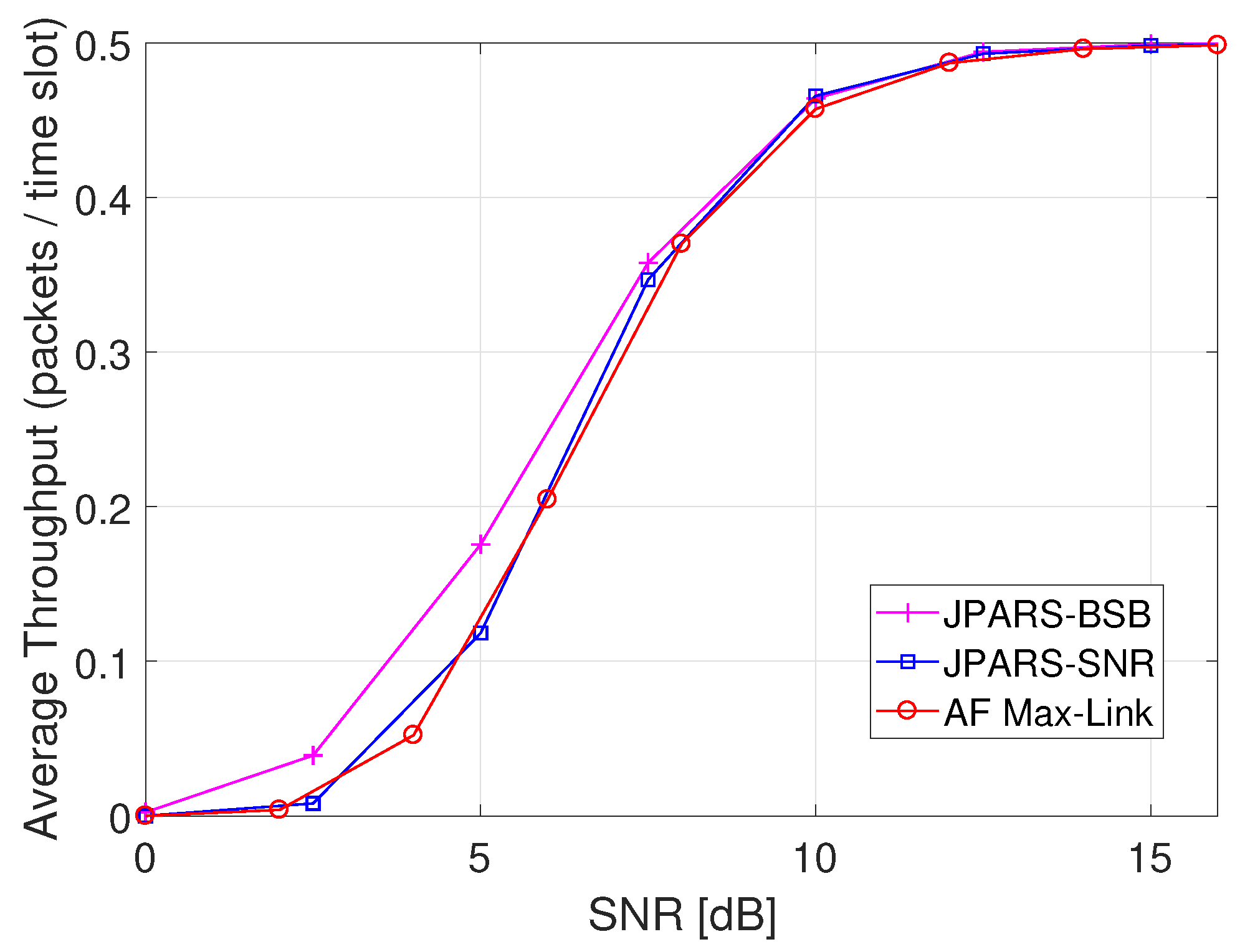
In this article, we jointly explore the relay and packet selection and proposed two schemes known as JPARS-SNR and JPARS-BSB. The idea of packet selection over multiple relays improved the overall outage probability of the system. The simulation outcomes show that the JPARS-BSB scheme is better in terms of outage probability as compared to JPARS-SNR scheme. It is concluded that in the JPARS-SNR scheme, the symmetric channel configuration gives a better outage probability as compared to the asymmetric channel configuration. When the SNR of C2 is higher than the SNR of C1, the proposed schemes perform better for small values of β . However, when β is increased, AF Max-Link and JPARS-SNR schemes have the same performance. When the SNR of C2 is less than the SNR of C1, the proposed scheme is not making much difference in the outage probability. Similar observations hold true for throughput. The maximum packet delay of JPARS-SNR is below AF Max-Link both in the symmetric and asymmetric channel conditions; however, when C2 is given priority over C1, the improvement in the delay is not very significant. The delay in JPARS-BSB scheme is not increasing linearly as in JPARS-SNR and AF Max-Link schemes. Additionally, in the case of asymmetric channel conditions, since JPARS-BSB perform relay selection on the basis of buffer status, we can conclude that JPARS-SNR can be used to prioritize the relay-destination links for better average delay. In the future, we intend to investigate joint packet and relay selection for non-orthogonal multiple access communication.

Author Contributions

All authors discussed and agreed on the idea and scientific contribution. H.N. and N.J. proposed the idea and wrote system model. They also performed simulations and wrote simulation section. W.R. did mathematical modeling in the manuscript. M.S. contributed in manuscript writing and revisions. All authors have read and agreed to the published version of the manuscript.

Funding

This work was supported by the National Research Foundation of Korea (NRF) through the Brain Korea 21 Plus Program under Grant 22A20130012814.

Conflicts of Interest

The authors declare no conflict of interest.

References

  1. Bletsas, A.; Khisti, A.; Reed, D.P.; Lippman, A. A simple Cooperative diversity method based on network path selection. IEEE J. Sel. Areas Commun. 2006, 24, 659–672. [Google Scholar] [CrossRef] [Green Version]
  2. Zlatanov, N.; Ikhlef, A.; Islam, T.; Schober, R. Buffer-aided cooperative communications: Opportunities and challenges. IEEE Commun. Mag. 2014, 52, 146–153. [Google Scholar] [CrossRef]
  3. Ikhlef, A.; Michalopoulos, D.S.; Schober, R. Max-Max Relay Selection for Relays with Buffers. IEEE Trans. Wirel. Commun. 2012, 11, 1124–1135. [Google Scholar] [CrossRef]
  4. Krikidis, I.; Charalambous, T.; Thompson, J.S. Buffer-aided relay selection for cooperative diversity systems without delay constraints. IEEE Trans. Wirel. Commun. 2012, 11, 1957–1967. [Google Scholar] [CrossRef]
  5. Lin, S.L.; Liu, K.H. Relay selection for cooperative relaying networks with small buffers. IEEE Trans. Veh. Technol. 2016, 65, 6562–6572. [Google Scholar] [CrossRef]
  6. Charalambous, T.; Nomikos, N.; Krikidis, I.; Vouyioukas, D.; Johansson, M. Modeling buffer-aided relay selection in networks with direct transmission capability. IEEE Commun. Lett. 2015, 19, 649–652. [Google Scholar] [CrossRef]
  7. Xu, P.; Ding, Z.; Krikidis, I.; Dai, X. Achieving Optimal Diversity Gain in Buffer-Aided Relay Networks With Small Buffer Size. IEEE Trans. Veh. Technol. 2016, 65, 8788–8794. [Google Scholar] [CrossRef]
  8. Raza, W.; Javaid, N.; Nasir, H.; Alrajeh, N.; Guizani, N. Buffer-Aided Relay Selection with Equal-Weight Links in Cooperative Wireless Networks. IEEE Commun. Lett. 2017. [Google Scholar] [CrossRef]
  9. Manoj, B.R.; Mallik, R.K.; Bhatnagar, M.R. Performance Analysis of Buffer-Aided Priority-Based Max-Link Relay Selection in DF Cooperative Networks. IEEE Trans. Commun. 2018, 66, 2826–2839. [Google Scholar] [CrossRef]
  10. Oiwa, M.; Tosa, C.; Sugiura, S. Theoretical Analysis of Hybrid Buffer-Aided Cooperative Protocol Based on Max–Max and Max–Link Relay Selections. IEEE Trans. Veh. Technol. 2016, 65, 9236–9246. [Google Scholar] [CrossRef]
  11. Luo, S.; Teh, K.C. Buffer State Based Relay Selection for Buffer-Aided Cooperative Relaying Systems. IEEE Trans. Wirel. Commun. 2015, 14, 5430–5439. [Google Scholar] [CrossRef]
  12. Tian, Z.; Gong, Y.; Chen, G.; Chambers, J. Buffer-aided Relay Selection with Reduced Packet Delay in Cooperative Networks. IEEE Trans. Veh. Technol. 2016. [Google Scholar] [CrossRef] [Green Version]
  13. Oiwa, M.; Sugiura, S. Reduced-Packet-Delay Generalized Buffer-Aided Relaying Protocol: Simultaneous Activation of Multiple Source-to-Relay Links. IEEE Access 2016, 4, 3632–3646. [Google Scholar] [CrossRef]
  14. Nomikos, N.; Charalambous, T.; Vouyioukas, D.; Karagiannidis, G.K. Low-Complexity Buffer-Aided Link Selection with Outdated CSI and Feedback Errors. IEEE Trans. Commun. 2018. [Google Scholar] [CrossRef]
  15. Tian, Z.; Chen, G.; Gong, Y.; Chen, Z.; Chambers, J.A. Buffer-Aided Max-Link Relay Selection in Amplify-and-Forward Cooperative Networks. IEEE Trans. Veh. Technol. 2015, 64, 553–565. [Google Scholar] [CrossRef] [Green Version]
  16. Oiwa, M.; Nakai, R.; Sugiura, S. Buffer-State-and-Thresholding-Based Amplify-and-Forward Cooperative Networks. IEEE Wirel. Commun. Lett. 2017, 6, 674–677. [Google Scholar] [CrossRef]
  17. Li, G.X.; Dong, C.; Liu, D.; Li, G.; Zhang, Y. Outage Analysis of Dual-Hop Transmission with Buffer Aided Amplify-and-Forward Relay. In Proceedings of the 2014 IEEE 80th Vehicular Technology Conference (VTC2014-Fall), Vancouver, BC, Canada, 14–17 September 2014; pp. 1–5. [Google Scholar] [CrossRef] [Green Version]
  18. Nasir, H.; Javaid, N.; Raza, W.; Imran, M.; Guizani, M. Performance analysis of a buffer-aided incremental relaying in cooperative wireless network. In Proceedings of the 2017 13th International Wireless Communications and Mobile Computing Conference (IWCMC), Valencia, Spain, 26–30 June 2017; pp. 1483–1488. [Google Scholar]
  19. Chen, G.; Tian, Z.; Gong, Y.; Chen, Z.; Chambers, J.A. Max-Ratio Relay Selection in Secure Buffer-Aided Cooperative Wireless Networks. IEEE Trans. Inf. Forensics Secur. 2014, 9, 719–729. [Google Scholar] [CrossRef] [Green Version]
  20. Tang, X.; Cai, Y.; Huang, Y.; Duong, T.Q.; Yang, W.; Yang, W. Secrecy Outage Analysis of Buffer-Aided Cooperative MIMO Relaying Systems. IEEE Trans. Veh. Technol. 2018, 67, 2035–2048. [Google Scholar] [CrossRef]
  21. Zhou, B.; Cui, Y.; Tao, M. Stochastic Throughput Optimization for Two-Hop Systems With Finite Relay Buffers. IEEE Trans. Signal Process. 2015, 63, 5546–5560. [Google Scholar] [CrossRef] [Green Version]
  22. Hasna, M.O.; Alouini, M.S. End-to-end performance of transmission systems with relays over Rayleigh-fading channels. IEEE Trans. Wirel. Commun. 2003, 2, 1126–1131. [Google Scholar] [CrossRef] [Green Version]
  23. Laneman, J.N.; Wornell, G.W. Energy-efficient antenna sharing and relaying for wireless networks. In Proceedings of the 2000 IEEE Wireless Communications and Networking Conference, Conference Record (Cat. No. 00TH8540), Chicago, IL, USA, 23–28 September 2000; Volume 1, pp. 7–12. [Google Scholar]
Figure 1. Proposed network model of JPARS scheme.
Symmetry 12 00241 g001
Figure 2. Flow chart of SNR-based JPARS scheme.
Symmetry 12 00241 g002
Figure 3. Flow chart of buffer state-based JPARS scheme.
Symmetry 12 00241 g003
Figure 4. Outage probability of the proposed JPARS, AF Max-Link and AF-dual-hop schemes with the combinations of (K,L) as (1,2), (2,2) and (2,8).
Symmetry 12 00241 g004
Figure 5. Outage probability of the proposed JPARS schemes for L = 3 with the increasing number of relays.
Symmetry 12 00241 g005
Figure 6. Outage probability of the proposed JPARS-SNR-based scheme for K = 2 with the increasing buffer size.
Symmetry 12 00241 g006
Figure 7. Outage probability of the proposed JPARS-buffer state-based-based scheme for K = 2 with the increasing buffer size.
Symmetry 12 00241 g007
Figure 8. Outage probability of the proposed JPARS-SNR scheme when C1 is prioritized for L = 4 , K = 2 and 3 , α = 2 and 3 and β = 1 .
Symmetry 12 00241 g008
Figure 9. Outage probability of the proposed JPARS-SNR scheme when C2 is prioritized for L = 4 , K = 2 and 3 , α = 1 and β = 2 and 3 .
Symmetry 12 00241 g009
Figure 10. Average throughput of the proposed schemes for K = 2 and L = 3 .
Symmetry 12 00241 g010
Figure 11. Average throughput of the proposed schemes for K = 2 and L = 3 in asymmetric channel conditions.
Symmetry 12 00241 g011
Table 1. Comparison on relay selection and packet selection schemes in buffer-aided cooperative relaying.
Sr.SchemeRelaying TechniqueRelay SelectionPacket SelectionBuffer Access
1Max-LinkDFYesNoFIFO
2AF Max-LinkAFYesNoFIFO
3AF-dual-hopAFNoYesRandom
4AF buffer state-basedAFYesNoFIFO
5JPARS-SNRAFYesYesRandom
6JPARS-BSBAFYesYesRandom
Table 2. Comparison on packet delay of JPARS-SNR, JPARS-BSB and AF Max-Link schemes for symmetric channel conditions γ ¯ = 20 dB.
AF Max-LinkJPARS-SNRJPARS-BSB
Max.Min.Max.Min.Max.Min.
K = 2 L = 2 802602512
L = 8 1094286224782
K = 3 L = 2 13221072522
L = 8 15302110724892
Table 3. Comparison on maximum and minimum packet delay of JPARS-SNR and AF Max-Link schemes for K = 2 and asymmetric channel conditions γ ¯ C 1 = α γ ¯ , γ ¯ C 2 = β γ ¯ .
AF Max-LinkJPARS-SNR
Max.Min.Max.Min.
α = 2 , β = 1 L = 2 17621412
L = 8 43,214236,7282
α = 1 , β = 2 L = 2 422392
L = 8 12021032

