Numerical Investigation of a Foundation Pit Supported by a Composite Soil Nailing Structure

 , and
, and
Abstract
:1. Introduction
2. Project Overview
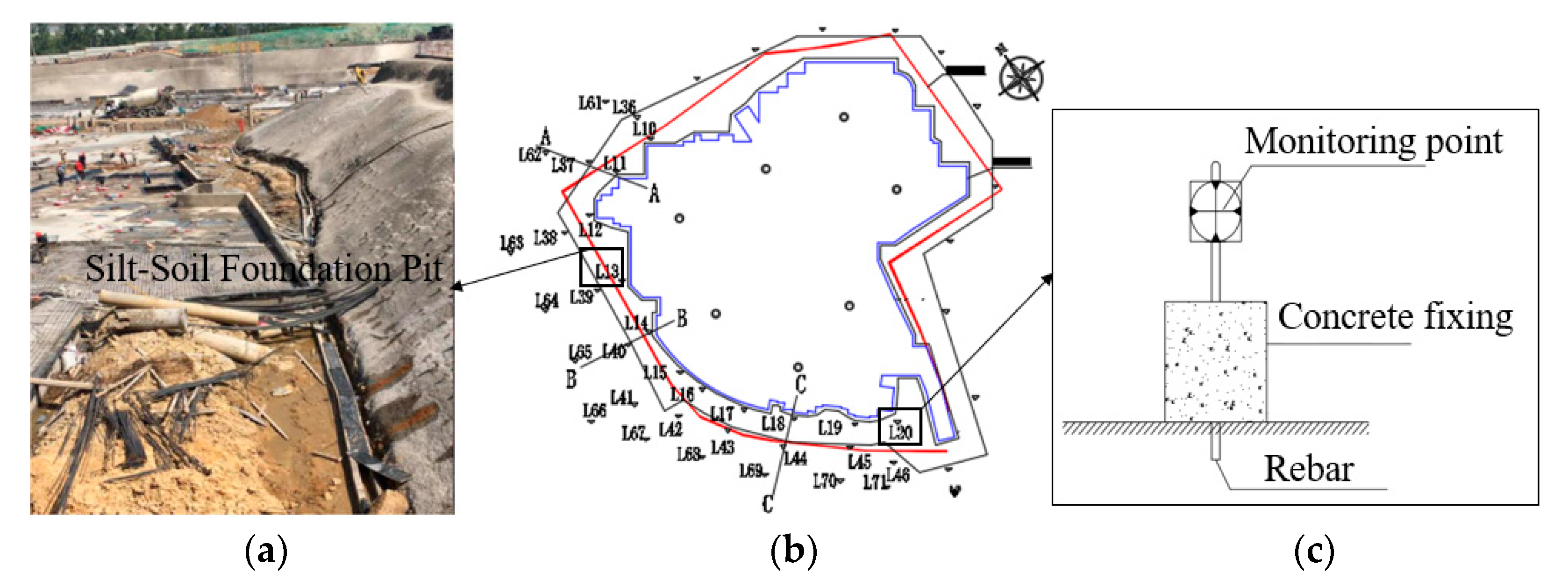
2.1. Background
2.2. In Field Monitoring
2.2.1. Horizontal Displacement
2.2.2. Vertical Settlement
3. Factors Affecting Stability
3.1. Numerical Model
3.2. Orthogonal Test
3.3. Design of the Orthogonal Test
3.4. Orthogonal Test Results
4. Numerical Results
4.1. Vertical Displacement
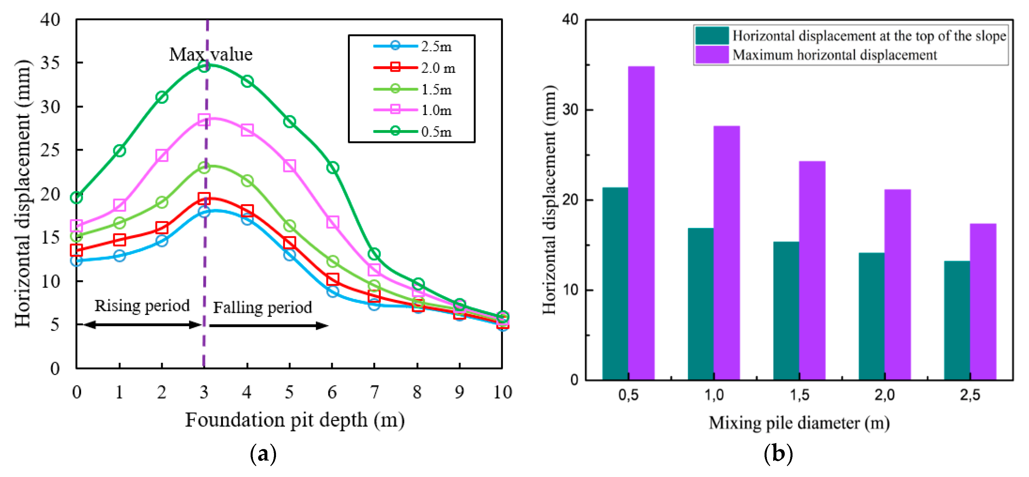
4.2. Horizontal Displacement
4.3. Axial Force of Soil Nailing
4.4. Foundation Pit Stability
5. Deformation Characteristics
5.1. Effect of Soil Nails on Deformation
5.1.1. Inclination Angles of Soil Nails
5.1.2. Prestressing of Soil Nails
5.2. Effect of Mixing Pile on Deformation
5.2.1. Diameter of the Mixing Pile
5.2.2. Embedded Depth of the Mixing Pile
5.2.3. Mixing Pile Position from the Excavation Surface
6. Conclusions
Author Contributions
Funding
Conflicts of Interest
References
- Cheng, Y.M.; Au, S.K.; Yeung, A.T. Laboratory and Field Evaluation of Several Types of Soil Nails for Different Geological Conditions. Can. Geotech. J. 2016, 53, 634–645. [Google Scholar] [CrossRef]
- Peng, W.; Xie, Y.; Xu, S.; Wang, Y.; Qian, H. Experimental study on working behavior of prestressed anchor composite soil nailing wall. J. Cent. South Univ. (Nat. Sci. Ed.) 2015, 46, 1468–1474. [Google Scholar]
- Qin, S.; Chen, H.; Zhang, M. Numerical Simulation Analysis of Deformation and Failure of Soil Nail Support Structure by Finite Element Method. Prospect. Eng. Geotech. Eng. 2005, 01, 102–105. [Google Scholar]
- Qin, S.; Jia, H.; Ma, P. Numerical analysis of deformation and failure of prestressed soil nailed retaining structures. China Rock Soil Mech. 2005, 27, 1356–1362. [Google Scholar]
- Zhu, H.-H.; Yin, J.-H.; Yeung, A.T.; Jin, W. Field Pullout Testing and Performance Evaluation of GFRP Soil Nails. J. Geotech. Geoenviron. Eng. 2011, 137, 633–642. [Google Scholar] [CrossRef]
- Jamsawang, P.; Yoobanpot, N.; Thanasisathit, N.; Voottipruex, P.; Jongpradist, P. Three-dimensional numerical analysis of a DCM column-supported highway embankment. Comput. Geotech. 2016, 72, 42–56. [Google Scholar] [CrossRef]
- Oliveira, P.J.V.; Pinheiro, J.o.L.P.; Correia, A.A.S. Numerical analysis of an embankment built on soft soil reinforced with deep mixing columns: Parametric study. Comput. Geotech. 2011, 38, 566–576. [Google Scholar] [CrossRef]
- Yapage, N.N.S.; Liyanapathirana, D.S.; Kelly, R.B.; Poulos, H.G.; Leo, C.J. Numerical Modeling of an Embankment over Soft Ground Improved with Deep Cement Mixed Columns: Case History. J. Geotech. Geoenviron. Eng. 2014, 140, 04014062. [Google Scholar] [CrossRef]
- Lin, G. Finite Element Analysis of Composite Soil Nailing Support System for Cement-Soil Mixing Piles. Ph.D. Thesis, South China University of Technology, Guangzhou, China, 2015. [Google Scholar]
- Huang, J.H. Finite Element Analysis of Composite Soil-Nail Retaining Structure in Foundation Pit Engineering. Appl. Mech. Mater. 2012, 204–208, 163–167. [Google Scholar] [CrossRef]
- Zeng, X. Experimental Study on Similar Model of Soil Nail Supporting Soft Soil Side Wall (Slope) Mechanism. Chin. J. Rock Mech. Eng. 2000, 19, 534–538. [Google Scholar]
- Yu, J.; Zou, Y. Model test study of soil nailing support structure. Soil Eng. Found. 1998, 12, 14–19. [Google Scholar]
- Zhang, J.; Zhang, Y.; Pu, J. Research on Centrifugal Model Test of Soil Nailing Support. Chin. J. Civ. Eng. 2009, 42. [Google Scholar] [CrossRef]
- Guo, H.; Song, E.X.; Chen, Z. Influence surface of soil nailing support excavation and its application in soil nail force calculation. China Eng. Mech. 2007, 24. [Google Scholar]
- Zeng, Y. The Analys of Stability of Composite Soil Nail. Appl. Mech. Mater. 2014, 580, 503–508. [Google Scholar] [CrossRef]
- Xu, S. Numerical Simulation of Composite Soil-Nailed Foundation Pits Supported by Cement-Soil Mixing Piles. Ph.D. Thesis, Taiyuan University of Technology, Taiyuan, China, 2011. [Google Scholar]
- Lin, Z. Deformation Analysis of Composite Soil Nailed Support Structure of Mixing Pile. Ph.D. Thesis, GuangZhou University, Guangzhou, China, 2013. [Google Scholar]
- Huang, J.H.; Song, G.; Song, E.X. Optimization Simulations of Support System by Composite Soil-Nail Retaining Structure. Appl. Mech. Mater. 2012, 166–169, 863–868. [Google Scholar] [CrossRef]
- Hui, L.; Zhao, P.; Li, G.; Li, G. Time-effect analysis of deep foundation pit excavation and support in soft clay soil areas. In Proceedings of the International Conference on Remote Sensing, Environment and Transportation Engineering, Nanjing, China, 24–26 June 2011. [Google Scholar]
- Yu, T.X. Support Design and Monitoring Analysis of Foundation Pit Adjacent to High Speed Railway in Soft Soil Area. 2015. Available online: https://www.researchgate.net/publication/290519678_Support_design_and_monitoring_analysis_of_foundation_pit_adjacent_to_high_speed_railway_in_soft_soil_area#references (accessed on 1 January 2020).
- Zeng, X.M.; Huang, J.S.; Wang, Z.M.; Song, H.M. Manual for Design and Construction of Soil Nailing Support. Master’s Thesis, China Building Industry Press, Beijing, China, 2000. [Google Scholar]


| Parameters | Value |
|---|---|
| Elastic Modulus/(MPa) | 18 |
| Poisson’s ratio | 0.3 |
| Cohesion/(kPa) | 18 |
| Internal friction angle/(°) | 20 |
| Natural severe (kN/m3) | 18.5 |
| Parameters | Value |
|---|---|
| Unconfined compressive strength/(MPa) | 1 |
| Cohesion/(kPa) | 200 |
| Deformation modulus/(MPa) | 120 |
| Internal friction angle/(°) | 20 |
| Poisson’s ratio | 0.3 |
| Bulk modulus/(MPa) | 100 |
| Shear modulus/(MPa) | 46.15 |
| Parameters | Value |
|---|---|
| Elastic modulus/(MPa) | 2.4 × 10⁴ |
| Tensile strength/(MPa) | 30 |
| Poisson’s ratio | 0.25 |
| Cross-sectional area (mm2) | 314.2 |
| Thermal expansion coefficient | 0 |
| Level | h (m) | H (m) | E (MPa) | C (kPa) | φ (°) |
|---|---|---|---|---|---|
| 1 | 4 | 3 | 6 | 5 | 10 |
| 2 | 8 | 6 | 9 | 15 | 15 |
| 3 | 12 | 9 | 12 | 35 | 27 |
| 4 | 16 | 12 | 15 | 55 | 45 |
| Number | h (m) | H (m) | E (MPa) | C (kPa) | φ (°) |
|---|---|---|---|---|---|
| 1 | (1)4 | (1)3 | (1)6 | (1)5 | (1)10 |
| 2 | (1)4 | (2)6 | (2)9 | (2)15 | (2)15 |
| 3 | (1)4 | (3)9 | (3)12 | (3)35 | (3)27 |
| 4 | (1)4 | (4)12 | (4)15 | (4)55 | (4)45 |
| 5 | (2)8 | (1)3 | (2)9 | (2)15 | (4)45 |
| 6 | (2)8 | (2)6 | (1)6 | (4)55 | (3)27 |
| 7 | (2)8 | (3)9 | (4)15 | (1)5 | (2)15 |
| 8 | (2)8 | (4)12 | (3)12 | (3)35 | (1)10 |
| 9 | (3)12 | (1)3 | (3)12 | (4)55 | (2)15 |
| 10 | (3)12 | (2)6 | (4)15 | (3)35 | (1)10 |
| 11 | (3)12 | (3)9 | (1)6 | (2)15 | (4)45 |
| 12 | (3)12 | (4)12 | (2)9 | (1)5 | (3)27 |
| 13 | (4)16 | (1)3 | (4)15 | (2)15 | (3)27 |
| 14 | (4)16 | (2)6 | (3)12 | (1)5 | (4)45 |
| 15 | (4)16 | (3)9 | (2)9 | (4)55 | (1)10 |
| 16 | (4)16 | (4)12 | (1)6 | (3)35 | (2)15 |
| Tij is the sum of the test indicator values for all factor i and level j | |||||
© 2020 by the authors. Licensee MDPI, Basel, Switzerland. This article is an open access article distributed under the terms and conditions of the Creative Commons Attribution (CC BY) license (http://creativecommons.org/licenses/by/4.0/).
Share and Cite
Han, W.; Li, G.; Sun, Z.; Luan, H.; Liu, C.; Wu, X. Numerical Investigation of a Foundation Pit Supported by a Composite Soil Nailing Structure. Symmetry 2020, 12, 252. https://doi.org/10.3390/sym12020252
Han W, Li G, Sun Z, Luan H, Liu C, Wu X. Numerical Investigation of a Foundation Pit Supported by a Composite Soil Nailing Structure. Symmetry. 2020; 12(2):252. https://doi.org/10.3390/sym12020252
Chicago/Turabian StyleHan, Wei, Genxiao Li, Zhaohui Sun, Hengjie Luan, Chuanzheng Liu, and Xianlong Wu. 2020. "Numerical Investigation of a Foundation Pit Supported by a Composite Soil Nailing Structure" Symmetry 12, no. 2: 252. https://doi.org/10.3390/sym12020252