Article

A Dual Channel Medium Access Control (MAC) Protocol for Underwater Acoustic Sensor Networks Based on Directional Antenna

1
School of Marine Engineering and Technology, Sun Yat-sen University, Guangzhou 518000, China
2
Acoustic Science and Technology Laboratory, Harbin Engineer University, Harbin 150001, China
3
Key Laboratory of Marine Information Acquisition and Security, Harbin Engineering University, Ministry of Industry and Information Technology, Harbin 150001, China
4
College of Underwater Acoustic Engineering, Harbin Engineering University, Harbin 150001, China
5
Southern Marine Science and Engineering Guangdong Laboratory (Zhuhai), Zhuhai 519000, China
6
Systems Engineering Research Institute, Beijing 100094, China
7
Zhuhai Yunzhou Intelligence Technology LTD, Zhuhai 519000, China
*
Author to whom correspondence should be addressed.
Symmetry 2020, 12(6), 878; https://doi.org/10.3390/sym12060878
Submission received: 21 April 2020 / Revised: 21 May 2020 / Accepted: 22 May 2020 / Published: 27 May 2020

Abstract

:
Medium access control (MAC) protocol is an important link for achieving networks function in any wireless networks; an efficient and reliable MAC protocol is crucial for an effective underwater acoustic sensor networks (UASNs). Significant differences between UASNs and terrestrial sensor networks (TSNs) render the traditional MAC protocols applied on land inapplicable underwater. Existing MAC protocols for UASNs use the omnidirectional antenna, which wastes energy, restricts the network’s coverage range, and brings about unnecessary interferences in neighbor nodes. This paper proposes a dual channel MAC protocol for UASNs based on directional antenna (DADC-MAC), which increases the network coverage range, efficiently utilizes space, and reduces node interference compared to the omnidirectional antenna. The DADC-MAC protocol divides the channel into a data transmission channel and busy prompt message channel; the node uses the former to transmit the control frame and DATA package while the sending node and receiving node use the latter channel to inform the neighbor nodes of on-going communications to prevent DATA package collision. A neighbor discovery mechanism and directional network allocation vector are applied to resolve hidden terminal and deafness problems. Simulation results show that the DADC-MAC protocol could improve network throughput and reduce end-to-end delay, is efficient, performs well, and is well suited to both symmetrical and asymmetrical UASNs topology.

1. Introduction

More than two-thirds of the Earth’s surface is covered by ocean [1]. As land resources are increasingly exploited, there is increasing demand for new techniques to develop ocean resources. Stable, reliable, and efficient ocean development methods are a popular research direction [2,3,4,5]. Although radio frequency (RF)-based wireless communication is effective on land, it cannot be applied underwater due to the relatively poor communication performance of RF signals; the transmitting power of a common RF transmitter reaches only a few meters underwater [6]. Optical communication may be applied underwater, but very large transmitting power and transmitting precision, which are challenging to actually obtain, are necessary over lengthy communication distances [7]. Acoustic waves are an ideal choice for underwater communication, as they provide much smaller signal attenuation than RF or optical signals over the same underwater transmission distance [8].
The extant research on underwater acoustic communication mainly centers on point-to-point communication, which is difficult to apply in real-world scenarios—particularly the dynamic and challenging scenarios of the modern age. Stringent requirements for applications such as ocean data sampling, seismic surveillance, environment monitoring, aided navigation, and distributed tactics surveillance have made underwater acoustic sensor networks (UASNs) an increasingly popular research subject [9,10,11]. The structure and function of UASNs are very similar to those of terrestrial sensor networks (TSNs), but UASNs have low available bandwidth, longer signal propagation time, and limited network node energy [12,13,14]. These differences make the design of UASNs much more complex and difficult compared to TSNs.
In the UASNs, all nodes share a public multi-access channel; each node must compete for the channel during data transmission. An efficient medium access control (MAC) protocol in UASNs is very important, because it directly determines whether the node can effectively access the shared underwater acoustic channel. The traditional MAC protocol applied in TSNs cannot be applied in UASNs due to the unique characteristics of the latter. An efficient and effective MAC protocol for UASNs remains elusive.
Previous researchers have indeed proposed MAC protocols exclusively for UASNs [15,16,17], but the nodes in these protocols are equipped with omnidirectional antennas, which waste energy, restrict the network’s coverage range, and introduce interference among neighboring nodes. The directional antenna, conversely, can concentrate transmission and reception gains in a certain direction, improve the network coverage, efficiently use (and reuse) space, and reduce such interference [18,19]. This paper proposes a dual channel MAC protocol for UASNs based on directional antenna (DADC-MAC). In the DADC-MAC protocol, the node is equipped with a directional antenna, which increases the network’s coverage range, improves the space reuse rate, and reduces interference in neighboring nodes compared to the omnidirectional antenna. The channel is divided into a data transmission channel and busy prompt message channel. The former is used to transmit the communication control frame and DATA package, while the latter is used to send channel busy prompt messages. The DADC-MAC protocol also contains a neighbor discovery mechanism and directional network allocation vector, which resolve hidden terminal and deafness problems.
The remainder of this paper is structured as follows. Section 2 provides a review of several exiting MAC protocols for UASNs. Section 3 discusses hidden terminal and deafness problems in UASNs. The proposed DADC-MAC protocol is presented in detail in Section 4. The performance of the proposed protocol is analyzed by simulation in Section 5, and conclusions are drawn in Section 6.

2. Related Works

There are sophisticated and highly effective MAC protocols available for TSNs [20,21], but as mentioned above, they are simply not applicable to UASNs. Many previous researchers have designed MAC protocols tailored to the unique characteristics of the underwater environment. Figure 1 shows the classification of MAC protocols for UASNs, including the contention-free MAC protocol, contention-based MAC protocol, and hybrid MAC protocol. The contention-free MAC protocol includes TDMA, FDMA, and CDMA. The contention-based MAC protocol includes random access and handshaking. Contention-free MAC protocols are particularly ill suited to UASNs, so we mainly review contention-based and hybrid MAC protocols in this section.

2.1. Contention-Based

The contention-based MAC protocols are researched most frequently of the various protocols mentioned above. Per its namesake, the node “contends” for the right to use the shared underwater acoustic channel. Random Access and handshaking are the most common contention-based protocols.

2.1.1. Random Access

ALOHA is the simplest MAC protocol available for UASNs, wherein data is sent immediately once the node obtains it (whether the data is self-generated or comes from other nodes). DATA package collision is common under the basic ALOHA protocol. Previous scholars have attempted to tailor this MAC protocol to UASNs. Luiz et al. [22], for example, proposed the Slotted ALOHA protocol to “slot” times during which the node sends data as opposed to allowing data transmission at random times. Zhou et al. [23] proposed the SA-ALOHA protocol and its improved ISA-ALOHA protocol, which adjust time slot values according to time delay estimations and yield network throughput much higher than the isochronous time slot ALOHA. Petrioli et al. [24] proposed the PDAP protocol, which can reduce DATA package collision and retransmission times through hearing the data transmission of nearby nodes.

2.1.2. Handshaking

Handshaking is another important class of contention-based MAC protocol in which each node must “reserve” a channel before data transmission. Dou et al. [25] proposed the WSF-MAC protocol, in which the receiving node hears a time signal before relaying a clear to send (CTS) signal to the sending node so as to discover the potential data transmission in the channel and maintain balanced network node contention. The DC-MAC protocol [26] solves the hidden terminal problem through a multichannel strategy and achieves efficient channel allocation through a dynamic polling strategy.

2.2. Hybrid

Hybrid MAC protocols combine multiple MAC protocols with medium access control technology. They can adapt to network topology and traffic changes to allow for high-quality network performance. Below, we introduce several classical Hybrid MAC protocols for UASNs.
Tan et al. [27] proposed the distributed MAC PLAN protocol for application in half-duplex UASNs, where CDMA serves as the underlying multi-access technology to overcome the inherent multipath effect and Doppler effect of underwater acoustic channels. The ready to send (RTS)/clear to send (CTS) handshaking mechanism is applied before any DATA package is sent. Compared to ALOHA and MACA protocols, PLAN can significantly improve network throughput.
Pompili et al. [28,29] proposed the UW-MAC protocol, which combines the ALOHA mechanism and CDMA technology. ALOHA mechanism is used to send channel reservation frame, and CDMA technology is used to send DATA package. CDMA technology is robust to channel frequency selective fading, so it can minimize the impact of multipath effects in the underwater acoustic channel on the receiving terminal and allow the receiving terminal to differentiate the signals sent from different transmitting terminals. The protocol has high throughput capacity, low end-to-end time delay, and low power consumption.
Kredo II et al. [30] put forward the H-MAC protocol as a combination of contention-free and random access mechanisms. Each timeframe is divided into two time slots: one time slot is used to let the node transmit data through contention-free mechanism, and the other is used to let the node adapt to network traffic changes through Random Access. The protocol performs well in UASNs with frequent traffic changes, and prevents DATA package collision while minimizing network energy consumption.
Diamant et al. [31,32] established the HSR-TDMA protocol by combining CDMA and TDMA to form a hybrid media access technology. The nodes are divided into several clusters across the networks. TDMA technology is used for intra-cluster communication, while CDMA is used for inter-cluster communication. TDMA technology makes nodes in the protocol strictly synchronous. A detailed comparison of MAC protocols mentioned in related work with respect to category, aim, proposed solution, pros, and cons has been presented in Table 1.
The feasibility of the above MAC protocols in UASNs has been verified by simulation or (and) experiments. In all of these protocols, the node is only equipped with an omnidirectional antenna. As discussed in the Introduction, this results in severe waste of network capacity, small network coverage range, and interference among neighboring nodes. This paper proposes a dual channel mac protocol for UASNs based on directional antenna. The proposed protocol outperforms existing MAC protocols, to this effect, and overcomes the hidden terminal and deafness problems in UASNs.

3. MAC Issues with Directional Antenna

The hidden terminal problem and deafness problem, as mentioned above, are challenging aspects of MAC protocols as applied to UASNs with directional antennas. The hidden terminal problem may be caused by an unheard directional RTS (DRTS)/directional CTS (DCTS) or by asymmetrical antenna gains. Table 2 shows the acronyms and notations that are used.

3.1. Hidden Terminal Problem

The hidden terminal problem may be caused by an unheard DRTS/DCTS control frame. As shown in Figure 2, when Node A and Node B conduct data communication, Node C sends a DRTS signal to Node D. After receiving the signal, Node D sends a DCTS signal back to Node C. Although Node B is within the directional communication range of Node D, it cannot receive the DCTS signal sent by Node D because it is communicating with Node A and its directional antenna aligns with the direction of Node A. When Node C is communicating with Node D, Node B first completes the communication with Node A and then data is sent to Node D (or other nodes in the direction of Node D). Node B does not hear the DCTS signal sent by Node D, so it judges the channel in the direction of Node D as idle. When Node B sends DRTS signal to Node D, a collision occurs at Node D.
The hidden terminal problem also may be caused by asymmetrical antenna gains. As shown in Figure 3, there are four nodes in idle state in the network: A, B, C, and D. The nodes overhear the channel with gain G O omnidirectionally. When Node C sends a DRTS signal to Node D, Node D sends back a DCTS signal to Node C. When Node A is in the omnidirectional overhearing state and the distance between Node A and Node D is relatively long, Node A cannot hear the DCTS signal sent by Node D. When Node C and Node D directionally communicate with gain G D , Node A has the data to be sent to Node B. Node A does not receive the DCTS signal sent by Node D, so it judges the channel in this direction as idle; Node A sends an DRTS signal to node B directionally. Because Node D directionally receives the signal sent by Node C with gain G D , the DRTS signal sent by Node A interferes in the data reception of Node D and a signal collision occurs at Node D.

3.2. Deafness Problem

As shown in Figure 4, Node A holds the data to be sent to Node B while Node B and Node C communicate in the directional mode. Node A cannot hear the communication between Node B and Node C, so it judges the channel in the direction of Node B as idle and the DRTS signal is sent to Node B. Node B makes the directional antenna align in the direction of Node C, so the DRTS signal from Node A cannot be received; the DCTS signal cannot be sent to Node A. If Node A cannot receive the DCTS signal from Node B, it continuously transmits the DRTS signal to Node B until reaching the preset maximum number of times. Node B is a “deafness node” for Node A under these conditions. Repeated retransmission of the control frame caused by the deafness problem wastes network resources and creates unfair competition among nodes.

4. Proposed Protocol Description

Unlike traditional RTS-CTS-DATA-Acknowledgement (ACK) handshaking data transmission modes, the proposed dual channel MAC protocol for UASNs based on directional antenna (DADC-MAC) utilizes a directional antenna, neighbor discovery, directional network allocation vector, and channel busy prompt message, among other characteristics. The DADC-MAC protocol comes with enhanced network coverage range, efficient use of space, low neighbor node interference, and resolution to the hidden terminal problem and deafness problem.

4.1. Antenna Model

Each node in the network is equipped with two underwater acoustic antennas. One is an omnidirectional antenna, which is only responsible for sending channel busy prompt messages. The transmission radius of the omnidirectional antenna is the same as that of the directional antenna in the directional mode. In addition to the omnidirectional antenna, the node working under the DADC-MAC protocol is also equipped with an underwater acoustic directional antenna. According to the formation mode of antenna directivity, underwater acoustic directional antennas can be classified into array underwater acoustic directional antenna, underwater acoustic directional antenna based on acoustic baffle, underwater acoustic directional antenna of compound excitation type, and multimode superposition underwater acoustic directional antenna categories. Compared to the first three underwater acoustic directional antennas, the multimode superposition underwater acoustic directional antenna has no side lobe, high directivity, smaller size, and high-energy conversion rate making it very well suited to UASNs [33].
Under the DADC-MAC protocol, the node is equipped with a multimode superposition underwater acoustic directional antenna, which is composed of multiple isometric beams. These beams do not intersect and jointly cover the whole omnidirectional area. The directional antenna has two working modes: omnidirectional and directional. The working mode switch time of the antenna is ignored. In the directional mode, the directional antenna can send or receive signals at only one beam direction at the same time. The directional antenna model is shown in Figure 5. It is composed of M isometric beams. Only main lobe gain is considered, and side lobe gain is ignored.
In the DADC-MAC protocol, we start from the three o’clock position and number the beams from 1 to M clockwise. The width of each beam is θ , so we have θ = 2 π M . The directional antenna has two working modes: omnidirectional and directional. The antenna gain of the omnidirectional mode is G O . The antenna gain of the directional mode is G D , and G D > G O . In the directional mode, the antenna can send or receive signals at any beam direction so as to increase retransmissions at this direction; the beam direction switch time of the antenna is ignored. When the node is idle, the directional antenna hears the signals from various directions in the omnidirectional mode. The signal strength of each beam is compared as the node receives signals. The direction of the beam with the maximum signal strength is the direction of the source node. Then, the node sends and receives the DRTS signal, DCTS signal, DATA package, and ACK signal in the directional mode.

4.2. Neighbor Discovery and Directional Network Allocation Vector

Neighbor discovery is the precondition and key to make MAC protocol work normally. The DADC-MAC protocol is equipped with a simple and efficient neighbor discovery mechanism. Each node in the network has a neighbor information table (NLT) which is empty initially. When the node is in the idle mode, it overhears the channel in the omnidirectional mode. Once the node hears any signal (e.g., RTS, CTS, DATA package, ACK), the current node extracts the source node ID and position information carried in the signal regardless of whether the signal is sent to said current node and updates the information into the NLT. By cooperating with NLT, each node in the DADC-MAC protocol also maintains a directional network allocation vector, which is used to record the duration for data transmission by the neighbor nodes. The node equipped with directional network allocation vector may judge whether the channel is busy according to such information and know how long it cannot send data.
In essence, the directional network allocation vector is a timer. The vector does not decrease by itself, but also updates itself continuously according to the heard signal. When the node in the network hears the DRTS signal, it judges whether it is the destination node. If it is, the node directionally sends the CTS signal back to the source node. If it is not, the NLT and directional network allocation vector are updated according to the information carried in the RTS signal. For example, as shown in Figure 6, Node A wants to send data to Node B, so it sends the DRTS signal to Node B. After Node B receives the DRTS signal and judges it is the destination node, the DCTS signal is directionally sent back to Node A. Node C is in the same direction as Node B and within the directional communication range of Node A, so the DRTS signal is also received. After Node C judges it is not the destination node, it does not send the DCTS signal back to Node A and the NLT and directional network allocation vector are updated. Table 3 shows the NLT and directional network allocation vector of Node C.

4.3. Channel Busy Prompt Message

The DADC-MAC protocol protects the on-going data transmission and avoids DATA package collision by sending channel busy prompt messages by the node. The channel is divided into two sub-channels. One is used to receive and send communication data by the directional antenna (e.g., DRTS, DCTS, DATA package, ACK). The other (which occupies a narrow bandwidth) is used to send channel busy prompt messages by the omnidirectional antenna. The transmission of communication data and channel busy prompt messages in different sub-channels does not result in interference. The channel busy prompt message contains the node ID and directional antenna beam number in B P ( n , m ) format, where n represents node ID and m represents the directional antenna beam number. The channel busy prompt message is very short and is sent cyclically within the required time bucket. In the communication process, the sending node sends channel busy prompt messages while sending the DATA package. It stops sending when receiving the ACK signal. After the receiving node completes CTS signal transmission, it starts to send channel busy prompt messages and stops sending after sending the ACK signal. Figure 7 shows the timing diagram of channel busy prompt message, where Node A is the sending node and Node B is the receiving node.
When the sending node receives channel busy prompt messages from other nodes, the source node ID and directional antenna beam number are extracted. If the source node is the destination node, the destination node is busy and the sending node postpones the data transmission to the destination node. If the source node is not the destination node, the sending node judges whether the source node is in the same beam area as the destination node, according to the information in the NLT. If it is, the sending node postpones data transmission to the destination node so as to avoid collision. If it is not, the sending node judges the channel in the direction of the destination node as idle and sends the DATA package to it directionally.

4.4. Protocol Process and Example

The flow chart of the DADC-MAC protocol is given in Figure 8.
Under the DADC-MAC protocol, at the transmitting terminal, the node overhears the channel in the omnidirectional mode when it has no DATA package to send. When the node has data to send, it first judges whether the channel at the direction of destination node is idle. If the channel is busy, the node enters the idle state. If the channel is idle, the node sends the DRTS signal to the destination node and set a timer, then waits for the destination node sends back the DCTS signal. If the sending node does not receive the DCTS signal from the destination node within the preset maximum waiting time, it returns to the idle state. If the sending node receives the DCTS signal from the destination node within the preset maximum waiting time, it sends the DATA package to the destination node and then set a timer and waits for the destination node send the ACK signal back while sending channel busy prompt messages through the omnidirectional antenna. If the sending node receives the ACK signal from the destination node, it stops sending the channel busy prompt messages and the data transmission process is complete. If the sending node does not receive the ACK signal within the preset maximum waiting time, the destination node sends the DATA package again and waits for the ACK signal until reaching the maximum number of retransmissions. At the receiving terminal, when the receiving node receives the DRTS signal sent by the sending node, it directionally sends the CTS signal back to the sending node, and sends channel busy prompt messages through the omnidirectional antenna and sets a timer. When the data package is received successfully, the receiving node directionally sends the ACK signal back to the sending node and stops sending the channel busy prompt messages.
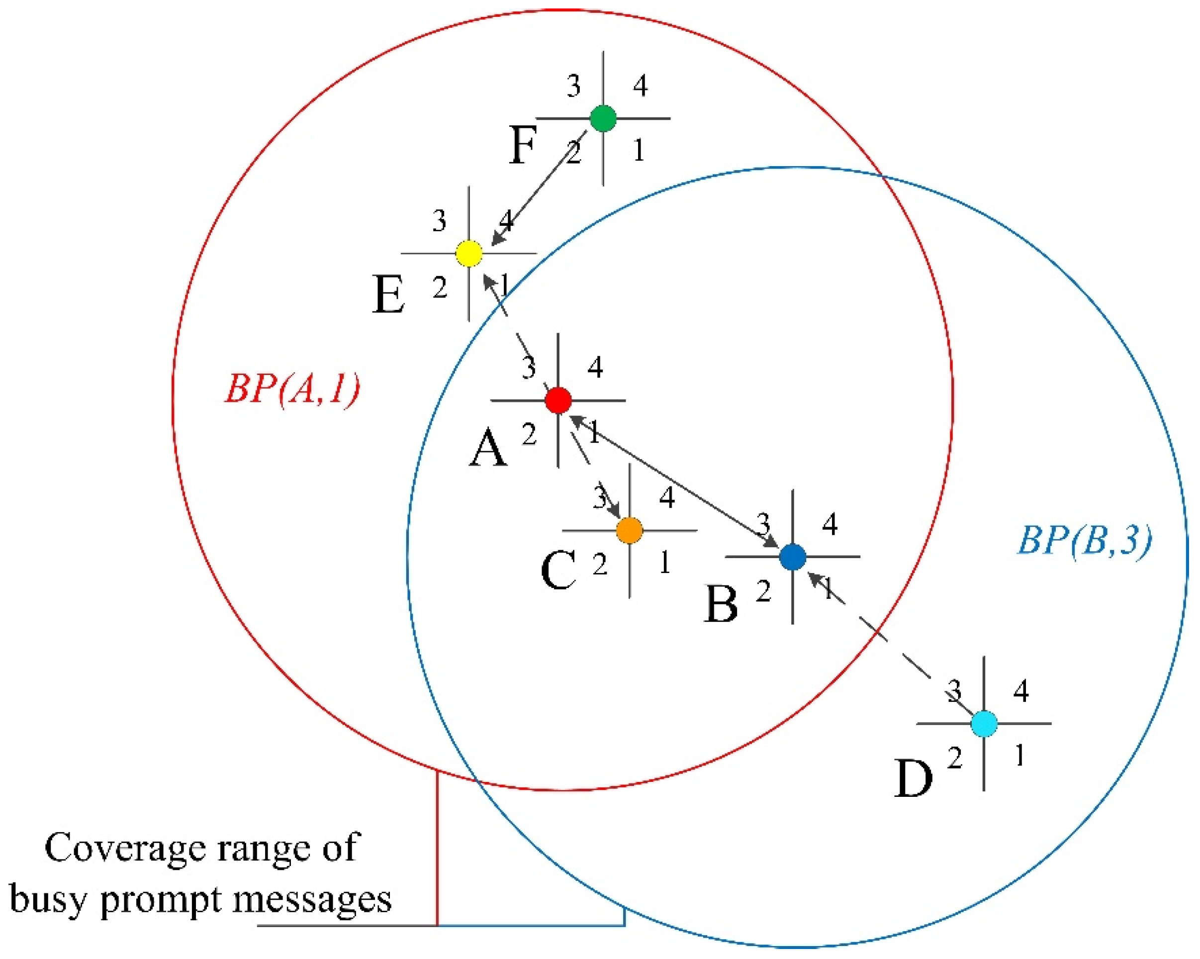
Figure 9 shows the working process of the DADC-MAC protocol. There are six nodes in the network: A, B, C, D, E, and F. As described above, each node is equipped with an omnidirectional antenna and a directional antenna. The directional antenna has four beams. The communication range of the omnidirectional antenna is same as that of the directional antenna in the direction mode. When Node A has DATA packet to be sent to Node B, it first judges the channel in the direction of Node B. If the channel in that direction is idle, Node A directionally sends a DRTS signal to Node B and then waits for Node B to send a DCTS signal back. After receiving the DRTS signal from Node A, Node B sends the DCTS signal back to Node A; it also sends channel busy prompt messages by the omnidirectional antenna with the content of B P ( B , 3 ) . Then, Node B waits for the DATA package sent by Node A. After Node A receives the DCTS signal, it sends the DATA package to Node B while sending channel busy prompt messages by the omnidirectional antenna with the content of B P ( A , 1 ) . After Node B successfully receives the DATA package, it sends an ACK signal back to Node A and stops sending the channel busy prompt messages. After Node A receives the ACK signal, it enters an idle state and stops sending the channel busy prompt messages. The data transmission process is complete.
Node D is the neighbor node within the communication range of Node B. When Node B communicates with Node A, Node D has data to be sent to Node B. The data transmission process is postponed to avoid collision when the channel busy prompt message sent by Node B is heard. Node C is the neighbor node within the communication range of Node A. Node C has data to be sent to Node E. Although data is not sent to Node A, as Node A is between Node C and Node E and on a straight line, the communication between Node C and Node E interferes in the communication between Node A and Node B. Thus, after Node C hears the channel busy prompt message send by Node A, it postpones the transmission to Node E so as to prevent interference with Node A. When Node A communicates with Node B, Node F has data to be sent to Node E. Although Node F receives the channel busy prompt message sent by Node A, the channel busy prompt message indicates that the communication between Node F and Node E must not interfere in the current data transmission. Therefore, Node A/Node B and Node E/Node F communicate at the same time to efficiently utilize network space.
The DADC-MAC protocol can also well resolve the hidden terminal and deafness problems described in Section 3. For the hidden terminal problem caused by the unheard DRTS/DCTS, as shown in Figure 2, although Node B hears the channel busy prompt message (though it does not receive the DCTS signal) sent by Node D, it knows that the channel in that direction is busy.
For the hidden terminal problem caused by the asymmetrical antenna gains, as shown in Figure 3, although Node A cannot receive DCTS signal sent by Node D, it can also receive the channel busy prompt message sent by Node C. It judges the channel in that direction as busy and postpones data transmission to Node B.
For the deafness problem, as shown in Figure 4, Node A has DATA package to be sent to Node B when Node B communicates with Node C. While hearing the channel in the direction of Node B, Node A receives the channel busy prompt message sent by Node B and thus knows Node B is communicating and postpones data transmission to it.

5. Performance Evaluation

We evaluated the performance of our MAC protocol by simulation in NS-3 [34,35]. In the simulation, we assumed the underwater acoustic channel to be an ideal channel without error. Each node is equipped with an omnidirectional antenna and a directional antenna, which have equal communication distance (1.8 km). The nodes are static. We assume all nodes have completed neighbor discovery and gained the position information of neighboring nodes before the simulation began. The MACA protocol and D-MAC protocol were used as references. The D-MAC protocol cannot operate smoothly without prior information of neighbor node positions, so we assume that the nodes in the D-MAC protocol networks have prior information of neighbor node positions in the simulation to ensure a fair performance comparison. The simulation process of all scenes were repeated 20 times and averaged. Simulation parameters are provided in Table 4.

5.1. Linear Networks

Firstly, two scenes are simulated in the linear networks. The first scene is shown in Figure 10. Four nodes in the networks present linear arrangement, and the distance among nodes is equal (1.2 km). The communication distance of the directional antenna and omnidirectional antenna is 1.8 km. The transmission rate of nodes is 1600 bps. Node 1 and Node 2 are an intercommunication pair (Link A): Node 2 is the sending node, and Node 1 is the receiving node. Similarly, Node 3 and Node 4 are an intercommunication pair (Link B) where Node 3 is the sending node, and Node 4 is the receiving node. The transmissions through link A from node 2 to node 1 and through link B from node 3 to node 4 are independent from each other. If the packet transmission through link A (or through link B) is successful, the transmission through the link will continue without considering the result of the transmission through link B (or link A). The duration of the simulation process is 1000 s. The total number of Data packages successfully received by Node 1 and Node 4 within the period is counted. The results are shown in Table 5.
The proposed protocol and D-MAC protocol showed far superior performance to that of the MACA protocol. This is because the application of directional antenna largely reduces the interference of the omnidirectional antenna across neighboring nodes. The difference in performance between the proposed protocol and D-MAC protocol is fairly small because the directions of two groups of communication processes in the scene are opposite to each other, and the probability of control frame collision in D-MAC is very small.
The second scene we simulated is shown in Figure 11. The nodes arrangement position and communication distance of node antenna are identical to Figure 10. Node 1 and Node 2 are an intercommunication pair (Link A): Node 1 is the sending node, and Node 2 is the receiving node. Similarly, Node 3 and Node 4 are an intercommunication pair (Link B): Node 3 is the sending node, and Node 4 is the receiving node. The transmissions through link A from node 1 to node 2 and through link B from node 3 to node 4 are independent from each other. If the packet transmission through link A (or through link B) is successful, the transmission through the link will continue without considering the result of the transmission through link B (or link A). The duration of the simulation process is 1000 s again and the total number of Data packages successfully received by Node 2 and Node 4 within the given period is counted. The results are shown in Table 6.
The performance of MACA protocol in this scene is very poor, because the process where Node 1 sends data to Node 2 greatly interferes in the communication between Node 3 and Node 4. By contrast, the proposed protocol and D-MAC protocol have effective collision prevention mechanisms. In the scene, the performance of D-MAC protocol differs markedly from the proposed protocol because the CTS signal sent by Node 2 still interferes in the communication between Node 3 and Node 4 in D-MAC. The proposed protocol prevents DATA package collision through sending channel busy prompt messages.

5.2. Grid Networks

We next simulated two scenes in grid networks. The network topology is shown in Figure 12. The interval between each line and each row is 1.2 km and the communication distance between omnidirectional antenna and directional antenna is 1.8 km. The node can directly communicate with its neighbor nodes on an adjacent line, adjacent row, and diagonal. As shown in Figure 12, Node 2 and Node 3 send DATA packages to Node 22 and Node 23 along the route of their respective rows. Node 6 and Node 11 send DATA packages to Node 10 and Node 15 along the current row. The duration of the simulation process is 1000 s. The total number of DATA packages successfully received by Node 10, Node 15, Node 22, and Node 23 within the period at different transmission rate is counted. The results are shown in Figure 13. The proposed protocol outperforms MACA and D-MAC because the omnidirectional communication mode of MACA results in severe interference, and the aligned path is problematic in D-MAC.
In the second grid network simulation scene, the node arrangement and communication distance of antennas were consistent with the first scene. Node 2, Node 3, Node 6, and Node 11 still send data to Node 22, Node 23, Node 10, and Node 15. As opposed to the previous scene wherein the fixed communication path was selected, the nodes in this scene choose paths at random. The duration of the simulation is still 1000 s and again, the total number of DATA packages successfully received by Node 22, Node 23, Node 10, and Node 15 within the period at different transmission rate is counted. The results are shown in Figure 14. The proposed protocol again outperforms the others. As shown in Figure 14, the performance of the proposed protocol and D-MAC protocol in this scene are superior to those in the previous scene. This is because random selection of path gives full play to the advantages of the directional antenna, i.e., the increases reuse of space.

5.3. Random Distribution Networks

We next validated the performance of the proposed protocol in a random distribution network. Fifty nodes in the scene were distributed in 5 km × 5 km, 10 km × 10 km area at random. The communication distance of the omnidirectional antenna and directional antenna is 1.2 km. Each node generates a DATA packet ready to be sent in every 20 s on an average (the arrivals follow a Poisson distribution with average λ = 0.05 packets per second). The sending node chooses the receiving node at random with equal probability. The distance between the sending node and receiving node was kept at least 3 km. The route of sending node and receiving node was calculated by the Dijkstra algorithm [36] and the simulation was run for a duration of 2000 s.
The total effective throughput capacity in the networks at different transmission rate is counted as shown in Figure 15. The throughput capacity of the proposed protocol is far superior to that of MACA and D-MAC on both sparse and dense networks because, compared to MACA, the use of a directional antenna reduces DATA package collision and increases space reuse. Compared to D-MAC, the proposed protocol divides the channel into a data transmission channel and busy prompt message channel to further reduce DATA package collision. DADC-MAC protocol could achieve higher throughput in relatively sparse networks. This is because when the network is denser, the number of neighboring nodes within a single beam of the sending node is greater. When the sending node sends a signal in a certain direction, the more neighboring nodes in the beam sector are affected.
End to end delay at different DATA packet length of DADC-MAC, D-MAC, and MACA is depicted in Figure 16. The transmission rate of nodes is 1600 bps. As shown in Figure 16, DADC-MAC can largely reduce the end-to-end delay of the networks in both sparse networks and dense networks than D-MAC and MACA. MACA has the highest end-to-end delay, because omnidirectional data transmission mode causes a large number of DATA packet collisions, and then causes node back-off and packet retransmission. As the length of the DATA packet increases, this disadvantage becomes more and more obvious. Although DADC-MAC and D-MAC both use directional data transmission, the end-to-end delay of DADC-MAC is much lower than that of D-MAC. It is because that DADC-MAC divides the underwater acoustic channel into a data transmission channel and a channel busy prompt message channel. The busy channel prompt message could help neighbor nodes obtain the channel status, arrange their own network behavior according to the channel status, avoid packet collision, and reduce packet retransmission.
In summary, we compared the proposed MAC protocol against the underwater protocol based on the omnidirectional antenna (MACA) and the protocol for TSNs with directional antenna (D-MAC). Simulations were run in both symmetrical network topology (linear networks and grid networks) and asymmetrical network topology (random distribution networks). The proposed protocol consistently completed more effective communications within the same amount of time and at higher network throughput than the other two protocols.

6. Conclusions and Future Work

This paper proposed a dual channel MAC protocol for underwater acoustic sensor networks based on directional antenna (DADC-MAC). In the DADC-MAC protocol, the node is equipped with a directional antenna, which comes with efficient use of space, and low interference in neighboring nodes. The channel is divided into a data transmission channel and busy prompt message channel able to inform the on-going communication of neighbor nodes to prevent DATA packages collision. The DADC-MAC protocol also adopts a neighbor discovery mechanism and directional network allocation vector to resolve the hidden terminal and deafness problems caused by the directional antenna. A series of simulations were conducted to find that compared to other underwater protocol based on the omnidirectional antenna, or protocol for TSNs with the directional antenna, the DADC-MAC protocol completes more effective communications within the same time and yields higher network throughput, lower end-to-end delay. To this effect, it is very well suited to UASNs.
As future work, due to a good cross-layer design, usually could significantly improve the performance of UASNs, it is important for us to research a cross-layer design of MAC protocol and routing protocol based on the results of this paper. Moreover, we need to consider possible problems in real implementation. For example, in this paper, the switch time between directional mode and omnidirectional mode of the directional antenna was ignored, it cannot be ignored in real-world scenarios; and when the node is placed in the water, it will randomly rotate due to factors such as water flow.

Author Contributions

Conceptualization, J.Y., G.Q. and Q.H.; investigation, J.Z. and G.D.; methodology, J.Y. and G.Q.; software, J.Y. and J.Z.; supervision, G.Q. and Q.H.; validation, J.Y., J.Z. and G.D.; writing—original draft, J.Y., J.Z. and G.D.; writing—review and editing, J.Y. and J.Z. All authors have read and agreed to the published version of the manuscript.

Funding

This work was supported by the National Key Research and Development Program of China under Grant No. 2018YFC0308500 and 2017YFC0305702, the National Natural Science Foundation of China under Grant No. 61771152, 11774074 and 11974090, the Stable Supporting Fund of Acoustic Science and Technology Laboratory under Grant No. JCKYS2020604SSJS015, the Science and Technology on Sonar Laboratory under Grant No. 6142109180101.

Conflicts of Interest

The authors declare no conflict of interest.

References

  1. Qiao, G.; Zhao, Y.J.; Liu, S.Z.; Ahmed, N. Doppler scale estimation for varied speed mobile frequency-hopped binary frequency-shift keying underwater acoustic communication. J. Acoust. Soc. Am. 2019, 146, 998–1004. [Google Scholar] [CrossRef]
  2. Che, X.; Wells, I.; Dickers, G.; Kear, P. TDMA frame design for a prototype underwater RF communication network. Ad Hoc Netw. 2012, 10, 317–327. [Google Scholar] [CrossRef] [Green Version]
  3. Sahu, S.K.; Shanmugam, P. A theoretical study on the impact of particle scattering on the channel characteristics of underwater optical communication system. Opt. Commun. 2018, 408, 3–14. [Google Scholar] [CrossRef]
  4. Luo, J.; Fan, L.; Wu, S.; Yan, X. Research on Localization Algorithms Based on Acoustic Communication for Underwater Sensor Networks. Sensors 2018, 18, 67. [Google Scholar] [CrossRef] [Green Version]
  5. He, C.; Xi, R.; Wang, H.; Jing, L.; Shi, W.; Zhang, Q. Single Carrier with Frequency Domain Equalization for Synthetic Aperture Underwater Acoustic Communications. Sensors 2017, 17, 1584. [Google Scholar] [CrossRef] [Green Version]
  6. Li, N.; Martinez, J.; Chaus, J.M.; Eckert, M. A Survey on Underwater Acoustic Sensor Network Routing Protocols. Sensors 2016, 16, 414. [Google Scholar] [CrossRef] [PubMed] [Green Version]
  7. Hanson, F.; Radic, S. High bandwidth underwater optical communication. Appl. Opt. 2008, 47, 277–283. [Google Scholar] [CrossRef]
  8. Santos, R.; Orozco, J.; Ochoa, S.F.; Meseguer, R.; Eggly, G.; Pistonesi, M.F. A MAC Protocol to Support Monitoring of Underwater Spaces. Sensors 2016, 16, 984. [Google Scholar] [CrossRef] [Green Version]
  9. Ahmed, M.; Salleh, M.; Channa, M.I. Routing protocols for underwater wireless sensor networks based on data forwarding: A review. Telecommun. Syst. 2017, 65, 139–153. [Google Scholar] [CrossRef]
  10. Sendra, S.; Lloret, J.; Jimenez, J.M.; Ghafoor, K.Z. Underwater Ad Hoc Wireless Communication for Video Delivery. Wirel. Pers. Commun. 2017, 96, 5123–5144. [Google Scholar] [CrossRef]
  11. Maki, T.; Matsuda, T.; Sakamaki, T.; Ura, T.; Kojima, J. Navigation Method for Underwater Vehicles Based on Mutual Acoustical Positioning With a Single Seafloor Station. IEEE J. Ocean. Eng. 2013, 38, 167–177. [Google Scholar] [CrossRef]
  12. Stojanovic, M.; Preisig, J. Underwater Acoustic Communication Channels: Propagation Models and Statistical Characterization. IEEE Commun. Mag. 2009, 47, 84–89. [Google Scholar] [CrossRef]
  13. Chitre, M.; Shahabudeen, S.; Stojanovic, M. Underwater acoustic communications and networking: Recent advances and future challenges. Mar. Technol. Soc. J. 2008, 42, 103–116. [Google Scholar] [CrossRef]
  14. Zikria, Y.; Afzal, M.K.; Kim, S.W. Internet of Multimedia Things (IoMT): Opportunities, Challenges and Solutions. Sensors 2020, 20, 2334. [Google Scholar] [CrossRef]
  15. Noh, Y.; Lee, U.; Han, S.; Wang, P.; Torres, D.; Kim, J.; Gerla, M. DOTS: A Propagation Delay-Aware Opportunistic MAC Protocol for Mobile Underwater Networks. IEEE Trans. Mob. Comput. 2014, 13, 766–782. [Google Scholar] [CrossRef]
  16. Zhu, Y.B.; Peng, Z.; Cui, J.H.; Chen, H.F. Toward Practical MAC Design for Underwater Acoustic Networks. IEEE Trans. Mob. Comput. 2015, 14, 872–886. [Google Scholar] [CrossRef]
  17. Su, Y.S.; Zhu, Y.B.; Mo, H.N.; Cui, J.H.; Jin, Z.G. A joint power control and rate adaptation MAC protocol for underwater sensor networks. Ad Hoc Netw. 2015, 26, 36–49. [Google Scholar] [CrossRef]
  18. Ramanathan, R.; Redi, J.; Santivanez, C.; Wiggins, D.; Polit, S. Ad hoc networking with directional antennas: A complete system solution. IEEE J. Sel. Areas Commun. 2005, 23, 496–506. [Google Scholar] [CrossRef]
  19. Dai, H.N.; Ng, K.W.; Li, M.L.; Wu, M.Y. An overview of using directional antennas in wireless networks. Int. J. Commun. Syst. 2013, 26, 413–448. [Google Scholar] [CrossRef]
  20. Rhee, I.; Warrier, A.; Aia, M.; Min, J.; Sichitiu, M.L. Z-MAC: A hybrid MAC for wireless sensor networks. IEEE/ACM Trans. Netw. 2008, 16, 511–524. [Google Scholar] [CrossRef]
  21. Otal, B.; Alonso, L.; Verikoukis, C. Highly Reliable Energy-Saving MAC for Wireless Body Sensor Networks in Healthcare Systems. IEEE J. Sel. Areas Commun. 2009, 27, 553–565. [Google Scholar] [CrossRef]
  22. Vieira, L.F.M.; Kong, J.; Lee, U.; Gerla, M. Analysis of aloha protocols for underwater acoustic sensor networks. In Proceedings of the ACM Wuwnet’06, Los Angeles, CA, USA, 25 September 2006. [Google Scholar]
  23. Zhou, Y.; Chen, K.; He, J.; Guan, H. Enhanced slotted aloha protocols for underwater sensor networks with large propagation delay. In Proceedings of the First International Conference on Embedded Networked Sensor Systems, Yokohama, Japan, 15–18 May 2011; pp. 1–5. [Google Scholar]
  24. Petrioli, C.; Petroccia, R.; Stojanovic, M. A comparative performance evaluation of MAC protocols for underwater sensor networks. In Proceedings of the Oceans 2008, Quebec City, QC, Canada, 15–18 September 2008; pp. 1–10. [Google Scholar]
  25. Dou, F.; Jin, Z.; Su, Y.; Liu, J. WSF-MAC: A weight-based spatially fair MAC protocol for underwater sensor networks. In Proceedings of the 2012 2nd International Conference on Consumer Electronics, Communications and Networks, Yichang, China, 21–23 April 2012; pp. 3708–3711. [Google Scholar]
  26. Yang, M.; Gao, M.; Foh, C.; Cai, J.; Chatzimisios, P. DC-MAC: A Data-centric Multi-hop MAC protocol for Underwater Acoustic Sensor Networks. In Proceedings of the Computers and Communications (ISCC), Corfu, Greece, 28 June–1 July 2011; pp. 491–496. [Google Scholar]
  27. Tan, H.X.; Seah, W.K.G. Distributed CDMA-based MAC protocol for underwater sensor networks. In Proceedings of the IEEE 32nd Conference Local Computer Networks, Dublin, Ireland, 15–18 October 2007; pp. 26–36. [Google Scholar]
  28. Pompili, D.; Melodia, T.; Akyildiz, I.F. A CDMA-Based Medium Access Control for Underwater Acoustic Sensor Networks. IEEE Trans. Wirel. Commun. 2009, 8, 1899–1909. [Google Scholar] [CrossRef]
  29. Pompili, D.; Akyildiz, I.F. Overview of Networking-Protocols for Underwater Wireless Communications. IEEE Commun. Mag. 2009, 47, 97–102. [Google Scholar] [CrossRef]
  30. Kredo, K.B., II; Mohapatra, P. A hybrid medium access control protocol for underwater wireless networks. In Proceedings of the Annual International Conference on Mobile Computing and Networking, Montréal, QC, Canada, 14 September 2007; pp. 33–40. [Google Scholar]
  31. Diamant, R.; Lampe, L. Spatial Reuse Time-Division Multiple Access for Broadcast Ad Hoc Underwater Acoustic Communication Networks. IEEE J. Ocean. Eng. 2011, 36, 172–185. [Google Scholar] [CrossRef]
  32. Diamant, R.; Lampe, L. A hybrid spatial reuse MAC protocol for ad-hoc underwater acoustic communication networks. In Proceedings of the Communications Workshops, Capetown, South Africa, 23–27 May 2010; pp. 1–5. [Google Scholar]
  33. Butler, A.L.; Butler, J.L.; Dalton, W.L.; Rice, J.A. Multimode directional telesonar transducer. In Proceedings of the OCEANS 2000 MTS/IEEE - WHERE MARINE SCIENCE AND TECHNOLOGY MEET, Providence, RI, USA, 11–14 September 2000; pp. 1289–1292. [Google Scholar]
  34. Van den Abeele, F.; Haxhibeqiri, J.; Moerman, I.; Hoebeke, J. Scalability Analysis of Large-Scale LoRaWAN Networks in ns-3. IEEE Internet Things J. 2017, 4, 2186–2198. [Google Scholar] [CrossRef] [Green Version]
  35. Rana, M.K.; Sardar, B.; Mandal, S.; Saha, D. Implementation and performance evaluation of a mobile IPv6 (MIPv6) simulation model for ns-3. Simul. Model. Pract. Theory 2017, 72, 1–22. [Google Scholar] [CrossRef]
  36. Dijkstra, E.W. A Note on Two Problems in Connexion with Graphs. Numer. Math. 1959, 1, 269–271. [Google Scholar] [CrossRef] [Green Version]
Figure 1. Classification of medium access control (MAC) protocols for underwater acoustic sensor networks (UASNs).
Symmetry 12 00878 g001
Figure 2. Hidden terminal problem caused by unheard DRTS/DCTS.
Symmetry 12 00878 g002
Figure 3. Hidden terminal problem caused by asymmetrical antenna gains.
Symmetry 12 00878 g003
Figure 4. Deafness problem.
Symmetry 12 00878 g004
Figure 5. Directional antenna
Symmetry 12 00878 g005
Figure 6. An example of neighbor discovery and directional network allocation vector.
Symmetry 12 00878 g006
Figure 7. Timing diagram of channel busy prompt message
Symmetry 12 00878 g007
Figure 8. The flow chart of the directional antenna (DADC-MAC) protocol. (a) The transmitting terminal; (b) The receiving terminal.
Symmetry 12 00878 g008
Figure 9. An example of the DADC-MAC protocol.
Symmetry 12 00878 g009
Figure 10. Linear networks scene 1.
Symmetry 12 00878 g010
Figure 11. Linear networks scene 2.
Symmetry 12 00878 g011
Figure 12. Grid networks.
Symmetry 12 00878 g012
Figure 13. Total number of DATA packages successfully received by Node 10, Node 15, Node 22, and Node 23 (Grid Networks scene 1).
Symmetry 12 00878 g013
Figure 14. Total number of DATA packages successfully received by Node 10, Node 15, Node 22, and Node 23 (Grid Networks scene 2).
Symmetry 12 00878 g014
Figure 15. Networks throughput at different transmission rate.
Symmetry 12 00878 g015
Figure 16. End-to-end delay at different DATA packet length.
Symmetry 12 00878 g016
Table 1. Comparison of MAC protocols mentioned in related work.
CategoryProtocolAimProposed SolutionPros and Cons
CONTENTION-BASEDRandom AccessISA-ALOHAMinimize the adverse impact of propagation delayAdjust time slot values according to time delay estimationsStrong robustness; high requirements for time delay estimation
PDAPMaximizing the bandwidth utilizationKeep track of the neighboring transmissionsIncreased channel utilization; cannot reliably acquire the channel
HandshakingWSF-MACOvercome the issue of spatial unfairnessSend the underwater reply packet for a silence duration timeAchieved a better performance in terms of the spatial fairness; different competition thresholds cause different fairness
DC-MACEnhance the performance on throughput and average end-to-end delayMulti-channel and dynamic collision-free polling strategyEliminated the hidden terminal problem and improved network performance; not suitable to multiple sink nodes
HYBRIDPLANUse in half-duplex underwater acoustic sensor networksUtilize the CDMA as the underlying medium access techniqueMinimize multipath and Doppler effects; suffer from the missing receiver problem
UW-MACHigh network throughput, low energy consumptionTransmitter adjusts pseudo-random sequences length and signal powerReduce multiple access interference; require all nodes know other nodes’ multiple access interference
H-MACYield the benefits from contention-free and random access protocolsDivide a time frame into two time slotsLittle power consumption; not be optimal for dense and heavily loaded network
HSR-TDMAImprove network throughputSpatial reuseLess sensitive to topology changes; strict synchronization among is required
Table 2. Acronyms and notations used in this paper.
Acronym and NotationDescription
UASNsUnderwater acoustic sensor networks
TSNsTerrestrial sensor networks
RFRadio frequency
MACMedium access control
RTSReady to send
CTSClear to send
ACKAcknowledgement
DRTSDirectional ready to send
DCTSDirectional clear to send
NLTNeighbor information table
GOAntenna gain of the omnidirectional mode
GDAntenna gain of the directional mode
Table 3. Neighbor information table (NLT) and directional network allocation vector of Node C.
Beam NumberNeighbor Nodes IDAvailableDuration
1---
2---
3A, BNO-
4DYES15 s
Table 4. Simulation parameters.
ParameterValue
Speed of sound1500 m/s
Directional antenna beams number4
Maximum DATA package retransmission number2
Channel busy prompt message size16 bits
Control packet (i.e., DRTS, DCTS, ACK) size128 bits
DATA packet size2400 bits
Transmission rate1600 bps
Center frequency11 kHz
Bandwidth6 kHz
Table 5. Simulation results of Linear networks scene 1.
Node NumberMACAD-MACDADC-MAC
161.45120.50126.50
462.7120.55119.05
Total124.15241.05245.55
Table 6. Simulation results of Linear networks scene 2.
Node NumberMACAD-MACDADC-MAC
21.5568.40115.25
4118.1091.00117.80
Total119.65159.40233.05

