RETRACTED: Hybrid Thermal-Chemical Enhanced Oil Recovery Methods; An Experimental Study for Tight Reservoirs


Abstract
:1. Introduction
2. Materials and Methods
2.1. Materials
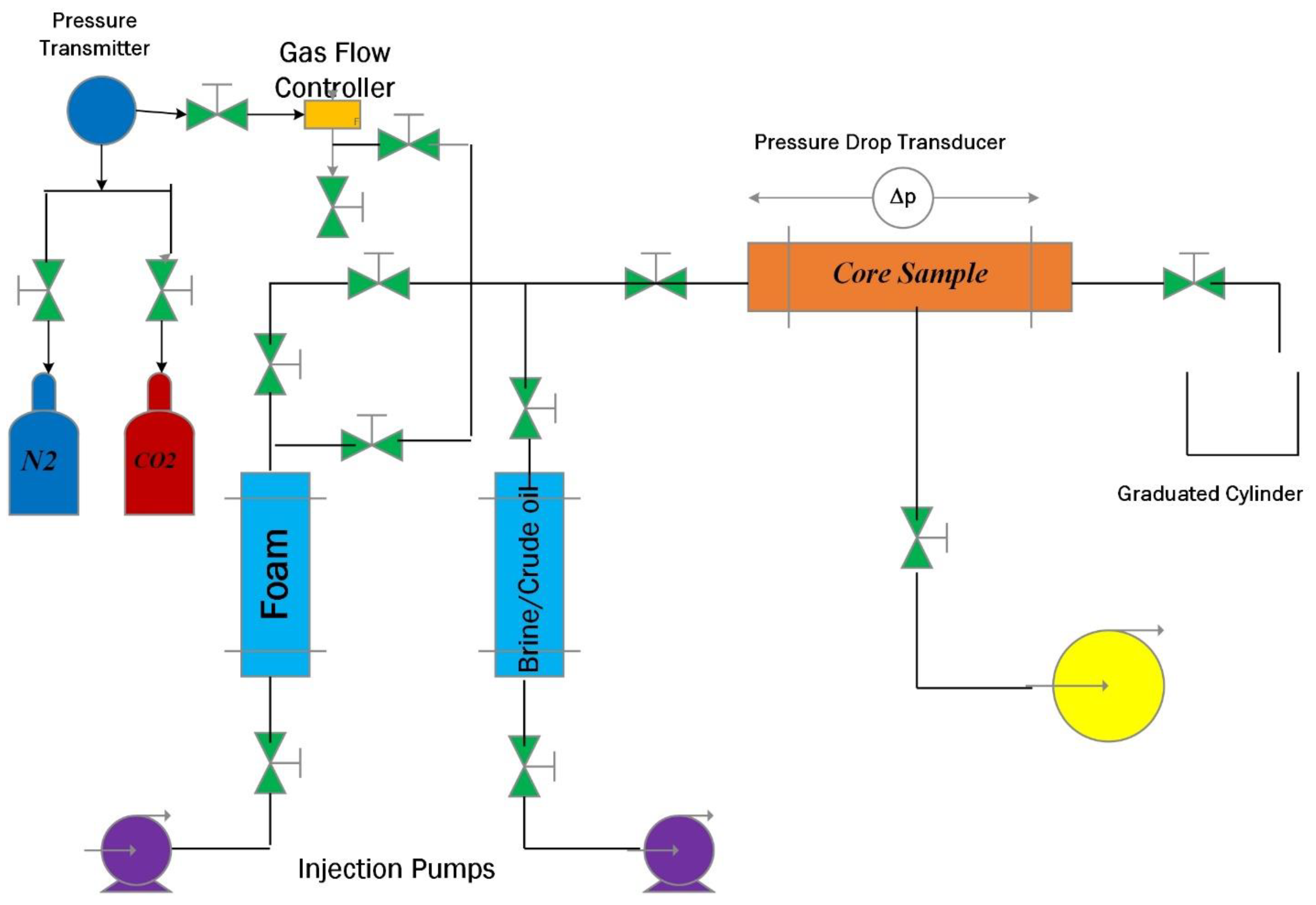
2.2. Core Flooding
3. Results and Discussion
3.1. Mobility Ratio
3.2. Resistance Factor
3.3. Pressure Drop
3.4. Recovery Factor
3.5. Brine Component
4. Conclusions
Author Contributions
Funding
Acknowledgments
Conflicts of Interest
References
- Tang, J.; Wu, K.; Zeng, B.; Huang, H.; Hu, X.; Guo, X.; Zuo, L. Investigate effects of weak bedding interfaces on fracture geometry in unconventional reservoirs. J. Pet. Sci. Eng. 2018, 165, 992–1009. [Google Scholar] [CrossRef]
- Omran, M.; Berg, C.F. Applying new rock typing methods, and modelling for conventional & unconventional reservoirs. In Proceedings of the International Petroleum Technology Conference, Dhahran, Saudi Arabia, 13–15 January 2020. [Google Scholar]
- Nikolaev, M.; Kazak, A. Liquid saturation evaluation in organic-rich unconventional reservoirs: A comprehensive review. Earth Sci. Rev. 2019. [Google Scholar] [CrossRef]
- Zhang, Y.; Lashgari, H.R.; Di, Y.; Sepehrnoori, K. Capillary pressure effect on phase behavior of CO2/hydrocarbons in unconventional reservoirs. Fuel 2017, 197, 575–582. [Google Scholar] [CrossRef]
- Hoffman, B. Enhanced oil recovery in unconventional reservoirs. In Proceedings of the 81st EAGE Conference and Exhibition 2019, European Association of Geoscientists & Engineers, Houten, The Netherlands, 3–6 June 2019; pp. 1–5. [Google Scholar]
- Uzun, I.; Kurtoglu, B.; Kazemi, H. Multiphase rate-transient analysis in unconventional reservoirs: Theory and application. SPE Reserv. Eval. Eng. 2016, 19, 553–566. [Google Scholar] [CrossRef]
- Todd, H.B.; Evans, J.G. Improved Oil Recovery IOR Pilot Projects in the Bakken Formation; SPE Low Perm Symposium, Society of Petroleum Engineers: Richardson, TX, USA, 2016. [Google Scholar]
- Pillai, V.; Kanicky, J.R.; Shah, D.O. Applications of microemulsions in enhanced oil recovery. In Handbook of Microemulsion Science and Technology; Routledge: New York, NY, USA, 2018; pp. 743–754. [Google Scholar]
- Jin, L.; Hawthorne, S.; Sorensen, J.; Pekot, L.; Kurz, B.; Smith, S.; Heebink, L.; Herdegen, V.; Bosshart, N.; Torres, J. Advancing CO2 enhanced oil recovery and storage in unconventional oil play—Experimental studies on Bakken shales. Appl. Energy 2017, 208, 171–183. [Google Scholar] [CrossRef]
- Chávez-Miyauchi, T.S.E.; Firoozabadi, A.; Fuller, G.G. Nonmonotonic elasticity of the crude oil—Brine interface in relation to improved oil recovery. Langmuir 2016, 32, 2192–2198. [Google Scholar] [CrossRef]
- Liu, Y.; Ren, S.; Zhang, L.; Wang, S.; Xu, G. Enhanced nitrogen foams injection for improved oil recovery: From laboratory to field implementation in viscous oil reservoirs offshore Bohai Bay China. Int. J. Oil Gas Coal Technol. 2019, 21, 463–481. [Google Scholar] [CrossRef]
- Seyyedi, M.; Mahzari, P.; Sohrabi, M. An integrated study of the dominant mechanism leading to improved oil recovery by carbonated water injection. J. Ind. Eng. Chem. 2017, 45, 22–32. [Google Scholar] [CrossRef]
- Kazemi Nia Korrani, A.; Sepehrnoori, K.; Delshad, M. A mechanistic integrated geochemical and chemical-flooding tool for alkaline/surfactant/polymer floods. SPE J. 2016, 21, 32–54. [Google Scholar] [CrossRef]
- Lake, L.W.; Johns, R.; Rossen, W.R.; Pope, G.A. Fundamentals of enhanced oil recovery. In Enhanced Oil Recovery; Society of Petroleum Engineers: Richardson, TX, USA, 2014. [Google Scholar]
- Davarpanah, A. A feasible visual investigation for associative foam >⧹polymer injectivity performances in the oil recovery enhancement. Eur. Polym. J. 2018, 105, 405–411. [Google Scholar] [CrossRef]
- Ashraf, S.; Abdullah, S.; Aslam, M. Symmetric sum based aggregation operators for spherical fuzzy information: Application in multi-attribute group decision making problem. J. Intell. Fuzzy Syst. 2020. [Google Scholar] [CrossRef]
- Wang, H.; Li, J.; Wang, Z.; Wang, D.; Zhan, H. Experimental investigation of the mechanism of foaming agent concentration affecting foam stability. J. Surfactants Deterg. 2017, 20, 1443–1451. [Google Scholar] [CrossRef]
- Bai, C.; Franchin, G.; Elsayed, H.; Zaggia, A.; Conte, L.; Li, H.; Colombo, P. High-porosity geopolymer foams with tailored porosity for thermal insulation and wastewater treatment. J. Mater. Res. 2017, 32, 3251–3259. [Google Scholar] [CrossRef]
- Davarpanah, A.; Mirshekari, B. Numerical simulation and laboratory evaluation of alkali–surfactant–polymer and foam flooding. Int. J. Environ. Sci. Technol. 2019, 17, 1123–1136. [Google Scholar] [CrossRef]
- Wilson, A.J. Experimental techniques for the characterization of foams. In Foams; Routledge: New York, NY, USA, 2017; pp. 243–274. [Google Scholar]
- Davarpanah, A.; Shirmohammadi, R.; Mirshekari, B. Experimental evaluation of polymer-enhanced foam transportation on the foam stabilization in the porous media. Int. J. Environ. Sci. Technol. 2019, 16, 8107–8116. [Google Scholar] [CrossRef]
- Fei, Y.; Pokalai, K.; Johnson, R., Jr.; Gonzalez, M.; Haghighi, M. Experimental and simulation study of foam stability and the effects on hydraulic fracture proppant placement. J. Nat. Gas Sci. Eng. 2017, 46, 544–554. [Google Scholar] [CrossRef]
- Yu, W.; Lashgari, H.R.; Wu, K.; Sepehrnoori, K. CO2 injection for enhanced oil recovery in Bakken tight oil reservoirs. Fuel 2015, 159, 354–363. [Google Scholar] [CrossRef]
- Zuloaga-Molero, P.; Yu, W.; Xu, Y.; Sepehrnoori, K.; Li, B. Simulation study of CO2-EOR in tight oil reservoirs with complex fracture geometries. Sci. Rep. 2016, 6, 33445. [Google Scholar] [CrossRef]
- Liu, P.; Zhang, X.; Wu, Y.; Li, X. Enhanced oil recovery by air-foam flooding system in tight oil reservoirs: Study on the profile-controlling mechanisms. J. Pet. Sci. Eng. 2017, 150, 208–216. [Google Scholar] [CrossRef]
- Alharthy, N.; Teklu, T.W.; Kazemi, H.; Graves, R.M.; Hawthorne, S.B.; Braunberger, J.; Kurtoglu, B. Enhanced oil recovery in liquid-rich shale reservoirs: Laboratory to field. SPE Reserv. Eval. Eng. 2018, 21, 137–159. [Google Scholar] [CrossRef]
- Davarpanah, A.; Mirshekari, B. A simulation study to control the oil production rate of oil-rim reservoir under different injectivity scenarios. Energy Rep. 2018, 4, 664–670. [Google Scholar] [CrossRef]


| Brine Type | TDS (mg/L) | pH (25 °C) | pH (85 °C) | Density (25 °C) g/cm3 | Density (85 °C) g/cm3 |
|---|---|---|---|---|---|
| CaCl2 | 500−6000 | 6.7−7.1 | 6.5−7 | 1.0002−1.003 | 0.98−0.985 |
| KCl | 500−6000 | 6.21−6.68 | 6.12−6.53 | 1−1.0025 | 0.975−0.98 |
| Formation Brine | 130000 | 7.2 | 7.05 | 1.025 | 0.98 |
© 2020 by the authors. Licensee MDPI, Basel, Switzerland. This article is an open access article distributed under the terms and conditions of the Creative Commons Attribution (CC BY) license (http://creativecommons.org/licenses/by/4.0/).
Share and Cite
Hu, X.; Li, M.; Peng, C.; Davarpanah, A. RETRACTED: Hybrid Thermal-Chemical Enhanced Oil Recovery Methods; An Experimental Study for Tight Reservoirs. Symmetry 2020, 12, 947. https://doi.org/10.3390/sym12060947
Hu X, Li M, Peng C, Davarpanah A. RETRACTED: Hybrid Thermal-Chemical Enhanced Oil Recovery Methods; An Experimental Study for Tight Reservoirs. Symmetry. 2020; 12(6):947. https://doi.org/10.3390/sym12060947
Chicago/Turabian StyleHu, Xiaoyong, Moutao Li, Chenggen Peng, and Afshin Davarpanah. 2020. "RETRACTED: Hybrid Thermal-Chemical Enhanced Oil Recovery Methods; An Experimental Study for Tight Reservoirs" Symmetry 12, no. 6: 947. https://doi.org/10.3390/sym12060947
APA StyleHu, X., Li, M., Peng, C., & Davarpanah, A. (2020). RETRACTED: Hybrid Thermal-Chemical Enhanced Oil Recovery Methods; An Experimental Study for Tight Reservoirs. Symmetry, 12(6), 947. https://doi.org/10.3390/sym12060947