Article

Heat Transfer Enhancement in a Novel Annular Tube with Outer Straight and Inner Twisted Oval Tubes

1
School of Mechanical Engineering, Key Laboratory of Railway Vehicle Thermal Engineering of MOE, Lanzhou Jiaotong University, Lanzhou 730070, China
2
Department of Aeronautics and Astronautics, Tokyo Metropolitan University, Hino, Tokyo 191-0065, Japan
*
Author to whom correspondence should be addressed.
Symmetry 2020, 12(8), 1213; https://doi.org/10.3390/sym12081213
Submission received: 25 June 2020 / Revised: 20 July 2020 / Accepted: 21 July 2020 / Published: 23 July 2020
(This article belongs to the Special Issue Symmetry in Fluid Flow)

Abstract

:
The thermal-hydraulic performance in a novel annular tube formed by outer straight and inner twisted oval tubes is numerically investigated. An annular tube formed by two straight oval tubes is also studied for comparison. Inner twisted oval tubes with different aspect ratios and twist ratios are studied. The heat transfer is well improved by the symmetrical secondary flow in the annulus. The Nusselt number generally increases when the inner oval tube becomes flatter and the twists stronger in the studied range of geometrical parameters. The largest Nusselt number Nu of the inner twisted tube increases by 116% while the friction factor f increases by only 46% compared with that of the inner straight tube, and the largest value of the thermal performance factor (JF) can be up to 1.9. Correlations of the Nusselt number and friction factor are proposed for laminar and turbulent flows, and the deviations of the correlations are within ±5% and ±4% for Nu and f, respectively.

1. Introduction

The double-pipe heat exchanger (DPHE) is widely applied in numerous energy fields due to its simplicity, convenient cleaning and wide range of applications [1]. Improving the performance of the DPHE is of great significance for energy conservation. Active and passive techniques are the two main methods for heat transfer enhancement. The active techniques, such as using ultrasonic vibration [2] and magnetic fields [3,4,5], need external power. The passive techniques, such as tube inserts [6,7], turbulators [8], vortex generators [9,10,11] and special shaped tubes [12,13,14], can induce strong secondary flow, which has been proven to be beneficial to heat transfer [15,16,17,18,19]. These passive techniques with lower operating costs and higher stability and reliability are the main applied techniques in DPHE.
Tube inserts can effectively improve the heat transfer inside the tubes. Zhang et al. [6] researched a DPHE with a self-rotating twisted tape and reported that the Nu and f increase as the perforation ratio increases for the self-rotating twisted tape. Mashoofi et al. [7] experimentally reported that the axially perforated twisted tape has better heat transfer performance than the simple twisted tape, and the largest enhancement factor of 1.07 is obtained when the perforation diameter is 5 mm. Esmaeilzadeh et al. [20] experimentally revealed that the twisted tape inserts can markedly improve the convective heat transfer of the circular tube. Man et al. [21] experimentally studied the heat transfer performance of a twisted tape insert and found that both Nu and f increased significantly.
Sheikholeslami and Ganji [8] showed that the perforated turbulators with optimum geometry can obtain a value of the thermal performance factor (JF) up to 1.59 at Reynold’s number (Re) = 6000. Except for the tube inserts, there are many types of turbulator for enhancing the heat transfer performance. Pourahmad and Pesteei [22] mounted galvanized plate turbulators into the inner tube to determine the influence of the angle of the turbulator on the performance of a DPHE and reported that the turbulator increases the effectiveness by 26–71%, and the best turbulator angle is 45°. Zhang et al. [23] experimentally revealed that rotor-assembled strands can significantly improve the Nu by 71.5% to 123.1%, while the f increases by only 37.4% to 74.8% as compared with that of the smooth tube.
The thermal performance of an annular tube with an inner twisted square tube has been experimentally and numerically investigated by Bhadouriya et al. [24]. The results showed that the Nu increases as Re and Pr increase, and decreases as the twist ratio increases. Bashtani and Esfahani [25] numerically evaluated the thermal performance of three corrugated tubes with various wave amplitudes. The results showed that the highest Nu is 1.75 times larger than that for the simple tube at identical Re. Zambaux et al. [26] numerically investigated the heat transfer performance of the annular tube, of which both the inner and outer tube walls are formed by successive alternating wall deformations. They found that the value of JF can be up to 1.43 for all the investigated cases when the longitudinal phase-shifting of the tube is equal to 1/8. Wang et al. [27] numerically studied a DPHE by employing an outward helical corrugated tube as the inner tube. They found that secondary and swirling flows are generated on the sides of the tube and shell, and the optimum geometric parameter is obtained at the shell diameter of 38 mm. A numerical investigation by Gorman et al. [28] revealed that the heat transfer rate and the pressure drop of the helically corrugated DPHE were, respectively, three times and two times those of the simple smooth-walled DPHE. Qi et al. [29] experimentally revealed that a DPHE with a corrugated tube has better overall performance than a DPHE with a smooth tube.
Although a large amount of literature has reported the study of various geometric parameters of the DPHEs, the outer tubes are mainly circular tubes. No paper has focused on outer straight and inner twisted oval tubes in a DPHE in the open literature. A novel annular tube for a DPHE with outer straight and inner twisted oval tubes is proposed in this paper. The influences of the aspect and twist ratios of the inner tube on the flow characteristics and heat transfer performance in the annular tube are numerically studied. The thermal-hydraulic performance of the annular tube is markedly improved by an inner twisted oval tube. The results have significance for the design of DPHEs for the purpose of high thermal performance.

2. Physical Model and Numerical Method

Figure 1 shows a schematic view of the studied annular tube. The tube length (L) is 1500 mm. The long-axis (a0) and short-axis (b0) of the outer straight oval tube are 41 mm and 30.75 mm, respectively. The inner oval tube has a constant long-axis (ai) of 24 mm, and the studied three short-axes (bi) are 9.6 mm, 12 mm, and 14.4 mm. The twist pitches (P) considered are 240 mm, 360 mm, and 480 mm. The twist ratio (s) and the aspect ratio (e) of the inner oval tube are determined as s = P/ai and e = bi/ai, respectively. The dimensionless length is defined as X = x/P. In this study, the twist ratios are equal to s = 10, 15, 20 and the aspect ratios are equal to e = 0.4, 0.5, 0.6.
There are some assumptions in the present study, such as the air in the annulus being incompressible with constant property parameters and the Prandtl number of air being 0.7. The fluid flow is three-dimensional under steady state. The radiation, body force, gravity, and viscous dissipation are not considered. Re varies from 1000 to 15,000, including laminar and turbulent states. The experimental data reported by Bhadouriya et al. [24] indicated that the flow is considered to be laminar at Re ≤ 3000 and turbulent at Re > 3000. The continuity, momentum, and energy equations are:
x i ( ρ u i ) = 0
x i ( ρ u i u j ) = p x j + x i ( ( μ + μ t ) u j x i )
x i ( ρ C p u i T ) = x i ( ( λ + λ t ) T x i )
where μt and λt are the turbulent dynamic viscosity and thermal conductivity, respectively. μt and λt are equal to zero for laminar flow.
The Re-normalization Group (RNG) kε model is applied for the turbulent flow with the near-wall treatment approach of enhanced wall treatment. k and ε are given as below [30,31,32]:
x i ( ρ k u i ) = x i ( ( μ + μ t ) k x i ) + G k ρ ε
x i ( ρ ε u i ) = x i ( ( μ + μ t ) ε x i ) + C 1 ε ε k G k C 2 ε ρ ε 2 k
where Gk is the production of turbulent kinetic energy caused by the mean velocity gradients. The turbulent dynamic viscosity μt and turbulent thermal conductivity λt are given by μt = ρCμk2/ε and λt = Cpμt/Prt. The value of the turbulent Prandtl number Prt is set as 0.85, and the values of C1ε, C2ε, and Cμ are equal to 1.42, 1.68, and 0.0845, respectively.
The primary parameters are defined as follows:
Hydraulic diameter:
D h = 4 A L P
where the cross-sectional area A and the wetted perimeter LP are calculated as
A = π ( a o b o - a i b i )
L p = π ( 3 2 ( a o + b o ) + 3 2 ( a i + b i ) - ( a o b o ) 0.5 - ( a i b i ) 0.5 )
The Reynolds number and friction factor are calculated as follows:
R e = ρ u in D h μ
f = 2 D h ρ u in 2 Δ p L
The hlocal on the inner tube wall is calculated as follows:
h local = q local T w T s ( x )
The bulk temperature is calculated as follows:
T s ( x ) = A ( x ) u ( x , y , z ) T ( x , y , z ) d y d z A ( x ) u ( x , y , z ) d y d z
The Nulocal on the inner tube wall is calculated as follows:
N u local = h local D h λ
The average Nu on the inner tube wall is calculated as follows:
Ν u = 1 S s N u local d S
where S is the area of the inner tube surface.
The thermal performance factor is calculated as follows [33,34,35]:
J F = N u / N u 0 ( f / f 0 ) 1 / 3
where 0 means the result of the corresponding annular tube with an inner straight tube.
The boundary conditions of the annular tube are as follows:
(a)
A uniform velocity uin and constant temperature (Tin = 293K) are adopted at the inlet.
(b)
The turbulence intensity (I) of the inlet is obtained by I = 0.16Re−1/8.
(c)
All of the tube walls are no-slip.
(d)
A constant temperature (Tw = 363K) and adiabatic condition are adopted at the inner wall and outer wall, respectively.
(e)
Outlet: an outflow boundary condition is applied, i.e., u x = v x = w x = T x = k x = ε x = 0 .
The software Fluent is applied to simulate the problem in the annular tube by finite volume method with the semi-implicit method for pressure linked equations (SIMPLE). The gradient and pressure terms adopt the least squares cell-based method and the second-order accuracy, respectively. The momentum and energy equations adopt the second-order upwind scheme. The convergence criteria of the energy equation and the other equations are 10−8 and 10−6, respectively.
The computational domain is meshed by hexahedral elements. The O-grid technology can generate a high-quality grid system for the annular tube. The value of y+ is very important for the calculation of the turbulence model. The values of y+ and Re determine the first spacing of the grid boundary layer. The value of y+ ≈ 1 is adopted, and the growth factor of the near-wall grid is 1.2 for all the models.
Five different numbers of grid systems (951,580, 2,039,440, 3,131,580, 4,113,120, and 5,100,440) were investigated to study the grid independence at Re = 2000, s = 15, e = 0.5, and Pr = 0.7, as presented in Figure 2. Both Nu and f increase as the grid number increases. The relative errors between the grids of 4,113,120 and 5,100,440 are smaller than 0.07% and 0.03% for Nu and f, respectively. The grid system with a number of 4,113,120 is selected by comprehensively considering the grid quality, accuracy, and convergence time of the computation. Figure 3 shows the grid of the annular tube with s = 15 and e = 0.5. In order to verify the reliability of the numerical method, the numerical results were validated by the experimental results obtained by Bhadouriya et al. [24] with identical structural parameters and boundary conditions in the experiment. As shown in Table 1, the relative errors of fRe and Nu between the present study and the experiment are, respectively, 5.5% and 9.1% in laminar flow at Re = 1000, and 11.4% and 10.7% in turbulent flow at Re = 11,000. Thus, the numerical results are acceptable when comparing with the experimental data.

3. Results

3.1. Secondary Flow in the Annulus

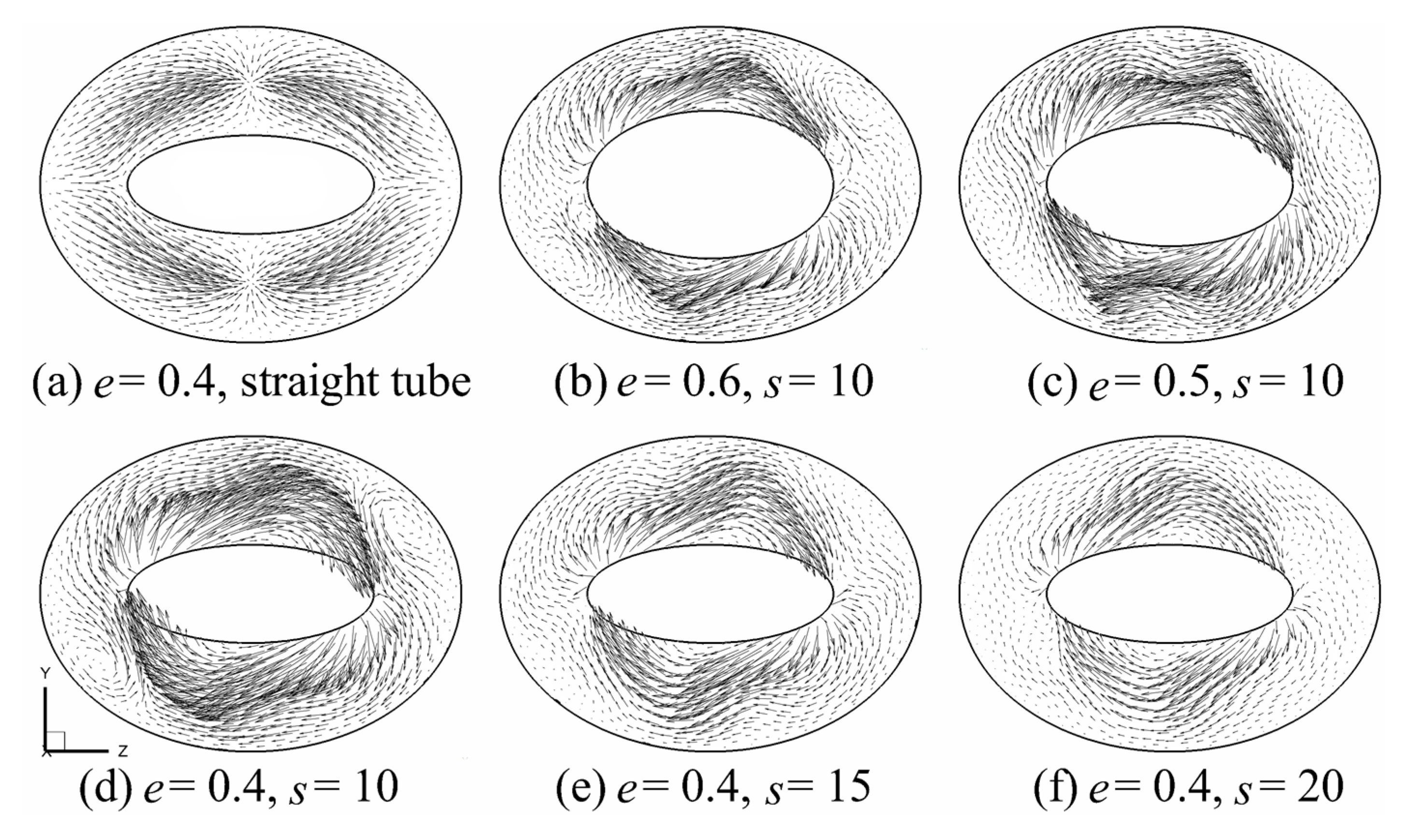
Figure 4 shows the secondary flow in the annulus at x = 720 mm for different e and s with Re = 3000. The tube surfaces of the inner oval tube are marked as portion I and portion II, as indicated in Figure 1c. The result of the model with an inner straight tube is presented in Figure 4a for comparison. As both the outer and inner tubes are straight, the secondary flow is marginal in Figure 4a. Please note that the velocity legend in Figure 4a has been enlarged by 300 times compared with that in the other figures. It is apparent that there is obvious secondary flow with a large tangential velocity induced by the inner twisted oval tube. The secondary flow on the cross section is rotationally symmetric about the annulus center. The fluid with a large tangential velocity flows along portion II of the inner tube surface due to the twisting of the inner tube and separates from the tube around the short-axis ends. The secondary flow caused by the twisting inner tube increases with the decrease in e from 0.6 to 0.4, as shown in Figure 4b–d. For different values of s from 10 to 20, the secondary flow becomes weaker due to the decrease in the torsional deformation of the inner twisted tube, as shown in Figure 4d–f.
Figure 5 shows the secondary flow on the cross sections of the third twisted pitch period with e = 0.4, s = 10, and Re = 3000. The cross sections are selected with the inner oval tube twists rotated clockwise from 0 to 360 degrees with an interval of 45 degrees. The distributions of the secondary flow caused by the inner twisted oval tube are different for the different twisted angles due to the continuous changing of the annulus formed between the outer straight and inner twisted oval tubes. The fluid flows over the long-axis ends and changes direction in portion II due to the twisting of the oval tube. The tangential velocity in portion II first increases with the increasing of the twisting angle from 0 to 90 degrees, and then the tangential velocity decreases with the continuous increasing of the twisting angle from 90 to 180 degrees, as shown in Figure 5a–e. The reason is that the spacing between the inner and outer tubes decreases as the twisting angle increases from 0 to 90 degrees, and the spacing is the smallest when the long axes of the inner and outer oval tubes are perpendicular to each other. The tangential velocity reaches the largest value as shown in Figure 5c when the annular space is the narrowest. Then, the tangential velocity decreases with an increase in the space when the twist angle changes from 90 to 180 degrees. The distributions of the secondary flow in Figure 5e–i for the twisting angle in the range of 180–360 degrees are similar to those in the range of 0–180 degrees in Figure 5a–e.

3.2. Temperature in the Annular Space

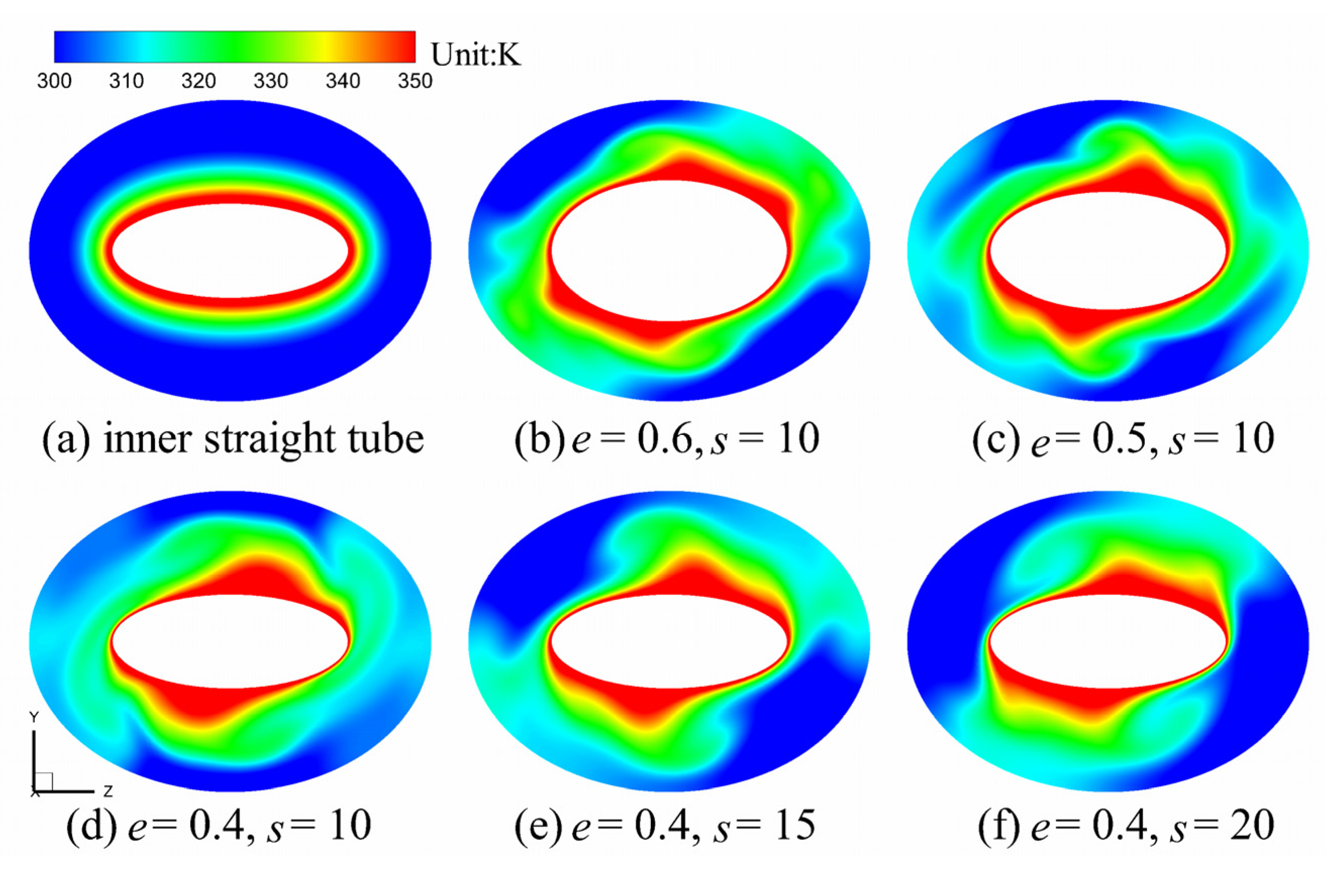
Figure 6 illustrates the cross-sectional temperature field with an identical position at x = 720 mm. The temperature field of the annulus with an inner straight tube is also shown for comparison. The inner twisted oval tube causes the fluid to flow rotationally and forms the secondary flow, which enhances the fluid mixing in the annulus. The temperature in the annulus of the model with an inner twisted tube is apparently larger than that with the inner straight tube. Moreover, the temperature contours are rotationally symmetric about the tube center of the inner twisted tube. Figure 6b–d present the cross-sectional temperature with an identical s = 10 and different aspect ratio e between 0.4 and 0.6. The temperature zone with a low value decreases with the decrease in e from 0.6 to 0.4. The temperature gradient in portion II around the long-axis ends of the inner tube increases as e decreases. This is because the thermal boundary layer on the inner tube wall is more obviously destroyed due to the large velocity and secondary flow when the value of e is small. Figure 6d–f present the effect of s on the temperature distribution with an identical aspect ratio e = 0.4. Since the twisted tube tends to be straight as s increases, the fluid mixing decreases due to the decrease in secondary flow. The temperature zone with a low value increases with increasing s. Thus, it can be concluded that the inner tube with smaller values of e and s can significantly improve the fluid mixing in the annulus.
The temperature fields of the third twist pitch period, in which the inner tube twists clockwise from 0 to 360 degrees, are shown in Figure 7 with e = 0.4, s = 10, and Re = 3000. There is a clear difference in the distribution of temperature along the inner tube surface. The temperature fields on all the sections are rotationally symmetric about the tube center. The temperature gradient near portion II is much higher than that near portion I of the inner oval tube, and the temperature gradient near the short-axis ends of the inner oval tube is the smallest. This is because the fluid with low temperature changes direction and flows along portion II with large tangential velocity. The temperature increases gradually along portion II when the fluid flows from the long-axis ends to the short-axis ends, and then the fluid with high temperature flows over portion I from the short-axis ends of the inner tube. Thus, the temperature around portion I is much higher than that around portion II of the inner tube.

3.3. Effects of s and e on Nu and f

The distributions of Nu for different s with an identical e = 0.4 of the inner twisted tube are presented in Figure 8a. Nu for the annular tube with an inner straight tube is also shown to perform a comparison. The Nu of the inner straight tube first increases smoothly with increasing Re in laminar flow, and sharply increases when the flow changes from laminar to turbulent. Then, Nu increases smoothly again in turbulent flow. The Nu of the inner twisted tube increases sharply in both laminar and turbulent regimes as Re increases. The most significant increase in Nu occurs at the transition Re where the flow turns to turbulence. The Nu on the inner straight tube is much smaller than that on the inner twisted tube. The difference in Nu between the annuli with inner straight and twisted tubes increases with increasing Re in laminar flow, while the difference in the turbulent regime is not so large. Thus, the heat transfer in the annulus can be effectively improved by the inner twisted tube in the laminar regime. Nu increases as s decreases because stronger secondary flow, which can enhance the heat transfer, can be induced by the inner twisted tube with smaller s. The largest differences in Nu between different s are 26% and 14% in laminar and turbulent flows, respectively. Comparing with the case with an inner straight tube, the largest Nu of the twisted inner tube increases by 116% and 27% in laminar and turbulent flows, respectively.
Comparisons of Nu for different aspect ratios are presented in Figure 8b with an identical s = 10. The value of Nu for all of the annular tubes increases with increasing Re. There is small difference in Nu for the inner straight tube with different e, while the difference in Nu for the inner twisted tube between different e is quite obvious. The reason is that the difference in the secondary flow intensity caused by the inner twisted oval tube with different e is quite different, as shown in Figure 4. According to the previous study in [19], the secondary flow intensity corresponds to Nu. The value of Nu on the inner twisted tube is significantly larger than that on the inner straight tube owing to the much stronger secondary flow in the annulus. Nu decreases as e changes from 0.4 to 0.6; this is because the torsional deformation of the inner twisted oval tube decreases with the increase in the twist ratio, and the secondary flow in the annulus also decreases. The largest difference in Nu between different inner twisted tubes is 35% at s = 10 and Re = 2000, while the largest difference in Nu is less than 6% between different inner straight tubes. The Nu of the inner twisted tubes with different e are 116%, 97%, and 82% higher than those of the corresponding straight tubes in the laminar regime, and 27%, 21%, and 15% higher than the straight tubes in the turbulent regime.
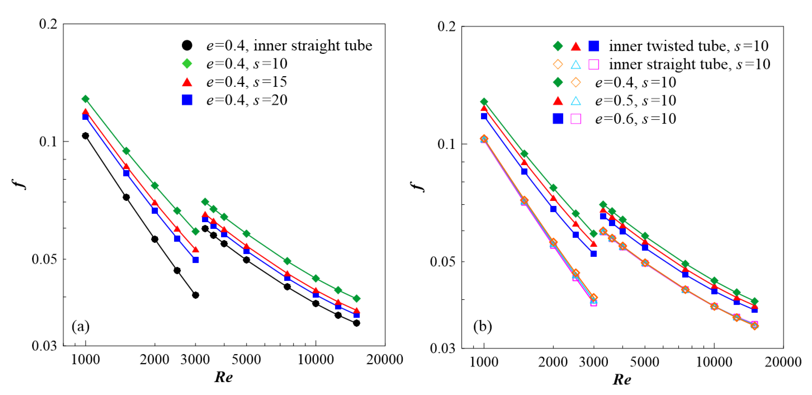
The distributions of f for different s together with f for the inner straight tube are presented in Figure 9a. The values of f for different values of s are obviously greater than the value for the inner straight tube. As the laminar flow changes to turbulence when Re > 3000, the f for turbulent flow is higher than that for laminar flow around Re = 3000. The f for the inner twisted tube increases as s decreases. The largest difference in f is 11.3% between the cases with s = 10 and s = 15 at Re = 3000, and the largest difference in f is only 6.4% between the cases with s = 15 and s = 20. The largest difference of 18% in f is between different s at e = 0.4 and Re = 3000. Figure 9b shows the comparison of f for different aspect ratios with an identical s = 10. The f of all the models decreases with increasing Re in both laminar and turbulent regimes. The f for the inner twisted tube decreases with increasing e, while the difference in f for the inner straight tube is slight for different e. The reason is that there is a large difference in the secondary flow intensity generated by the twisted tubes with different e. The maximum difference in f is about 13% between different inner twisted tubes with s = 10, while the difference is less than 4% between different inner straight tubes. The largest difference in f is 46% between the inner twisted and straight tubes at s = 10, e = 0.4, and Re = 3000.

3.4. Effects of s and e on JF

Comparisons of the thermal performance factor JF defined in Equation (12) for different s and e are illustrated in Figure 10. JF first increases to a peak value within the Re range from 1000 to 3000. Then, JF decreases when the flow changes from a laminar to turbulent regime for Re > 3000. It can be seen that JF in the laminar regime is higher than that in the turbulent regime, which indicates that the improvement of the thermal performance in the laminar regime is higher than that in the turbulent regime. The value of JF increases with the decrease in both s and e. When Re = 2000, the differences in JF between different s and e are both the largest with 18% and 25%, respectively. The largest JF is about 1.9, which implies that the comprehensive thermal-hydraulic performance in the annulus with the inner twisted oval tube is 1.9 times higher that with the inner straight oval tube.

3.5. Correlations

The fitted correlations are summarized as follows:
For laminar flow:
N u = 0.85428 R e 0.37734 e 0.65584 s 0.29772
f = 30.66264 R e 0.76021 e 0.23232 s 0.18382
For turbulent flow:
N u = 0.08683 R e 0.69524 e 0.18294 s 0.13062
f = 1.3896 R e 0.35418 e 0.10164 s 0.11376
The correlations are applicable for 10 ≤ s ≤ 20 and 0.4 ≤ e ≤ 0.6, and are valid for laminar flow for 1000 ≤ Re ≤ 3000, and for 3000 < Re ≤ 15,000 for turbulent flow with the fixed outer straight oval tube of the annular tube. Figure 11 illustrates the comparison of the correlations and numerical results. The largest deviations are within ±5% and ±4% for Nu and f, respectively.

4. Conclusions

Thermal performance in a novel annulus was numerically studied. The annulus is formed by outer straight and inner twisted oval tubes. The primary conclusions are summarized as follows.
(1)
The fluid mixing in the annulus is obviously improved by the inner twisted oval tube.
(2)
Nu and f increase as both the aspect ratio and twist ratio decrease. The largest relative increments of Nu and f are 35% and 13% between different aspect ratios, and 26% and 18% between different twist ratios.
(3)
The inner twisted oval tube yields 116% and 46% increases in Nu and f, respectively, compared with the inner straight tube.
(4)
The thermal performance enhancement is more significant in the laminar regime. The largest JF = 1.9 is obtained for aspect ratio 0.4 and twist ratio 10 at Re = 3000, which is the largest Re in the laminar regime.
(5)
The deviations for Nu and f of the correlations are within ±5% and ±4%, respectively.

Author Contributions

Conceptualization, K.S. and T.T.; investigation, C.L., and T.L.; original draft, C.L. and K.S.; review and editing, T.T. and K.S.; project administration, K.S. All authors have read and agreed to the published version of the manuscript.

Funding

This work was supported by the Natural Science Foundation of China (51866007), the Collaborative Innovation Team Project (2018C-13) of Gansu Province, and the Foundation of A Hundred Youth Talents Training Program of Lanzhou Jiaotong University.

Conflicts of Interest

The authors declare no conflict of interest.

Nomenclature

aolong-axis length of outer tube, m
ailong-axis length of inner tube, m
Across-sectional area, m2
boshort-axis length of outer tube, m
bishort-axis length of inner tube, m
Dhhydraulic diameter, m
easpect ratio
ffriction factor
Gkturbulent kinetic energy due to mean velocity gradient, J/kg
hiheat transfer coefficient, W/(m2 K)
JFthermal performance factor
kturbulent kinetic energy, J/kg
Llength of the annular domain, m
LPwetted perimeter, m
NuNusselt number
Δppressure loss, Pa
Plength of twisted pitch, m
qwall heat flux, W/m2
ReReynolds number
stwist ratio
Sfin surface area, m2
Ttemperature, K
Tsbulk temperature, K
u, v, wcomponents of velocity vector, m/s
Xnon-dimensional distance
x, y, zcoordinates, m
Greek symbols
εturbulent dissipation rate, J/(kg s)
λthermal conductivity, W/(m K)
μdynamic viscosity, kg/(m s)
ρdensity, kg/m3
Subscripts
0straight inner and outer oval tubes
ininlet
tturbulent
wwall surface

References

  1. Omidi, M.; Farhadi, M.; Jafari, M. A comprehensive review on double pipe heat exchangers. Appl. Therm. Eng. 2017, 110, 1075–1090. [Google Scholar] [CrossRef]
  2. Setareh, M.; Saffar-Avval, M.; Abdullah, A. Experimental and numerical study on heat transfer enhancement using ultrasonic vibration in a double-pipe heat exchanger. Appl. Therm. Eng. 2019, 159, 113867. [Google Scholar] [CrossRef]
  3. Bahiraei, M.; Hangi, M. Investigating the efficacy of magnetic nanofluid as a coolant in double-pipe heat exchanger in the presence of magnetic field. Energy Convers. Manag. 2013, 76, 1125–1133. [Google Scholar] [CrossRef]
  4. Mousavi, S.V.; Sheikholeslami, M.; Bandpy, M.G.; Gerdroodbary, M.B. The Influence of magnetic field on heat transfer of magnetic nanofluid in a sinusoidal double pipe heat exchanger. Chem. Eng. Res. Des. 2016, 113, 112–124. [Google Scholar] [CrossRef]
  5. Bezaatpour, M.; Goharkhah, M. Convective heat transfer enhancement in a double pipe mini heat exchanger by magnetic field induced swirling flow. Appl. Therm. Eng. 2020, 167, 114801. [Google Scholar] [CrossRef]
  6. Zhang, S.J.; Lu, L.; Dong, C.S.; Cha, S.H. Thermal characteristics of perforated self-rotating twisted tapes in a double-pipe heat exchanger. Appl. Therm. Eng. 2019, 162, 114296. [Google Scholar] [CrossRef]
  7. Mashoofi, N.; Pourahmad, S.; Pesteei, S.M. Study the effect of axially perforated twisted tapes on the thermal performance enhancement factor of a double tube heat exchanger. Case Stud. Therm. Eng. 2017, 10, 161–168. [Google Scholar] [CrossRef]
  8. Sheikholeslami, M.; Ganji, D.D. Heat transfer improvement in a double pipe heat exchanger by means of perforated turbulators. Energy Convers. Manag. 2016, 127, 112–123. [Google Scholar] [CrossRef]
  9. Song, K.W.; Tagawa, T. The optimal arrangement of vortex generators for best heat transfer enhancement in flat-tube-fin heat exchanger. Int. J. Therm. Sci. 2018, 132, 355–367. [Google Scholar] [CrossRef]
  10. Song, K.W.; Xi, Z.P.; Su, M.; Wang, L.C.; Wu, X.; Wang, L.B. Effect of geometric size of curved delta winglet vortex generators and tube pitch on heat transfer characteristics of fin-tube heat exchanger. Exp. Therm. Fluid Sci. 2017, 82, 8–18. [Google Scholar] [CrossRef]
  11. Song, K.W.; Wang, L.; Hu, Y.J.; Liu, Q. Flow symmetry and heat transfer characteristics of winglet vortex generators arranged in common flow up configuration. Symmetry 2020, 12, 247. [Google Scholar] [CrossRef] [Green Version]
  12. Bhadouriya, R.; Agrawal, A.; Prabhu, S.V. Experimental and numerical study of fluid flow and heat transfer in a twisted square duct. Int. J. Heat Mass Transf. 2015, 82, 143–158. [Google Scholar] [CrossRef]
  13. Yang, S.; Zhang, L.; Xu, H. Experimental study on convective heat transfer and flow resistance characteristics of water flow in twisted elliptical tubes. Appl. Therm. Eng. 2011, 31, 2981–2991. [Google Scholar] [CrossRef]
  14. Cheng, J.L.; Qian, Z.Q.; Wang, Q. Analysis of heat transfer and flow resistance of twisted oval tube in low Reynolds number flow. Int. J. Heat Mass Transf. 2017, 109, 761–777. [Google Scholar] [CrossRef]
  15. Song, K.W.; Wang, L.B. Relationship between heat transfer intensity and absolute vorticity flux intensity in flat tube bank fin channels with Vortex Generators. Prog. Comput. Fluid Dyn. Int. J. 2008, 8, 496–502. [Google Scholar] [CrossRef]
  16. Song, K.W.; Wang, L.B. The effectiveness of secondary flow produced by vortex generators mounted on both surfaces of the fin to enhance heat transfer in a flat tube bank fin heat exchanger. J. Heat Transf. 2013, 135, 041902. [Google Scholar] [CrossRef]
  17. Hu, W.L.; Song, K.W.; Guan, Y.; Chang, L.M.; Liu, S.; Wang, L.B. Secondary flow intensity determines Nusselt number on the fin surfaces of circle tube bank fin heat exchanger. Int. J. Heat Mass Transf. 2013, 62, 620–631. [Google Scholar] [CrossRef]
  18. Song, K.W.; Liu, S.; Wang, L.B. Interaction of counter rotating longitudinal vortices and the effect on fluid flow and heat transfer. Int. J. Heat Mass Transf. 2016, 93, 349–360. [Google Scholar] [CrossRef]
  19. Song, K.W.; Hu, W.L.; Liu, S.; Wang, L.B. Quantitative relationship between secondary flow intensity and heat transfer intensity in flat-tube-and-fin air heat exchanger with vortex generators. Appl. Therm. Eng. 2016, 103, 1064–1070. [Google Scholar] [CrossRef]
  20. Esmaeilzadeh, E.; Almohammadi, H.; Nokhosteen, A.; Motezaker, A.; Omrani, A.N. Study on heat transfer and friction factor characteristics of γ-Al2O3/water through circular tube with twisted tape inserts with different thicknesses. Int. J. Therm. Sci. 2014, 82, 72–83. [Google Scholar] [CrossRef]
  21. Man, C.Z.; Yao, J.Y.; Wang, C. The experimental study on the heat transfer and friction factor characteristics in tube with a new kind of twisted tape insert. Int. Commun. Heat Mass Transf. 2016, 75, 124–129. [Google Scholar] [CrossRef]
  22. Pourahmad, S.; Pesteei, S.M. Effectiveness-NTU analyses in a double tube heat exchanger equipped with wavy strip considering various angles. Energy Convers. Manag. 2016, 123, 462–469. [Google Scholar] [CrossRef]
  23. Zhang, Z.; Ding, Y.M.; Guan, C.F.; Yan, H.; Yang, W.M. Heat transfer enhancement in double-pipe heat exchanger by means of rotor-assembled strands. Chem. Eng. Process. Process Intensif. 2012, 60, 26–33. [Google Scholar] [CrossRef]
  24. Bhadouriya, R.; Agrawal, A.; Prabhu, S.V. Experimental and numerical study of fluid flow and heat transfer in an annulus of inner twisted square duct and outer circular pipe. Int. J. Therm. Sci. 2015, 94, 96–109. [Google Scholar] [CrossRef]
  25. Bashtani, I.; Esfahani, J.A. ε-NTU analysis of turbulent flow in a corrugated double pipe heat exchanger: A numerical investigation. Appl. Therm. Eng. 2019, 159, 113886. [Google Scholar] [CrossRef]
  26. Zambaux, J.A.; Harion, J.L.; Russeil, S.; Bouvier, P. The effect of successive alternating wall deformation on the performance of an annular heat exchanger. Appl. Therm. Eng. 2015, 90, 286–295. [Google Scholar] [CrossRef]
  27. Wang, W.; Zhang, Y.; Lee, K.S.; Li, B. Optimal design of a double pipe heat exchanger based on the outward helically corrugated tube. Int. J. Heat Mass Transf. 2019, 135, 706–716. [Google Scholar] [CrossRef]
  28. Gorman, J.M.; Krautbauer, K.R.; Sparrow, E.M. Thermal and fluid flow first-principles numerical design of an enhanced double pipe heat exchanger. Appl. Therm. Eng. 2016, 107, 194–206. [Google Scholar] [CrossRef]
  29. Qi, C.; Luo, T.; Liu, M.N.; Fan, F.; Yan, Y.Y. Experimental study on the flow and heat transfer characteristics of nanofluids in double-tube heat exchangers based on thermal efficiency assessment. Energy Convers. Manag. 2019, 197, 111877. [Google Scholar] [CrossRef]
  30. Sadeghianjahromi, A.; Kheradmand, S.; Nemati, H. Developed correlations for heat transfer and flow friction characteristics of louvered finned tube heat exchangers. Int. J. Therm. Sci. 2018, 129, 135–144. [Google Scholar] [CrossRef]
  31. Luo, C.; Wu, S.; Song, K.W.; Hua, L.; Wang, L.B. Thermo-hydraulic performance optimization of wavy fin heat exchanger by combining delta winglet vortex generators. Appl. Therm. Eng. 2019, 163, 114343. [Google Scholar] [CrossRef]
  32. Luo, C.; Song, K.W.; Tagawa, T.; Wu, X.; Wang, L.B. Thermal performance of a zig-zag channel formed by two wavy fins mounted with vortex generators. Int. J. Therm. Sci. 2020, 153, 106361. [Google Scholar] [CrossRef]
  33. Song, K.W.; Shi, W.N.; Wu, X.; Wang, L.B. Characteristics of flow symmetry and heat transfer of winglet pair in common flow down configuration. Symmetry 2020, 12, 209. [Google Scholar] [CrossRef] [Green Version]
  34. Song, K.W.; Tagawa, T.; Chen, Z.H.; Zhang, Q. Heat transfer characteristics of concave and convex curved vortex generators in the channel of plate heat exchanger under laminar flow. Int. J. Therm. Sci. 2019, 137, 215–228. [Google Scholar] [CrossRef]
  35. Song, K.W.; Wang, L.B. Effects of longitudinal vortex interaction on periodically developed flow and heat transfer of fin-and-tube heat exchanger. Int. J. Therm. Sci. 2016, 109, 206–216. [Google Scholar] [CrossRef]
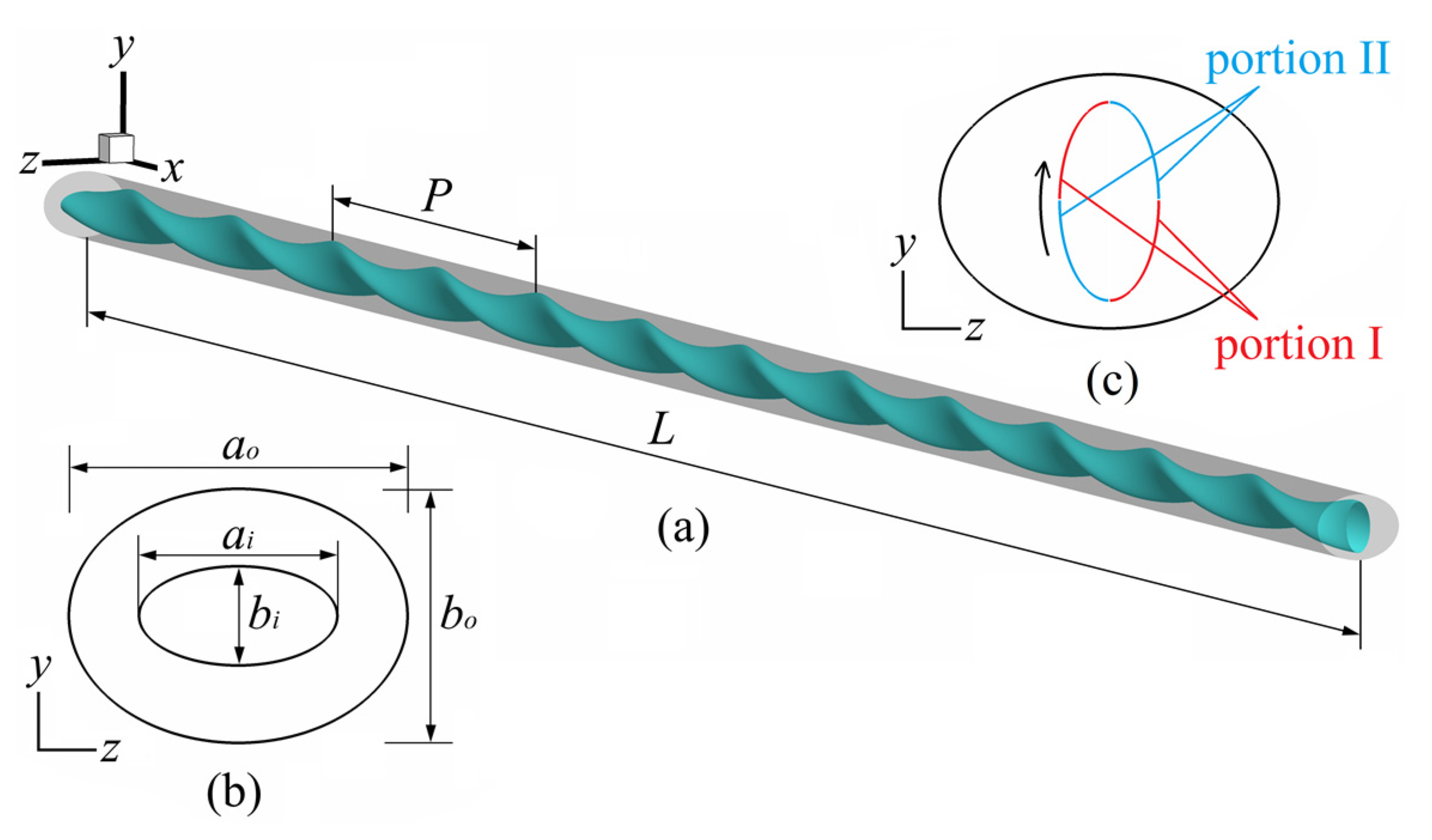
Figure 1. Physical model, (a) annular tube, (b) cross section, and (c) portion I and portion II of inner oval tube.
Symmetry 12 01213 g001
Figure 2. Grid independence study.
Symmetry 12 01213 g002
Figure 3. Grid system: (a) grid of outer tube and cross section, (b) grid of inner tube.
Symmetry 12 01213 g003
Figure 4. Comparison of secondary flow for different e and s at x = 720 mm with Re = 3000.
Symmetry 12 01213 g004
Figure 5. Secondary flow of the third twisted pitch period for e = 0.4, s = 10 at Re = 3000.
Symmetry 12 01213 g005
Figure 6. Temperature fields for different e and s at x = 720 mm with Re = 3000.
Symmetry 12 01213 g006
Figure 7. Temperature fields for cross sections of the third twisted pitch for e = 0.4, s = 10 at Re = 3000.
Symmetry 12 01213 g007
Figure 8. Comparison of Nu for different s and e: (a) different s; (b) different e.
Symmetry 12 01213 g008
Figure 9. Comparison of f for different s and e: (a) different s; (b) different e.
Symmetry 12 01213 g009
Figure 10. Comparison of JF for different s and e: (a) s; (b) e.
Symmetry 12 01213 g010
Figure 11. Comparison of correlations and numerical results: (a) Nu; (b) f.
Symmetry 12 01213 g011
Table 1. Validation of present study.
Calculation ModelLaminar, Re = 1000RNG kε, Re = 11,000
fReNufReNu
Experiment [24]22.74.4187.443.31
Present21.454.0197.3938.67
Relative error5.5%9.1%11.4%10.7%