Energy Dissipation Characteristics and Parameter Identification of Symmetrically Coated Damping Structure of Pipelines under Different Temperature Environment


Abstract
:1. Introduction
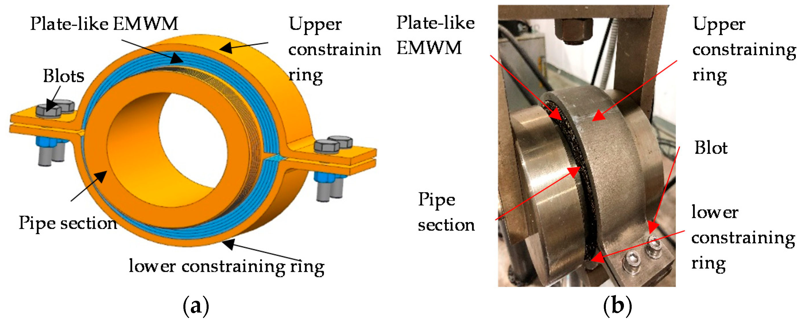
2. Design of the Symmetrically Coated Damping Structure for EMWM of Pipelines
3. Specimen and Test Design
3.1. EMWM Specimen
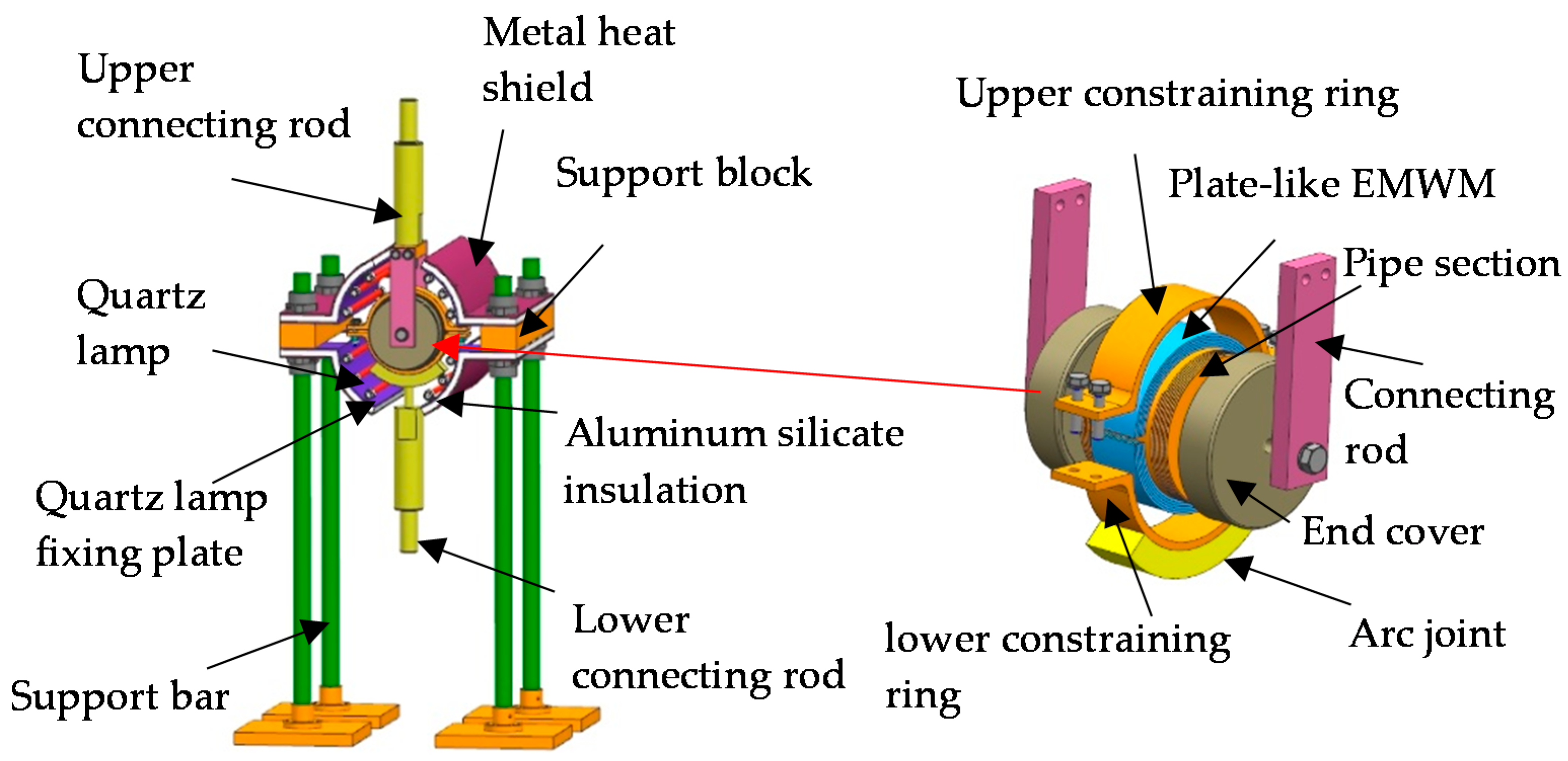
3.2. Test System
3.3. Test Methods
4. Energy Dissipation Test Results and Discussion
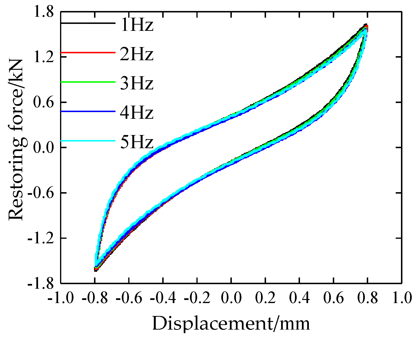
4.1. The Influence of the Vibration Frequency
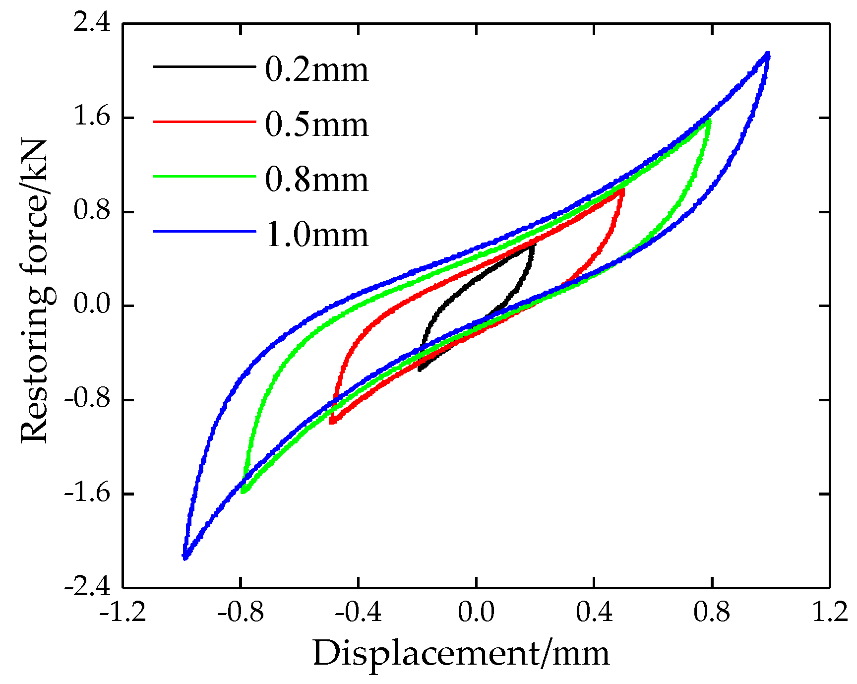
4.2. The Influence of the Vibration Amplitude
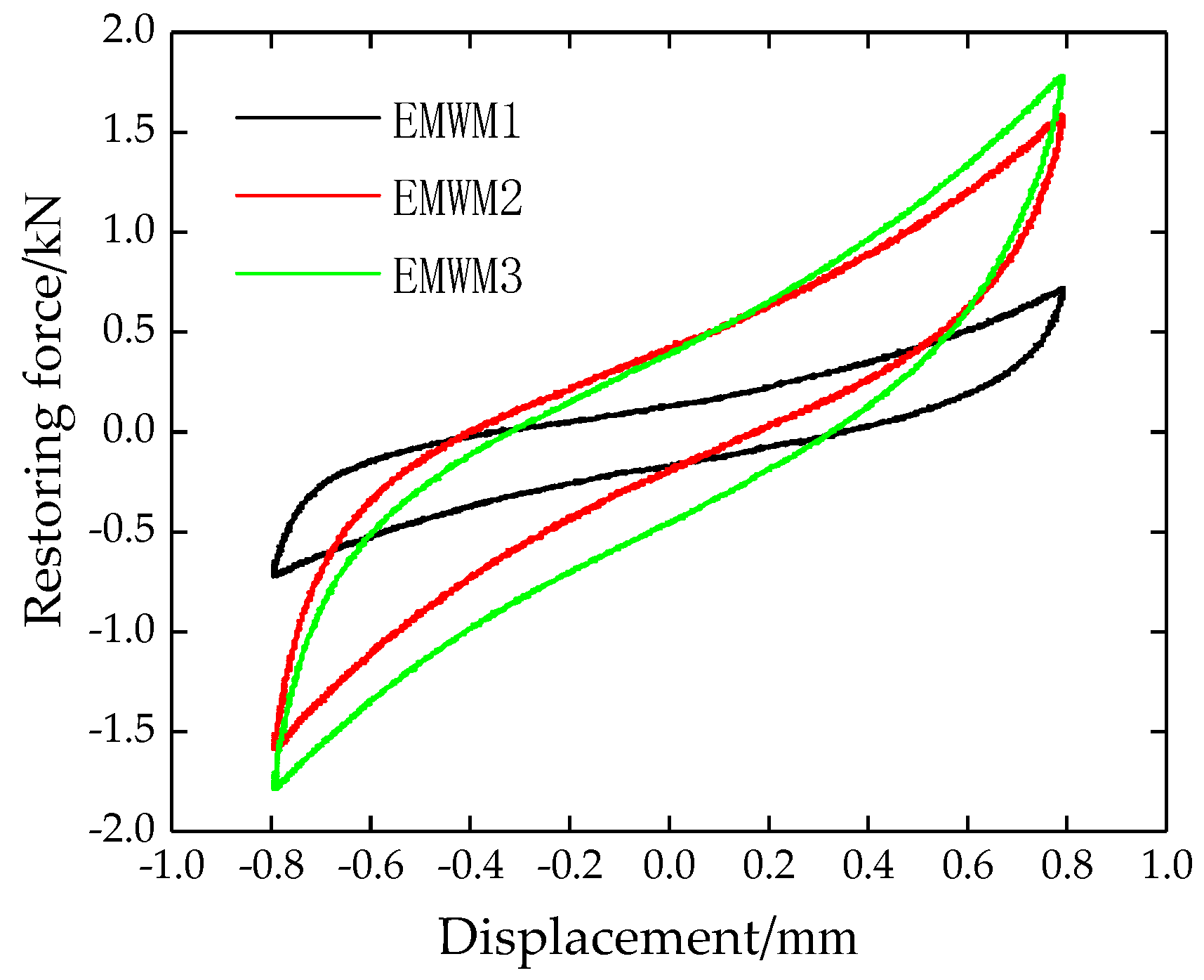
4.3. The Influence of the Density
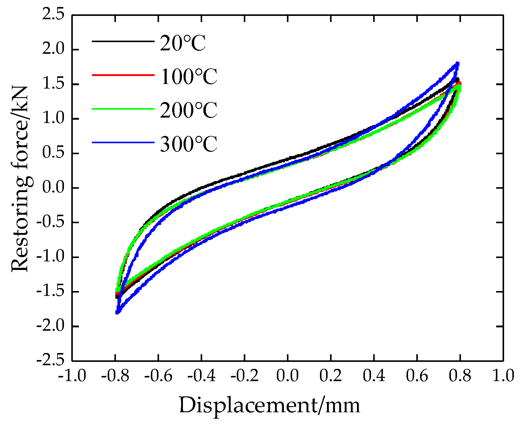
4.4. The Influence of Temperature
5. Modeling and Parameter Identification
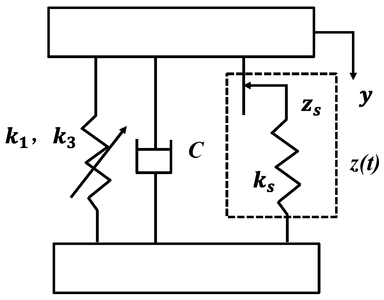
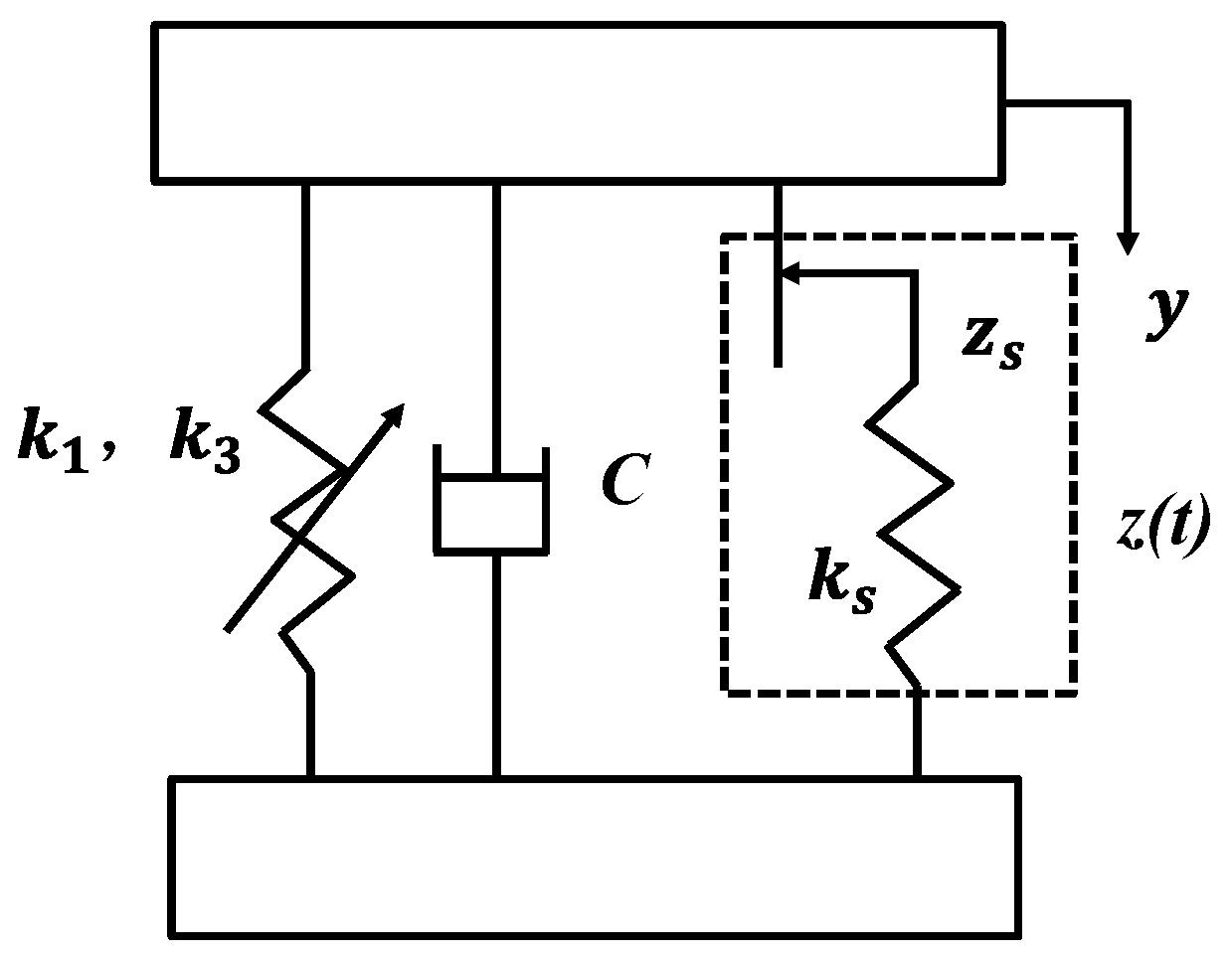
5.1. Modeling
5.2. Parameter Identification
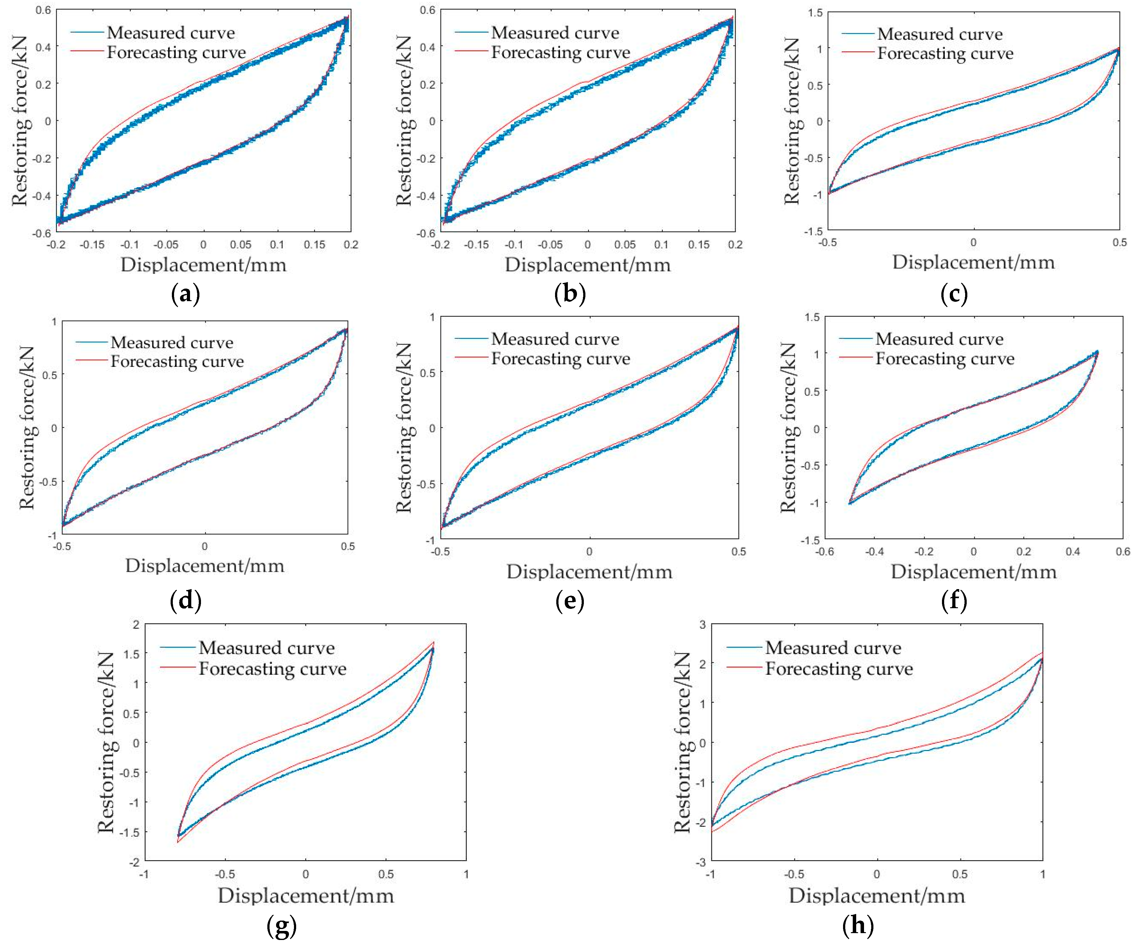
5.3. Model Verification
- (1)
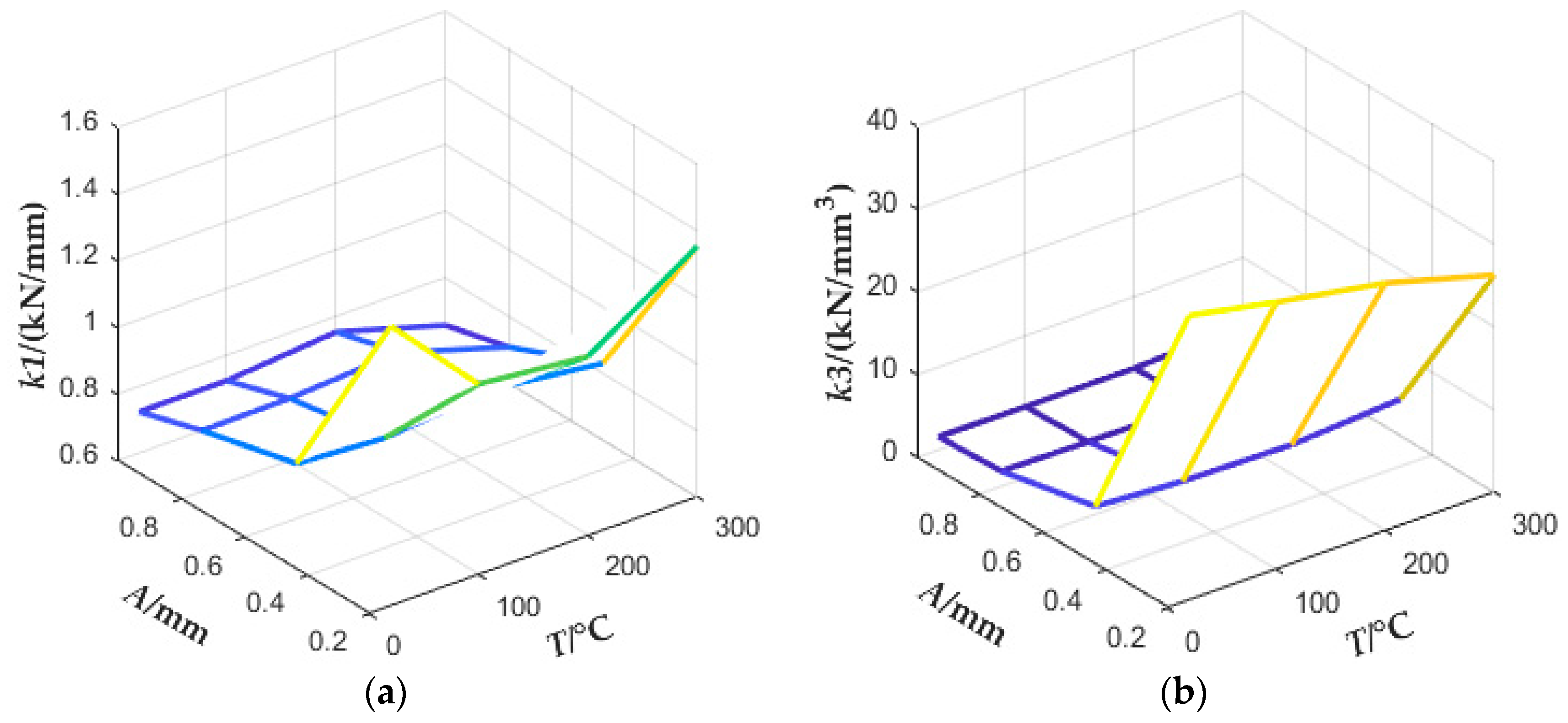
- The first-order stiffness coefficient k1(A,T) and the third-order stiffness coefficient k3(A,T) could describe the stiffness variation for symmetrically coated damping structure for EMWM of pipelines, and their variation with amplitude (A) and temperature (T) were consistent with the experimental results.
- (2)
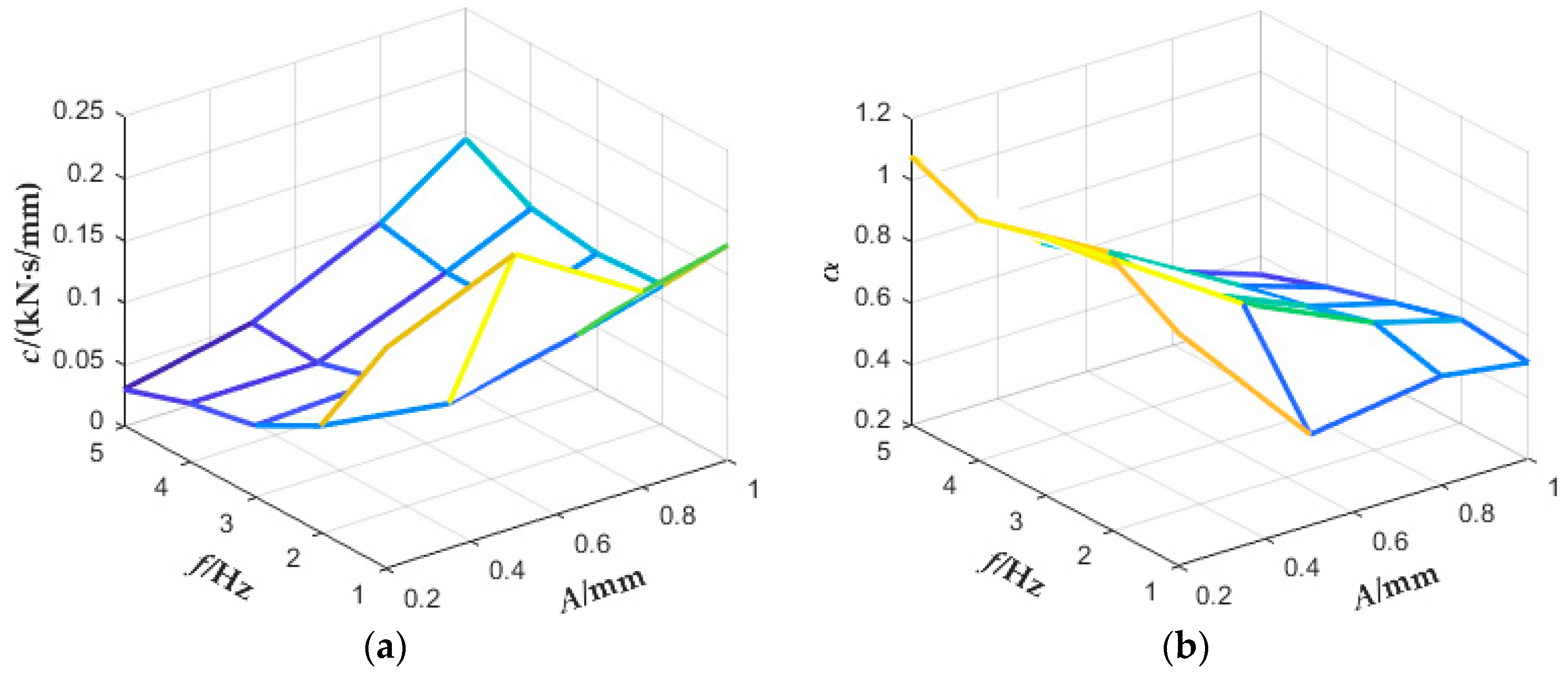
- The damping coefficient c and damping component factor α could describe the energy dissipation characteristics of symmetrically coated damping structure for EMWM of pipelines, and their variation with amplitude (A) and frequency (f) were consistent with the experimental results.
- (3)
- The proposed nonlinear functional constitutive relation model of symmetrically coated damping structure for EMWM of pipelines could properly describe the variation of restoring force with temperature (T), amplitude (A), frequency (f), displacement (y).
6. Conclusions
- (1)
- In the rage of 1–5 Hz, the influence of vibration frequency on symmetrically coated damping structure for EMWM of pipelines can be ignored.
- (2)
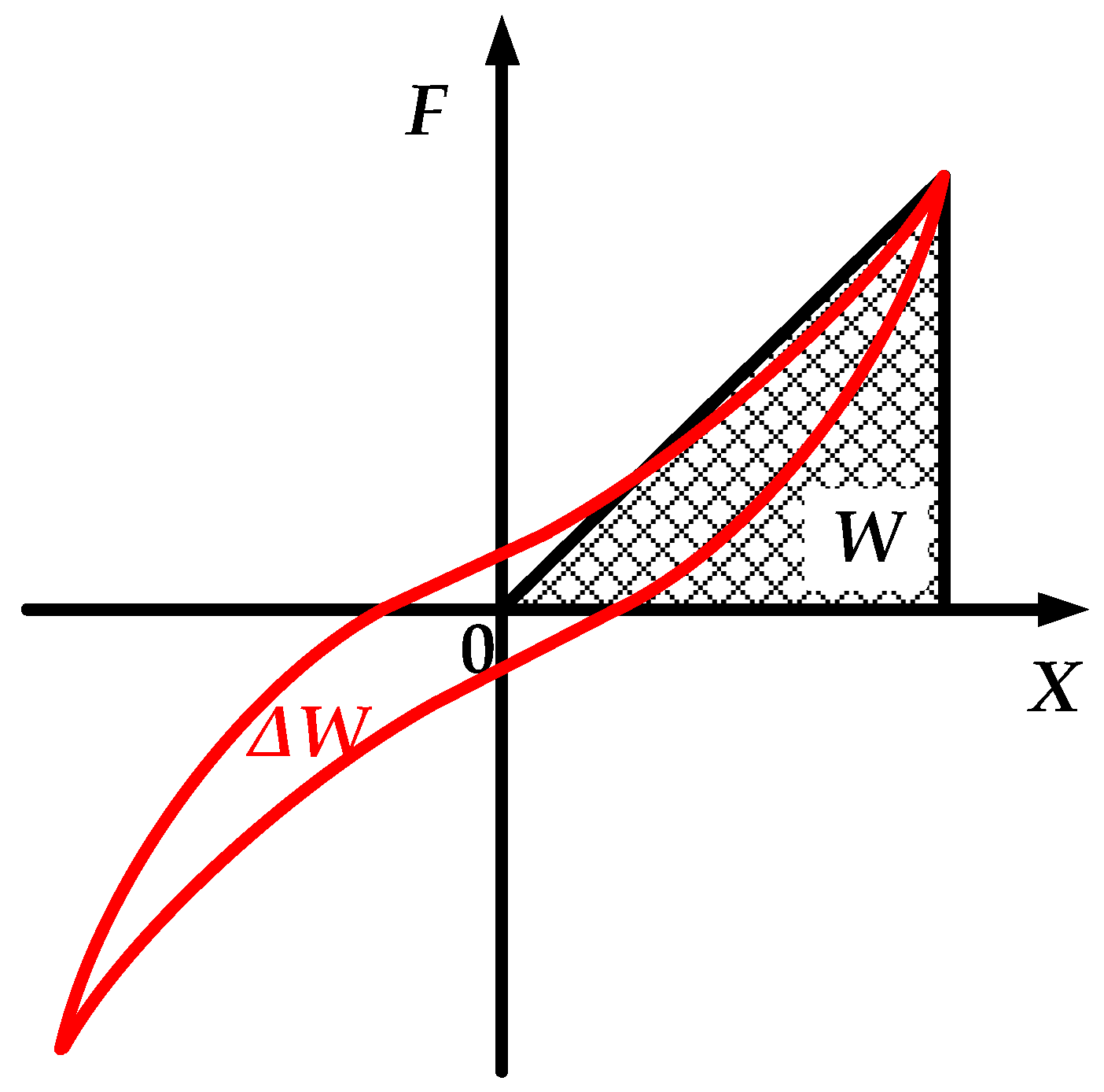
- With the increase of density, the loss factor (η) decreases at first and then increases, while the dissipated energy (ΔW) and the maximum elastic potential energy (W) increase gradually.
- (3)
- With the increase of temperature, the energy dissipation Δ W and the maximum elastic potential energy W decrease in the temperature range of 20–200 °C, and then increase in the temperature range of 200–300 °C, while the loss factor η decreases slightly in the temperature range of 20–300 °C.
- (4)
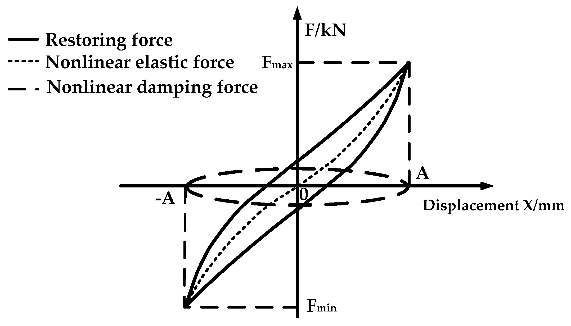
- Through the decomposition of the hysteretic loop, a revised energy dissipation model of symmetrically coated damping structure for EMWM of pipelines with temperature parameters was set up and was proved to properly describe the dynamic characteristics of the symmetrically coated damping structure for EMWM of pipelines by parameter identification and simulation.
Author Contributions
Funding
Conflicts of Interest
References
- Xie, Z.; Sebald, G.; Guyomar, D. Temperature dependence of the elastocaloric effect in natural rubber. Phys. Lett. A 2017, 81, 2112–2116. [Google Scholar] [CrossRef] [Green Version]
- Sakulkaew, K.; Thomas, A.G.; Busfield, J.J.C. The effect of temperature on the tearing of rubber. Polym. Test. 2013, 32, 86–93. [Google Scholar] [CrossRef]
- Ma, Y.H.; Zhang, Q.C.; Wang, Y.F.; Hong, J.; Scarpa, F. Topology and mechanics of metal rubber via x-ray tomography. Mater. Des. 2019, 181, 108067. [Google Scholar] [CrossRef]
- Zhang, Q.C.; Zhang, D.Y.; Dobah, Y.; Scarpa, F.; Fraternali, F.; Skelton, R.E. Tensegrity cell mechanical metamaterial with metal rubber. Appl. Phys. Lett. 2018, 113, 031906. [Google Scholar] [CrossRef] [Green Version]
- Hu, J.L.; Du, Q.; Gao, J.H.; Kang, J.Y.; Guo, B.T. Compressive mechanical behavior of multiple wire metal rubber. Mater. Des. 2018, 140, 231–240. [Google Scholar] [CrossRef]
- Zarzour, M.; Vance, J. Experimental evaluation of a metal mesh bearing damper. J. Eng. Gas Turbines Power 2000, 122, 326–329. [Google Scholar] [CrossRef]
- Chandrasekhar, K.; Rongong, J.; Cross, E. Mechanical behaviour of tangled metal wire devices. Mech. Syst. Signal Process. 2019, 118, 13–29. [Google Scholar] [CrossRef] [Green Version]
- Wu, Y.W.; Li, S.Z.; Bai, H.B.; Jiang, L.; Cheng, H. Experimental and constitutive model on dynamic compressive mechanical properties of entangled metallic wire material under low-velocity impact. Materials 2020, 13, 1396. [Google Scholar] [CrossRef] [PubMed] [Green Version]
- DellaCorte, C. Oil-free shaft support system rotordynamics: Past, present and future challenges and opportunities. Mech. Syst. Signal Process. 2012, 29, 67–76. [Google Scholar] [CrossRef] [Green Version]
- Lee, Y.B.; Park, D.J.; Kim, C.H.; Ryu, K. Rotordynamic characteristics of a micro turbo generator supported by air foil bearings. J. Micromech. Microeng. 2007, 17, 297–303. [Google Scholar] [CrossRef]
- Zhizhkin, A.M.; Zrelov, V.A.; Zrelov, V.V.; Ardakov, A.Y.; Osipov, A.A. Rotor sealings based on a metal–rubber elastic porous material for turbomachinery. J. Frict. Wear 2018, 39, 259–263. [Google Scholar] [CrossRef]
- Ding, Z.Y.; Bai, H.B.; Wu, Y.W.; Ren, Z.Y.; Shao, Y.C. A constitutive model of plate-like entangled metallic wire material in wide temperature range. Materials 2019, 12, 2538. [Google Scholar] [CrossRef] [PubMed] [Green Version]
- Hou, J.F.; Bai, H.B.; Li, D.W. Damping capacity measurement of elastic porous wire-mesh material in wide temperature range. J. Mater. Process. Tech. 2008, 206, 412–418. [Google Scholar] [CrossRef]
- Zhu, Y.; Wu, Y.W.; Bai, H.B.; Ding, Z.Y.; Shao, Y.C. Research on vibration reduction design of foundation with entangled metallic wire material under high temperature. Shock Vib. 2019, 2019, 1–16. [Google Scholar] [CrossRef]
- Bai, H.B.; Lu, C.H.; Cao, F.L.; Li, D.W. Material and Engineering Application of Metal Rubber; Science Press: Beijing, China, 2014. [Google Scholar]
- Xiao, K.; Bai, H.B.; Xue, X.; Wu, Y.W. Damping characteristics of metal rubber in the pipeline coating system. Shock Vib. 2018, 2018, 1–11. [Google Scholar] [CrossRef] [Green Version]
- Wu, K.A.; Bai, H.B.; Xue, X.; Li, T.; Li, M. Energy dissipation characteristics and dynamic modeling of the coated damping structure for metal rubber of bellows. Metals 2018, 8, 562. [Google Scholar] [CrossRef] [Green Version]
- Ulanov, A.M.; Bezborodov, S.A. Calculation method of pipeline vibration with damping supports made of the MR material. Procedia Eng. 2016, 150, 101–106. [Google Scholar] [CrossRef] [Green Version]
- Wu, Y.W.; Jiang, L.; Bai, H.B.; Lu, C.H.; Li, S.Z. Mechanical Behavior of Entangled Metallic Wire Materials under Quasi-Static and Impact Loading. Materials 2019, 12, 3392. [Google Scholar] [CrossRef] [Green Version]
- Wang, Y.Y.; Bai, H.B.; Liu, Y.F. Study on Microscopic Characteristics of Compressive Properties of Metal Rubber Materials. Mech. Sci. Technol. 2011, 30, 404–407. [Google Scholar]


| Specimen | Weight | Molding Pressure (kN/cm2) | Molding Density (g/cm3) |
|---|---|---|---|
| EMWM1 | 70 g | 5.71 | 2.0 |
| EMWM2 | 80 g | 8.57 | 2.286 |
| EMWM3 | 90 g | 14.29 | 2.571 |
| Frequency/Hz | Loss Factor η | Dissipated Energy ΔW | Maximum Elastic Potential Energy W |
|---|---|---|---|
| 1 | 0.2404 | 0.9813 | 0.6497 |
| 2 | 0.2402 | 0.9744 | 0.6456 |
| 3 | 0.2442 | 0.9696 | 0.6318 |
| 4 | 0.2480 | 0.9729 | 0.6243 |
| 5 | 0.2515 | 0.9790 | 0.6195 |
| Amplitude/mm | Loss Factor η | Dissipated Energy ΔW | Maximum Elastic Potential Energy W |
|---|---|---|---|
| 0.2 | 0.3708 | 0.1281 | 0.0550 |
| 0.5 | 0.3126 | 0.4905 | 0.2498 |
| 0.8 | 0.2442 | 0.9696 | 0.6318 |
| 1 | 0.2004 | 1.3499 | 1.0723 |
| Specimen | Loss Factor η | Dissipated Energy ΔW | Maximum Elastic Potential Energy W |
|---|---|---|---|
| EMWM1 | 0.2732 | 0.4938 | 0.2876 |
| EMWM2 | 0.2442 | 0.9696 | 0.6318 |
| EMWM3 | 0.2741 | 1.2217 | 0.7092 |
| Temperature/°C | Loss Factor η | Dissipated Energy ΔW | Maximum Elastic Potential Energy W |
|---|---|---|---|
| 20 | 0.2442 | 0.9696 | 0.6318 |
| 100 | 0.2237 | 0.8675 | 0.6173 |
| 200 | 0.2280 | 0.8543 | 0.5964 |
| 300 | 0.2075 | 0.9415 | 0.7223 |
© 2020 by the authors. Licensee MDPI, Basel, Switzerland. This article is an open access article distributed under the terms and conditions of the Creative Commons Attribution (CC BY) license (http://creativecommons.org/licenses/by/4.0/).
Share and Cite
Jiang, F.; Ding, Z.; Wu, Y.; Bai, H.; Shao, Y.; Zi, B. Energy Dissipation Characteristics and Parameter Identification of Symmetrically Coated Damping Structure of Pipelines under Different Temperature Environment. Symmetry 2020, 12, 1283. https://doi.org/10.3390/sym12081283
Jiang F, Ding Z, Wu Y, Bai H, Shao Y, Zi B. Energy Dissipation Characteristics and Parameter Identification of Symmetrically Coated Damping Structure of Pipelines under Different Temperature Environment. Symmetry. 2020; 12(8):1283. https://doi.org/10.3390/sym12081283
Chicago/Turabian StyleJiang, Feng, Zheyu Ding, Yiwan Wu, Hongbai Bai, Yichuan Shao, and Bao Zi. 2020. "Energy Dissipation Characteristics and Parameter Identification of Symmetrically Coated Damping Structure of Pipelines under Different Temperature Environment" Symmetry 12, no. 8: 1283. https://doi.org/10.3390/sym12081283