Abstract
To ensure the security of digital images during transmission and storage, an efficient and secure chaos-based color image encryption scheme using bit-level permutation is proposed. Our proposed image encryption algorithm belongs to symmetric cryptography. Here, we process three color components simultaneously instead of individually, and consider the correlation between them. We propose a novel bit-level permutation algorithm that contains three parts: a plain-image related rows and columns substitution, a pixel-level roll shift part, and a bit-level cyclic shift part. In the plain-related rows and columns substitution part, we involve the plain-image information to generate a control sequence by using a skew tent system. This process ensures that the correlation between three color components can be totally broken, and our cryptosystem has enough plain-image sensitivity to resist the differential attack. In the pixel-level roll shift part and bit-level cyclic shift part, we have a fully bit-level permutation controlled by two sequences using a Rucklidge system. The simulation and some common security analyses are given. Test results show that our proposed scheme has good security performance and a speed advantage compared to other works.
1. Introduction
Color images, as a kind of multimedia format, have become the most important information carrier in digital communication, increasing the convenience of daily life. The security problem of color images in transmission and cloud storage should not be ignored; therefore, digital image encryption has become an important research topic in the field of multimedia network communication.
There are different features between image and text structure data, such as high redundancy, strong correlation among adjacent pixels, etc. Thus, many traditional text structure encryption schemes result in poor performance on image encryption [1]. Therefore, many encryption algorithms designed for image features have been proposed [2]. Previously, an image encryption scheme only used special transformation matrices (e.g., Arnold map, magic cube transformation, etc.) to change the position of pixels in the plain image, but these schemes did not meet Kerckhoffs’s principle. According to Kerckhoffs’ principle, a modern cryptosystem should make all details public knowledge, as the system security only depends on the key. These schemes are also unable to resist statistical attacks and known plaintext attacks [3].
According to Shannon’s theory [4], a good encryption system should contain two processes: permutation and diffusion. There are two types of permutation methods: one is the pixel-level permutation, which only changes the pixels’ positions; the other is the bit-level permutation, which not only changes the positions, but also changes the values of the pixels. The diffusion process is a necessary step in ensuring the plaintext and security key are fully diffused.
Many fields have found the chaotic phenomenon since Lorenz [5] proposed the chaos theory, including medicine, biology, chemistry, astronomy, physics, etc. As a result of its many good properties, such as sensitivity to initial values and parameters, randomness, ergodicity, etc., chaotic systems are suitable for designing an image cryptosystem belonging to symmetric cryptography. Since the first chaotic image encryption scheme was proposed by Matthews [6], a large number of image encryption algorithms based on chaos theory have been put forward [7,8,9,10,11,12,13,14,15,16,17,18,19,20,21,22,23,24,25,26,27,28,29,30,31,32,33].
There are two mainstream research directions. One direction is pixel image encryption [7,8,9,10,11,12,13,14,15,16,17,18,19,20,21,29,30,31,32], which for some applications, must be transported in pixel form, e.g., remote sensing images. The other direction is encryption on a compressed image, e.g., image applications on the internet [23,24,25,26,27,28,29]. In [1], a plain image-related encryption method was given; this scheme performed well for resisting a differential attack. However, this scheme has an obvious shortcoming—it hides the quantization value generated by the plain image in two pixels of the cipher image. It can cause security problems and information loss. Patidar et al. [3] presented a substitution–diffusion-based image cipher using chaotic standard and logistic maps. Lee et al. [7] proposed image encryption based on a lightweight chaotic system and simple arithmetic operation to achieve high encryption speed. Ullah et al. [8] designed a scheme for image encryption using a chaotic system and S-box. Devaraj et al. [9] designed a dynamic S-box using a modified standard map, and then proposed a color image encryption scheme using this dynamic S-box. Although this scheme has good security performance, its encryption efficiency is not fast enough. Guesmi et al. [10] used chaos theory, a DNA sequence operation, and hash function SHA-2 to design an image encryption scheme. This scheme takes advantage of the parallel features of DNA computing. However, the DNA encoding process and hash function increase the computational complexity.
Hu et al. [11] proposed a bit-level permutation strategy using a dynamic lookup table, and then provided an image encryption algorithm based on their theory. This scheme reduces bit-level permutation computational complexity using a look-up table. Hu et al. [12] defined a novel DNA sequence operation, and then they proposed an image cryptosystem based on chaotic map and this operation. The image DNA encoding and decoding processes are achieved through DSP (Digital Signal Processor), thereby improving the efficiency of those processes. Li et al. [13] proposed an image encryption scheme based on a chaotic tent map. This scheme has a weak plaintext sensitivity for resisting a differential attack.
Souyah et al. [14] proposed an image cryptosystem combining cellular automata and weighted histogram. They used one random position pixel from the plain image to store the weighted histogram value, ensuring that the encryption scheme has a relationship with the plain image. In [15], the author proposed a novel color image cryptosystem that combines compression and encryption, and this system uses the discrete cosine transformation dictionary to represent the color image. Then, the encryption and compression are achieved using a hyper chaotic system. In [16], the simulated annealing algorithm was used to obtain the optimal pseudorandom sequences, and then based on this theory, they designed an image encryption scheme. In [17], an image encryption algorithm was designed using chaos theory and they proposed a ranks interweaving method. This scheme has good encryption efficiency, but its security keys have a strong inner relation; therefore, the key space of this cryptosystem is not as large as declared. Li et al. [20] proposed a plaintext-related image encryption scheme by designing reversible permutation and security key generation algorithms. Zhu et al. [21] proposed a new compound homogeneous hyper chaotic system, and used this proposed chaotic system to design an image encryption algorithm. Ye et al. [22] proposed an image encryption scheme by using a quaternion discrete fractional Hartley transform and an improved pixel adaptive diffusion method. In [23], the authors used block compressive sensing and singular value decomposition embedding to balance the security, compression, and robustness. In [24], an image encryption scheme is proposed using a 2D multiple parameter fractional discrete Fourier transform and 3D Arnold transform. You et al. [25] proposed a parallel image encryption scheme implemented in OpenCL. Ouyang et al. [26] proposed a method of impulsive synchronization of coupled delayed neural networks with actuator saturation, and designed an image encryption scheme using this method. In [27], the authors proposed a compressed sensing strategy based on a semi-tensor product and designed a visual security image encryption scheme. In [28], an image encryption scheme is proposed using compressive sensing and random numbers insertion. Zhang et al. [29] proposed a plaintext-related image encryption scheme by using a perceptron-like network. In [30], the authors proposed a color image encryption scheme based on a two dimensional nonlinear coupled map lattices system. Arpacı et al. [31] gave an image cryptosystem via a modified Chua’s circuit. Khan et al. [33] proposed an image encryption scheme based on Lorenz, Gingerbreadman chaotic map, and S8 permutation.
Due to color images containing red, green, and blue color components, there is a correlation among color components. Therefore, the color image encryption algorithm does not simply encrypt each color component, because it needs to destroy the correlation among the components. Furthermore, a good color image encryption scheme should consume less time than the summation of encrypting each color component; therefore, our proposed method considers the correlation among three color-components and bit-level permutated them at the same time, resulting in higher efficiency. The main contributions of this work are as follows: (1) a cross-color-components bit-level permutation method is presented; (2) a fast and secure color image encryption scheme is proposed, and (3) some common security analyses and comparisons are given.
The organization of this paper is as follows: In Section 2, the detailed descriptions of encryption and decryption algorithms are given. In Section 3, the simulation results of our proposed scheme, some common security analyses, and a comparison are given. In the last section, the conclusions of this paper are provided.
2. Proposed Scheme
In our proposed scheme, the image cryptosystem includes two parts: bit-level permutation and diffusion. There are two types of chaotic systems in these processes. The skew tent system, which is given in Equation (1), is used to generate two substitute control sequences which are employed in plain-related substitution. The Rucklidge system, which is given in Equation (2), is used to generate pixels’ positions shift control sequences and bit cycle shift control sequences which are employed in bit-level permutation. In addition, the Rucklidge system generates the security keys for encryption or decryption.
Remark: In our proposed scheme, we use a skew tent map and Rucklidge system to control the encryption process; other chaotic systems can also be extended in our scheme, and the only difference is the size of the key space.
The skew tent map [34] is given by:
where p is the parameter of the skew tent system. When , the system can generate a chaotic sequence .
The Rucklidge system [35] is given by:
where a and b are system parameters. When a = 2 and b = 7.7, the system enters into chaos and Figure 1 shows its attractors.
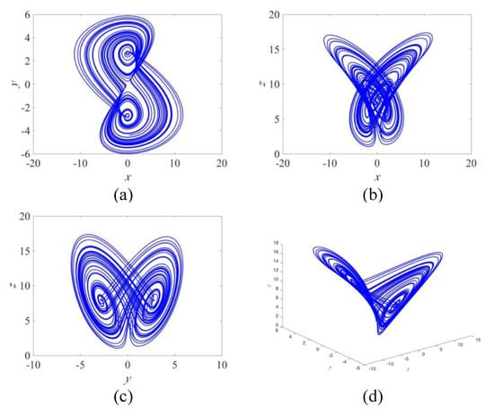
Figure 1.
Attractors of the Rucklidge system. (a) x–y plane, (b) x–z plane, (c) y–z plane, and (d) x–y–z plane.
2.1. Encryption Scheme
In this scheme, we used the traditional encryption architecture: permutation and diffusion. The permutation process contains three parts: plain-image related rows and columns substitution, pixel-level roll shift, and bit-level cyclic shift. Figure 2 shows the process of the encryption scheme. This process is described as follows:
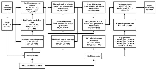
Figure 2.
The block diagram of encryption scheme.
(1) Input an RGB color plain image and the security keys into the encryption scheme. We assume that the size of the inputted image is M × N × 3. Then the encryption process begins.
Note, inputted security keys are defined as , which are used to generate parameters and initial values of the skew tent map and Rucklidge systems. To avoid a weak key problem, we required each input key to be 15 decimal places.
(2) Reshape the inputted color image from a 3D to 2D matrix, and denote it as PI.
where Red, Green, and Blue are color components. PI is an M × 3N matrix.
(3) Add all values of matrix PI, and denote the summation as SUM.
(4) The system parameter and initial condition of the skew tent map are generated by Equations (5) and (6), respectively.
where mod (a,1) means the decimal fraction from a, and k1, k2,…, k9 are the inputted keys (similarly hereinafter).
(5) Iterate Equation (1) under the system parameter and initial condition generated in Step 4, and then denote the iteration sequence (without the first 200 iterations) as T. Take the first M elements of T to generate a new sequence X1 (Equation (7)). Then, take the repeated numbers away from X1 and append the absent elements to the end for generating the rows’ substitute control sequence X. In the same way, take the M + 1 to M + 3N elements to generate a new sequence Y1 (Equation (8)). Then, take the repeated numbers away from Y1 and append the absent elements to the end for generating the columns’ substitute control sequence Y.
where mod (a, b) represents the remainder obtained on a/b, fix (a) represents the integer part of a, and T(a:b) means take the a to the b elements of T (similarly hereinafter).
(6) Partition matrix P into row vectors and denote them as , where t = 1, 2, …, M. Substitute the row vectors under X sequence controlling as in Equation (9).
(7) Repartition the row substituted matrix into column vectors and denote them as , where t = 1, 2, …, 3N. Substitute the column vectors under Y sequence controlling as in Equation (10).
(8) The initial conditions of the Rucklidge system are generated by Equations (11)–(13).
(9) Under the initial conditions generated in Step 8, iterate Equation (2) through a 0.002 step size 4th-order Runge–Kutta method. There are three sequences gained from this iteration. Discard the first 800 iterations to eliminate the transitional state, and denote the three sequences as XS, YS, and ZS, respectively. Here, the transitional state—some states before the chaos system goes stable—may cause the bad randomness seen in the generation sequences for the cryptosystem.
(10) Generate rows’ and columns’ pixel-level roll shifting control sequences by Equations (14) and (15), respectively.
(11) Generate rows’ and columns’ bit-level cyclic shifting control sequences by Equations (16) and (17), respectively.
(12) Partition the matrix generated in Step 7 into column vectors, and denote them as . Then, roll shift the pixels’ position as in Equation (18).
where i = 1, 2, …, 3N, and j = 1, 2, …, M.
(13) Denote the new column vectors generated in the previous step as . Then, cyclic shift all elements in the column vector to the left direction under the control sequence as in Equation (19).
(14) Repartition the matrix generated in the previous step into row vectors, and denote them as . Then, roll shift the pixels’ position as Equation (20).
where i = 1, 2, …, M, and j = 1, 2, …, 3N.
(15) Denote the new row vectors generated in the previous step as . Then, cyclic shift all elements in the row vector to the left direction under the control sequence as in Equation (21).
(16) Generate key sequences from the iteration sequences generated in Step 9, as in Equations (22)–(25).
(17) Partition KEY into 3N vectors with M elements, and denote them as. Then, partition the matrix generated in Step 15 into column vectors, and denote them as, where.
(18) Encrypt column vectors using Equation (26).
(19) Reshape the result of Step 18 into an M × N × 3 matrix. Finish the encryption process by outputting the cipher image.
2.2. Decryption Scheme
In our proposed image cryptosystem, the decryption scheme is the inverse process of encryption. The process of decryption is shown in Figure 3, and a detailed description is as follows:
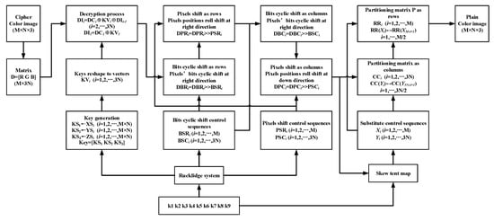
Figure 3.
The block diagram of the decryption scheme.
(1) Input a cipher image and the security keys into the decryption scheme. We assume the size of the inputted cipher image is M × N × 3. Then the encryption process begins.
(2) Change the inputted image from a 3D matrix into a 2D matrix, and denote it as D.
where Red, Green, and Blue are color components. D is an M × 3N matrix.
(3) The initial conditions of the Rucklidge system are generated using Equations (28)–(30).
(4) Under the initial conditions generated in Step 3, iterate Equation (2) through a 0.002 step size 4th-order Runge–Kutta method. There are three sequences gained from this iteration. Discard the first 800 iterations to eliminate the transitional state, and denote the sequences as XS, YS, and ZS, respectively.
(5) Generate key sequences from the iteration sequences generated in the previous step using Equations (31)–(34).
(6) Partition KEY into 3N vectors with M elements, and denote them as. Then, partition the matrix D generated from Step 2 into column vectors, and denote them as, where.
(7) Decrypt column vectors as in Equation (35).
(8) From the iteration sequences generated in Step 4, generate rows’ and columns’ pixel-level roll shifting control sequences using Equations (36) and (37), respectively.
(9) Generate rows’ and columns’ bit-level cyclic shifting control sequences using Equations (38) and (39), respectively.
(10) Repartition the matrix generated from Step 7 into row vectors, and denote them as . Then, cyclic shift all elements in the row vector to the right direction under the control sequence as in Equation (40).
(11) Denote the new row vectors generated in the previous step as . Then, roll shift the pixels position as in Equation (41).
where i = 1, 2, …, M, and j = 1, 2, …, 3N.
(12) Partition the matrix generated in the previous step into column vectors and denote them as . Then, cyclic shift all elements in the column vector to the right direction under the control sequence as in Equation (42).
(13) Denote the new column vectors generated in the previous step as . Then, roll shift the pixels position as in Equation (43).
where i = 1, 2, …, 3N, and j = 1, 2, …, M.
(14) Add all values of matrix DP generated in the previous step, and denote the summation as SUM.
(15) The system parameter and initial condition of the skew tent map are generated using Equations (45) and (46), respectively.
(16) Iterate Equation (1) under the system parameter and initial condition generated in Step 15, and denote the iteration sequence (without the first 200 iterations) as T. Take the first M elements of T to generate a new sequence X1 as in Equation (47). Then, take the repeated numbers away from X1, and append the absent elements to the end for generating the rows’ substitute control sequence X. In the same way, take the M + 1 to M + 3N elements to generate a new sequence Y1 as in Equation (48). Then, take the repeated numbers from Y1 and append the absent elements to the end for generating the columns’ substitute control sequence Y.
(17) Partition matrix DP generated in Step 13 into column vectors, and denote them as , where t = 1, 2, …, 3N. Substitute the column vectors under Y sequence controlling as in Equation (49).
(18) Repartition the column substituted matrix into row vectors, and denote them as , where t = 1, 2, …, M. Substitute the row vectors under X sequence controlling as in Equation (50).
(19) Reshape the result of Step 18 into an M × N × 3 matrix. Output the plain image, and the decryption process is finished.
3. Simulation and Security Analysis
Our proposed scheme is evaluated by software simulation in this section, and the software environment was MATLAB 2015b in MacOS High Sierra (10.13.1). The system parameters of the Rucklidge system, given by Equation (2), were a = 2 and b = 7.7, and the security inputted keys were k1 = 0.596345821685246, k2 = 0.521468245214562, k3 = 0.987412563548541, k4 = 0.536958542152365, k5 = 0.987452153255425, k6 = 0.665489221351221, k7 = 0.145851325412545, k8 = 0.325632541251254, and k9 = 0.285696325412524. The test images were 512 × 512 × 3-pixel RGB color images, and the simulation results are shown in Figure 4. Furthermore, many commonly used security analyses are given in the following subsections.
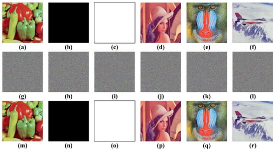
Figure 4.
Encryption results. (a–f) The plain images of ‘pepper’, ‘whole black’, ‘whole white’, ‘Lena’, ‘baboon’, and ‘airplane’. (g–l) The corresponding cipher images. (m–r) The corresponding recovery images by decryption.
3.1. Key Space Analysis
In our proposed scheme, the chaotic parameter and initial data are generated by the nine input keys k1,…, k9; therefore, the real keys of our proposed image encryption algorithm are those chaotic parameters and initial data. There are a chaotic parameter and initial data of the skew tent map, and three initial data , , and for the Rucklidge system. If we suppose that the change step of keys is, which is limited by computer accuracy, then the key space can be calculated as . For a cryptosystem to resist the brute-force attack, the key space needs to be at least [2,19]. Therefore, our proposed cryptosystem has a large enough key space to resist the brute-force attack.
3.2. Differential Attack
The plaintext sensitivity is an indicator to show whether an image cryptosystem can resist a differential attack. We measure plaintext sensitivity by quantizing the difference between images that are generated by encrypting two plain images with a one-bit difference. There are two indictors to measure the difference between images: number of pixels change rate (NPCR) and unified average changing intensity (UACI) [9,10,11,12,13].
NPCR and UACI are given by:
where and are cipher images that are generated from two plain-images that have only a one-pixel difference. M and N are the height and width of each image color component, respectively.
We obtain a new image by changing the one-bit pixel value in any one color component of the plain image, and then encrypt these two images. The NPCR reflects the percentage of different values of two pixels, which are selected in the same location and same color component of two cipher images. The UACI is the average intensity of the difference between two pixels which are in the same position of two cipher images.
In this section, we randomly change the one-bit value of a pixel in any one color component, and then calculate NPCR and UACI in the red, green, and blue color components, separately. The NPCR and UACI results are shown in Table 1. According to the results of the NPCR and UACI, our proposed cryptosystem has enough plaintext sensitivity to resist the differential attack.

Table 1.
The results of number of pixels change rate (NPCR) and unified average changing intensity (UACI).
3.3. Statistical Analysis
3.3.1. Histogram Analysis
It is important to ensure that the cipher image shows the uniform distribution in histogram analysis, or it is not able to resist the statistical attack. In this section, we test three group histograms: histograms of image pepper, whole black image, whole white image, and their corresponding cipher images. The test results are shown in Figure 5. The histogram analysis results showed that the proposed cryptosystem has an outstanding diffusion property and statistical attack resistance.
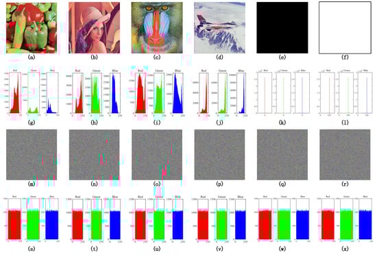
Figure 5.
Histograms. (a–f) The plain images of pepper, whole black, whole white, Lena, baboon, and airplane. (g–l) The corresponding histograms of those plain images. (m–r) The corresponding cipher images generated from encryption. (s–x) The corresponding histograms of those cipher images.
3.3.2. Correlation Coefficient
The correlation coefficient of adjacent pixels in the cipher image is an important indictor to judge the performance of an image encryption scheme. Adjacent pixels in a plain image always have a strong correlation; therefore, image encryption processes must destroy this correlation [14,15,16].
The correlation coefficient is given by:
where a and b represent color values of adjacent pixels, and
In this test, 10,000 pairs of adjacent pixels were randomly selected in the cipher image. Table 2 shows the results of the correlation coefficient calculation, and Figure 6 shows the distribution of pepper.
Table 2.
Correlation coefficients.
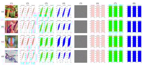
Figure 6.
Correlation distributions. (a–d) The data of pepper, Lena, baboon, and airplane, respectively. Column (1) is plain images. Columns (2)–(4) are the distributions of the plain images. Column (5) is the corresponding cipher image. Columns (6)–(8) are the distributions of cipher images. Columns (2) and (6) are the red component, columns (3) and (7) are the green component, and columns (4) and (8) are the blue component.
3.4. Key Sensitivity Analysis
An image cryptosystem requires a good key sensitivity to ensure the key and plaintext are fully confused. There are nine security keys in our scheme, and the change step of each key is . In this section, we encrypt the plain-image pepper by some keys that only change , and calculate the NPCR and UACI to assess the difference between ciphers. Therefore, we encrypt the plain-image pepper using the keys, which were assigned at the beginning of Section 3, and we denote the cipher image as C1. We then encrypt the plain-image pepper two times with the modified keys and , and we denote the two generated ciphers as C2 and C3, respectively. The test results are shown in Figure 7, and the NPCR and UACI between ciphers generated by different keys are shown in Table 3. The results clearly show that the proposed image cryptosystem has enough key sensitivity and has an exhaustive attack resistance.
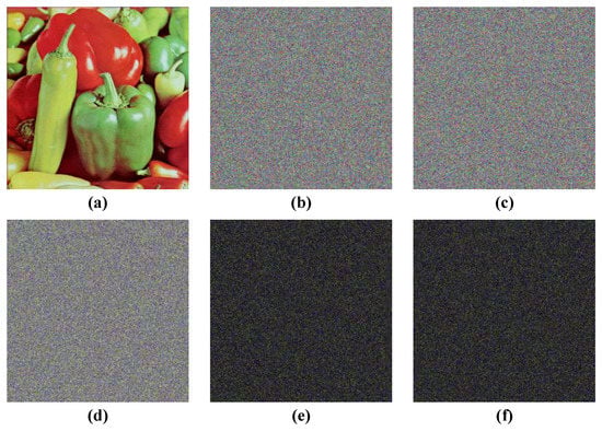
Figure 7.
Key sensitivity analysis. (a) Original image, (b) cipher image C1, (c) cipher image C2, (d) cipher image C3, (e) image of |C1-C2|, and (f) image of |C1–C3|.
Table 3.
Results of NPCR and UACI between ciphers.
3.5. Information Entropy Analysis
Here, we use the information entropy to indicate the uncertainty degree of a cipher image [9,22], and the information entropy is calculated by:
where L is the bit depth of each color component of the image, e.g., L = 8 for one color component of a 24-bit RGB color image, and is the probability of. The ideal information entropy of an 8-bit color component is bits. The entropy test of each color component is shown in Table 4. According to the test results, our entropies of each color component were close to 8, which is the ideal case for an 8-bit image. Therefore, this cryptosystem performs well for resisting an entropy attack.
Table 4.
The entropy test of each color component.
3.6. Speed Analysis and Comparisons
All of the simulations and tests in this paper were implemented in MATLAB R2015b on a MacBook with Intel® Core i7, CPU 1.4GHz, and 16GB memory, and the software was run on macOS. The speed analysis results are shown in Table 5, and the comparison with others are shown in Table 6. From tests and comparisons, our method has good encryption speed performance.
Table 5.
Speed test results.
Table 6.
Speed comparisons.
4. Conclusions
In this paper, we proposed an efficiency and secure color image encryption scheme based on a chaotic system. The proposed cryptosystem contains two parts: bit-level permutation and diffusion. The bit-level permutation algorithm contains three parts: A plain-image related rows and columns substitution, a pixel-level roll shift part, and a bit-level cyclic shift part. In the plain-related rows and columns substitution part, we involved the plain-image information to generate a control sequence by using a skew tent system. This part ensures that the correlation between the three color-components is broken, and our cryptosystem has enough plain-image sensitivity to resist the differential attack. In the pixel-level roll shift part and bit-level cyclic shift part, we produced a fully bit-level permutation controlled by two sequences using a Rucklidge system. In this paper, we considered the correlation between the three color-components; thus, we processed the three color-components simultaneously, and not individually, in permutation and diffusion. Finally, the results of the security analyses and comparisons showed that our proposed scheme not only has good security performance, but also has a speed advantage compared to other works.
Author Contributions
Formal analysis, Z.L.; funding acquisition, C.P.; investigation, Z.L.; methodology, Z.L.; project administration, C.P.; software, W.T. and L.L.; writing—original draft preparation, Z.L.; writing—review and editing, C.P., W.T., and L.L. All authors have read and agreed to the published version of the manuscript.
Funding
This research received no external funding.
Acknowledgments
Our research is supported by the National Natural Science Foundation of China (U1836205, 61662009, and 61772008), the open Foundation of Guizhou Provincial Key Laboratory of Public Big Data (2017BDKFJJ023 and 2017BDKFJJ026), the Science and Technology Foundation of Guizhou (Guizhou Science-Contract-Major-Program [2018]3001, Guizhou-Science-Contract-Major-Program [2018]3007, Guizhou-Science-Contract-Major-Program [2017]3002, Guizhou-Science-Contract-Support [2019]2004, Guizhou-Science-Contract-Support [2018]2162, Guizhou-Science-Contract-Support [2018]2159, Guizhou-Science-Contract [2017]1045, Guizhou-Science-Contract [2019]1049), and Scientific Research Foundation of Guizhou province, China (Grant No. QKHPTRC[2017]5788). The Project of Innovative Group in Guizhou Education Department ([2013]09).
Conflicts of Interest
The authors declare that they have no conflict of interest.
References
- Luo, Y.; Cao, L.; Qiu, S.; Lin, H.; Harkin, J.; Liu, J. A chaotic map-control-based and the plain image-related cryptosystem. Nonlinear Dyn. 2015, 83, 2293–2310. [Google Scholar] [CrossRef]
- Özkaynak, F. Brief review on application of nonlinear dynamics in image encryption. Nonlinear Dyn. 2018, 92, 305–313. [Google Scholar] [CrossRef]
- Patidar, V.; Pareek, N.; Sud, K. A new substitution–diffusion based image cipher using chaotic standard and logistic maps. Commun. Nonlinear Sci. Numer. Simul. 2009, 14, 3056–3075. [Google Scholar] [CrossRef]
- Shannon, C.E. Communication theory of secrecy systems*. Bell Syst. Tech. J. 1949, 28, 656–715. [Google Scholar] [CrossRef]
- Lorenz, E. Deterministic non-period flow. J. Atmos. Sci. 1963, 20, 130–141. [Google Scholar] [CrossRef]
- Matthews, R. On the derivation of a “chaotic” encryption algorithm. Cryptologia 1989, 13, 29–42. [Google Scholar] [CrossRef]
- Lee, W.K.; Phan, R.C.-W.; Yap, W.-S.; Goi, B.-M. Spring: A novel parallel chaos-based image encryption scheme. Nonlinear Dyn. 2018, 92, 575–593. [Google Scholar] [CrossRef]
- Ullah, A.; Jamal, S.S.; Shah, T. A novel scheme for image encryption using substitution box and chaotic system. Nonlinear Dyn. 2017, 91, 359–370. [Google Scholar] [CrossRef]
- Devaraj, P.; Kavitha, C. An image encryption scheme using dynamic S-boxes. Nonlinear Dyn. 2016, 86, 927–940. [Google Scholar] [CrossRef]
- Guesmi, R.; Ben Farah, M.A.; Kachouri, A.; Samet, M. A novel chaos-based image encryption using DNA sequence operation and Secure Hash Algorithm SHA-2. Nonlinear Dyn. 2015, 83, 1123–1136. [Google Scholar] [CrossRef]
- Hu, G.; Xiao, D.; Zhang, Y.; Xiang, T. An efficient chaotic image cipher with dynamic lookup table driven bit-level permutation strategy. Nonlinear Dyn. 2016, 87, 1359–1375. [Google Scholar] [CrossRef]
- Hu, T.; Ouyang, C.-J.; Liu, Y.; Gong, L.-H. An image encryption scheme combining chaos with cycle operation for DNA sequences. Nonlinear Dyn. 2016, 87, 51–66. [Google Scholar] [CrossRef]
- Li, C.; Luo, G.; Qin, K.; Li, C. An image encryption scheme based on chaotic tent map. Nonlinear Dyn. 2016, 87, 127–133. [Google Scholar] [CrossRef]
- Souyah, A.; Faraoun, K.M. An image encryption scheme combining chaos-memory cellular automata and weighted histogram. Nonlinear Dyn. 2016, 86, 639–653. [Google Scholar] [CrossRef]
- Tong, X.; Zhang, M.; Wang, Z.; Ma, J. A joint color image encryption and compression scheme based on hyper-chaotic system. Nonlinear Dyn. 2016, 84, 2333–2356. [Google Scholar] [CrossRef]
- Wang, X.; Liu, C.; Xu, D.; Liu, C. Image encryption scheme using chaos and simulated annealing algorithm. Nonlinear Dyn. 2016, 84, 1417–1429. [Google Scholar] [CrossRef]
- Wang, X.; Liu, C.; Zhang, H. An effective and fast image encryption algorithm based on Chaos and interweaving of ranks. Nonlinear Dyn. 2016, 84, 1595–1607. [Google Scholar] [CrossRef]
- Bowley, J.; Rebollo-Neira, L. Sparsity and “something else”: An approach to encrypted image folding. IEEE Signal Process. Lett. 2011, 18, 189–192. [Google Scholar] [CrossRef][Green Version]
- Álvarez, G.; Li, S. Some basic cryptographic requirements for chaos-based cryptosystems. Int. J. Bifurc. Chaos 2006, 16, 2129–2151. [Google Scholar] [CrossRef]
- Li, Z.; Peng, C.; Li, L.; Zhu, X. A novel plaintext-related image encryption scheme using hyper-chaotic system. Nonlinear Dyn. 2018, 94, 1319–1333. [Google Scholar] [CrossRef]
- Zhu, H.; Zhang, X.; Yu, H.; Zhao, C.; Zhu, Z. An image encryption algorithm based on compound homogeneous hyper-chaotic system. Nonlinear Dyn. 2017, 89, 61–79. [Google Scholar] [CrossRef]
- Ye, H.-S.; Zhou, N.-R.; Gong, L.-H. Multi-image compression-encryption scheme based on quaternion discrete fractional Hartley transform and improved pixel adaptive diffusion. Signal Process. 2020, 175, 107652. [Google Scholar] [CrossRef]
- Zhu, L.; Song, H.; Zhang, X.; Yan, M.; Zhang, T.; Wang, X.; Xu, J. A robust meaningful image encryption scheme based on block compressive sensing and SVD embedding. Signal Process. 2020, 175, 107629. [Google Scholar] [CrossRef]
- Joshi, A.B.; Kumar, D.; Gaffar, A.; Mishra, D.C. Triple color image encryption based on 2D multiple parameter fractional discrete Fourier transform and 3D Arnold transform. Opt. Lasers Eng. 2020, 133, 106139. [Google Scholar] [CrossRef]
- You, L.; Yang, E.; Wang, G. A novel parallel image encryption algorithm based on hybrid chaotic maps with OpenCL implementation. Soft Comput. 2020, 24, 1–15. [Google Scholar] [CrossRef]
- Ouyang, D.; Shao, J.; Jiang, H.; Nguang, S.K.; Shen, H.T. Impulsive synchronization of coupled delayed neural networks with actuator saturation and its application to image encryption. Neural Netw. 2020, 128, 158–171. [Google Scholar] [CrossRef]
- Wen, W.; Hong, Y.; Fang, Y.; Li, M.; Li, M. A visually secure image encryption scheme based on semi-tensor product compressed sensing. Signal Process. 2020, 173, 107580. [Google Scholar] [CrossRef]
- Ye, G.; Pan, C.; Dong, Y.; Shi, Y.; Huang, X. Image encryption and hiding algorithm based on compressive sensing and random numbers insertion. Signal Process. 2020, 172, 107563. [Google Scholar] [CrossRef]
- Zhang, Y.; Chen, A.; Tang, Y.; Dang, J.; Wang, G. Plaintext-related image encryption algorithm based on perceptron-like network. Inf. Sci. 2020, 526, 180–202. [Google Scholar] [CrossRef]
- Zhang, Y.-Q.; He, Y.; Li, P.; Wang, X.-Y. A new color image encryption scheme based on 2DNLCML system and genetic operations. Opt. Lasers Eng. 2020, 128, 106040. [Google Scholar] [CrossRef]
- Arpacı, B.; Kurt, E.; Çelik, K. A new algorithm for the colored image encryption via the modified Chua’s circuit. Eng. Sci. Technol. Int. J. 2020, 23, 595–604. [Google Scholar] [CrossRef]
- Wen, W.; Wei, K.; Zhang, Y.; Fang, Y.; Li, M. Colour light field image encryption based on DNA sequences and chaotic systems. Nonlinear Dyn. 2019, 99, 1587–1600. [Google Scholar] [CrossRef]
- Khan, F.A.; Ahmed, J.; Khan, J.S.; Ahmad, J.; Khan, M.A. A novel image encryption based on Lorenz equation, Gingerbreadman chaotic map and S8 permutation. J. Intell. Fuzzy Syst. 2017, 33, 3753–3765. [Google Scholar] [CrossRef]
- Xiang, T.; Liao, X.; Wong, K.-W. An improved particle swarm optimization algorithm combined with piecewise linear chaotic map. Appl. Math. Comput. 2007, 190, 1637–1645. [Google Scholar] [CrossRef]
- Rucklidge, A.M. Chaos in models of double convection. J. Fluid Mech. 1992, 237, 209–229. [Google Scholar] [CrossRef]


© 2020 by the authors. Licensee MDPI, Basel, Switzerland. This article is an open access article distributed under the terms and conditions of the Creative Commons Attribution (CC BY) license (http://creativecommons.org/licenses/by/4.0/).