1. Introduction
Multirobot cooperation as the swarm system is one of the most discussed topics in the field of Robotics. Multirobot symmetry pattern formation helps robots to implement tasks together. The numerous applications can open up in terms of surveillance, inspection, maintenance, and rescue. Multirobot systems (MRS) include a group of multiple robots with the same characteristics operating in a shared, and symmetrically formed workspace [
1]. This concept covers the examples of robotic arms, humanoid robots, ground and aerial mobile systems, and autonomous vehicles. The MRS term can be defined as multiagent systems, robotic swarms, or sensor networks in the literature.
Many robotic applications are focused on carrying out tasks in an unknown environment that would require different perception or sensing abilities. Even after the robot is equipped with multiple arrays of sensors, in these environments, there can be sensory blind spots that might trigger a failure mode within the robot. If the robot does not have the contingency to identify this sensory blind spot in time, there might be an accident involving the robot causing injury to living things or structural damage to the surroundings and the robot itself. One of the swarm robot methodologies is primarily used in situations where the environment is unknown. Mapping an unknown environment is dangerous pertaining to the losses or damages that can cause the system’s failure. To avoid this, the robots set out to map the unknown area with precision by still considering the dangers lurking in the forms of uneven terrains, glass walls, steep slopes, among others. The information gathered by all the swarm robots will help in learning collectively about the characteristics of the environment, thus preventing any damages to the robots or the environment. These swarm robots can be expanded to applications such as surveillance as mentioned by the authors in [
2]. In the paper, a self-reconfigurable robot that can crawl, climb, and roll in any terrain was presented. This kind of robot assists in opening up new doors in the field of surveillance and inspection. Multiple robots of the same kind can be deployed into areas with a high degree of uncertainty.
These swarm robots usually are inspired by nature. Swarms of insects can be observed to understand swarming techniques, later adapted to different robotic scenarios. Some of such famous algorithms are ant colony optimization (ACO) [
3], the bees algorithm (BA) [
4], and glow-worm swarm optimization (GSO), among others. These swarm algorithms can be used for many applications, as mentioned earlier. One such interesting application is to search for a target object within a given unknown environment. The authors in the paper [
5] proposed a decentralized control algorithm that enables the swarm robots to search for a given target. This method was inspired by bacteria chemotaxis. In order to search for a target, the robots have to visit every place in a given area. This can be rather termed as an area coverage problem. Numerous literature works addressed this area coverage issue using single robots [
6,
7], self-reconfigurable robots [
8,
9,
10], and swarm robots [
11]. Even with the area coverage problem, it is important to have a controller to enable the swarm robots to localize themselves relatively and move in a shape.
Research is being carried out in certain aspects, such as shape formation within the swarm structure. It will not be easy to enable all the swarming robots to form inside complex shapes without proper algorithms. The authors in [
12] utilized a bioinspired morphology change approach that can be applied to the multirobot control algorithm to achieve the complex shape. In another example, the authors [
13] proposed a control technique that enables a swarm of satellites to assemble in a hexagonal symmetrical lattice shape. There are several such examples [
14,
15,
16] that showcases the control strategies that can be adapted to achieve different topology symmetrical shapes. Having different topology shapes is necessary in some situations. Let us consider the surveillance situation, where the intended application tracks a given object of interest in an unknown area. In this scenario, instead of sending the robots randomly in different directions, it will be safe to arrange the robots in a given defensive shape to perform the area coverage task. In this way, the risk to the robots from external threats would be reduced, and any knowledge gained through such collective learning can be easily applied to the whole group.
There is another important aspect of overcoming the challenge of control and coordination. In the cases of multirobot setups, the control and coordination strategies usually boil down to four categories: virtual structure algorithms, leader–follower algorithms, artificial potential field (APF) algorithms, and bioinspired algorithms. The virtual structure algorithms are the primitive algorithms that regard the robot as a single structure and establish all the algorithms that are originally developed for single robots [
17,
18,
19]. In the second category, leader–follower algorithms consist of a leader, and the other robots follow the leader. Their locations are estimated relatively with each other. Here, most of the intelligent operations are performed on a single robot, the leader robot, and the other robots will follow it. There are several implementations done by various researchers for various applications [
20,
21,
22]. The current paper utilizes the leader–follower approach where the master robot runs the intelligent operations while the slave robots follow it. In the third category, APF algorithms are implemented for real-time path planning of the robots addressing the obstacle avoidance situations [
23]. It is a distributed control model where the goal is considered to attract while the obstacle tends to repel. There are certain challenges with this as well, such as getting stuck in local minima. However, there are various literature works addressing this issue [
24].
In the last set of algorithms, bioinspired algorithms are inspired by the flocking patterns of the insects. Many path planning strategies have been proposed based on this concept. The authors in [
25] presented a cooperative and a distributive navigation strategy for a multirobot system. Even though with limited communication capabilities, the robots could find and decide the paths to reach the goal points efficiently. An artificial pheromone is utilized to mark the areas that are visited by the other robots. This is done to prevent revisiting the areas in order to find the path. Another group of authors in [
26] mimicked biological neural systems to perform task assignments to swarm robots. This approach can handle dynamic path planning in 3D environments that are prone to uncertainty. The authors in [
27] presented an algorithm that can produce an optimal path for multirobot groups. As proposed in the algorithm, the scout ants searched for the grid randomly without employing the pheromones. This algorithm utilizes two types of ants: one searching from the home position to the destination, while the other searching from the destination to the home position, thus, becoming into a bidirectional search. The grid places visited by these ants will be stored to avoid future repetition. Another group of authors in [
28] proposed two extensions of the Particle Swarm Optimization (PSO) and Darwinian Particle Swarm Optimization (DPSO) as Robotic PSO (RPSO) and Robotic DPSO (RDPSO). These algorithms utilize bioinspired techniques while accounting for obstacle avoidance. They utilize social inclusion and exclusion concepts, analogous to reward–punish, to perform the estimation away from the local minima. The authors in the [
29] presented an implementation of the previously mentioned Robotic Darwinian Particle Swarm Optimization (RDPSO) algorithm for a search and rescue application. They reiterated that this approach helps solve the local minimum problem by adopting a Darwinian approach suitable for search and rescue applications. There are also other applications where the evolutionary algorithms can be used.
The authors of [
30] used the differential evolution to update the control parameters, without the need of a model, for multirotor applications. Their research was aimed to address the problems aroused in the flight performance due to the possible reasons of rotor hardware degradation and weight distribution due to extra payload among others. The evolution of the controllers based on the given requirement can replace the traditional approach of manually tuning the control parameters. The authors of another paper [
31] proposed Hyb-CCEA. It is a cooperative coevolutionary algorithm that is meant to handle situations that involves heterogeneous multiagent systems. Their approach can also help to converge suitable team compositions, in the case of homogeneous, heterogeneous or hybrid teams. Their approach can be used in the domains where the possible outcomes are unknown. In another work [
32], the authors analyzes the performance of the Brain Storm Optimization (BSO) and proposed an orthogonal learning framework to improve its learning mechanism. In regard to this, the authors proposed two Orthogonal Design (OD) engines that includes the exploration and exploitation. They are introduced to discover and utilize the relevant search experiences for performance improvements. The authors claim that the proposed approach can optimize complex functions.
With the increase in the complexity of the applications, the traditional algorithms might not be able to solve the optimization problem. The authors in [
33] proposed an approach to solve the large-scale multiobjective and many-objective optimization problems. The approach involves the optimization of decision variables using the adaptive strategy by embedding the guidance of reference vectors in the control variable analysis. The authors claimed to have validated the efficiency of the proposed approach on large-scale multiobjectives and many-objective optimization problems. Reinforcement learning approaches are also adopted to solve the optimization problems. The authors in the [
34], took an approach that leverages on the multiagent reinforcement learning approaches. The authors proposed a dynamic correlation matrix based multiagent reinforcement learning approach. The approach results in updating the metaparameters using the evolutionary algorithms. They claim that this method not only enables the agents to learn from the local experiences but also from the experiences gained by the other agents. In similar lines, the authors from the paper [
35] proposed an adaptive reference vector reinforcement learning approach to decomposition-based algorithms. The reinforcement learning handles the reference vector adaptation process, by leveraging on the environment feedback and choosing the optimal actions for convergence. Along with it, the reference point sampling utilizes the estimation-of-distribution learning models to sample new reference points.
The current paper utilizes a swarm of robots to address the problem of robot formation in unknown environments by low cost sensor fusion for robot self-localization and global path planning. Specifically, by following the master, multifollowers form symmetrical shapes as defined locations. The global path planning strategy enables the robots to reach the desired goal point while avoiding obstacles in their path. The master robot defines the path then leads the team of several robots to follow to desired locations. That framework reduces the complexity of the swarm system since the advance decision is processed at the master robot; the follower issues merely the midware commands from motor driver to actuators. The system is also deployed as service bots where robots transport particular payloads from one place to another as instructed by the operator.
The main contributions of the paper are summarized as follows:
The sensor fusion from the UWB position system, IMU, and wheel encoders for accurate localization in the unknown environment is validated on a low-cost and lightweight platform called the Falcon platform through a built-in GUI.
A control algorithm as global path planning incorporating the skid steering kinematic based path tracking for multiple robots in the swarm system with a master and followers. To this end, the integrator-based dynamic linearization decouples the dynamics in the 2D coordinate, then given the designed controller for the leader robot, the formation control problem boils down to choosing the desired trajectory for the follower robots.
Experiment results in both simulated and real-world experiments demonstrate that formation strategy for multiple robots by the proposed global path planning combined with the skid steering based control schematic.
The rest of the paper is organized as follows.
Section 2 presents the context of application.
Section 3 describes the system architecture.
Section 4 presents a sensor system for autonomy navigation in the unknown environment. In
Section 5, the proposed technique of mathematical model for multiagents control mechanism is given in detail.
Section 6 presents the results and discussion on the proposed method’s performance. Finally,
Section 7 is conclusions.
3. System Architecture
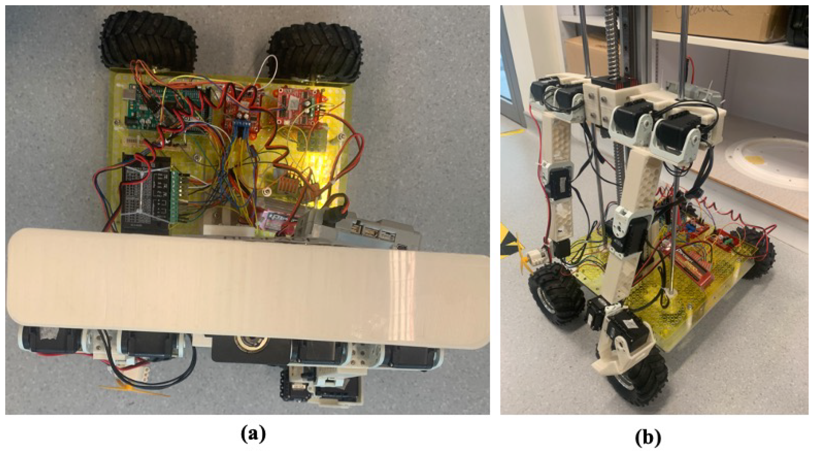
As the requirement as described in the context of application, we have designed the swarm system. The swarm system consists of the operator control center installed in the workstation and two classes of robots named Falcon stationary and Falcon mobile platforms. The robot’s mechanisms, electronics, and sensor components are shown in
Figure 1. One is the stationary platform that carries a stationary beacon as shown in
Figure 1a, and the other is a mobile platform that carries a mobile beacon as shown in
Figure 1b. The system architecture with ROS [
36] as the communication media for the main components, including an operator Console Unit, ROS master, the stationary platform, and the mobile platform, is shown in
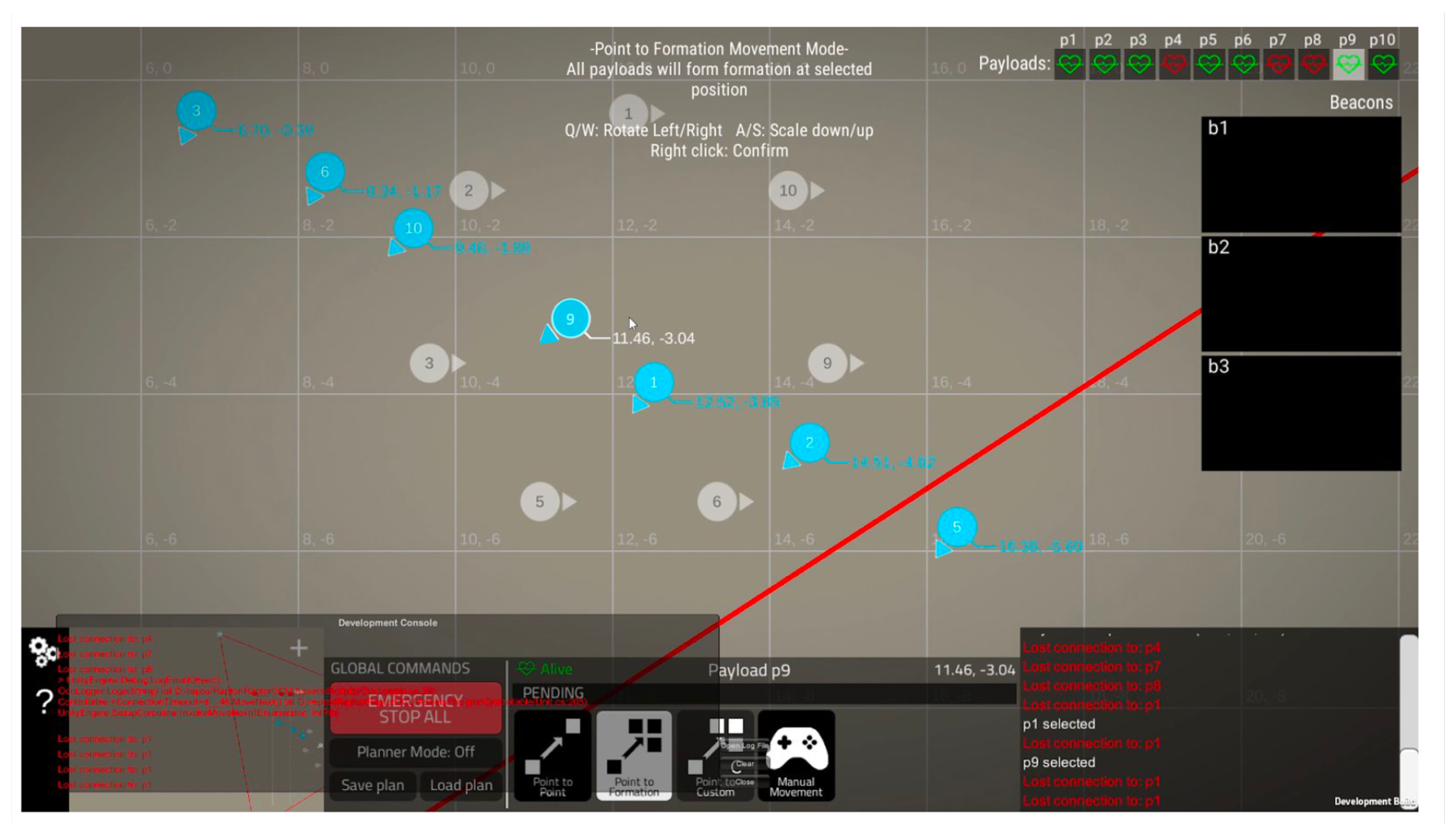
Figure 2. The stationery platforms provide the manual control mode for the operator to navigate them remotely to the desired location in the workspace to setup the workspace. The mobile platforms are set to form a group of up to ten units with one master and the others as followers inside the workspace to conduct the swarming tasks. ROS master is the central controller in which all information is received, processed, and sent. The operator’s Console Unit is designed as a graphical user interface for the operator to command platforms.
Falcon, a skid steering robot, carries lidar (only mobile beacon robot for obstacle avoidance) and IMU and UWB beacon to enable autonomous navigation with obstacle avoidance feature in the workspace. The dimensions of each robot are 10 × 40 × 40 cm, which weighs about 1.2 kg. The robots are 3D printed with a nylon material. They are four-wheel mobile skid steering robots. All wheels are made of rubber of the same size with a diameter of 10 cm. A microprocessor is placed on each robot, which is responsible for the actions performed by the robot. The microprocessor used is the raspberry pi 4 model to which all the electronic sensors and motors are connected. 12 V DC motors are used to drive the wheels. RoboClaw 2 × 7 A motor controllers are used. The feedback loop is implemented in the control unit using motor encoders to robot wheel odometry. Pololu MinIMU-9 v5 9-degree-of-freedom absolute IMU is used for calculating the heading angle during its navigation. IMU is interfaced with raspberry pi over the I2C bus. A Low-cost RPLidar A1 sensor is mounted on the top of the front side of the robot. By using laser scan and project on a local costmap, the Lidar aids in the process of obstacle avoidance during the robot traversal toward the goal location. This lidar is efficient and has the capability to measure obstacles up to 12 m range. The robots see each other as an obstacle and try to avoid collision while reaching its goal. A Marvelmind UWB with stationary and mobile versions are shown in
Figure 1 in which the beacons on top of the robots are connected to Raspberry Pi through a USB cable, which will enable the positioning of swarm robots in the 2D map. Among the mobile robots, the master robot is equipped with the Intel® Compute Stick, the advanced and lightweight CPU to program the planning tasks during the swarm actions.
4. Sensor System for Autonomy Navigation in the Unknown Environment
4.1. Workspace Setup with the UWB Positioning System
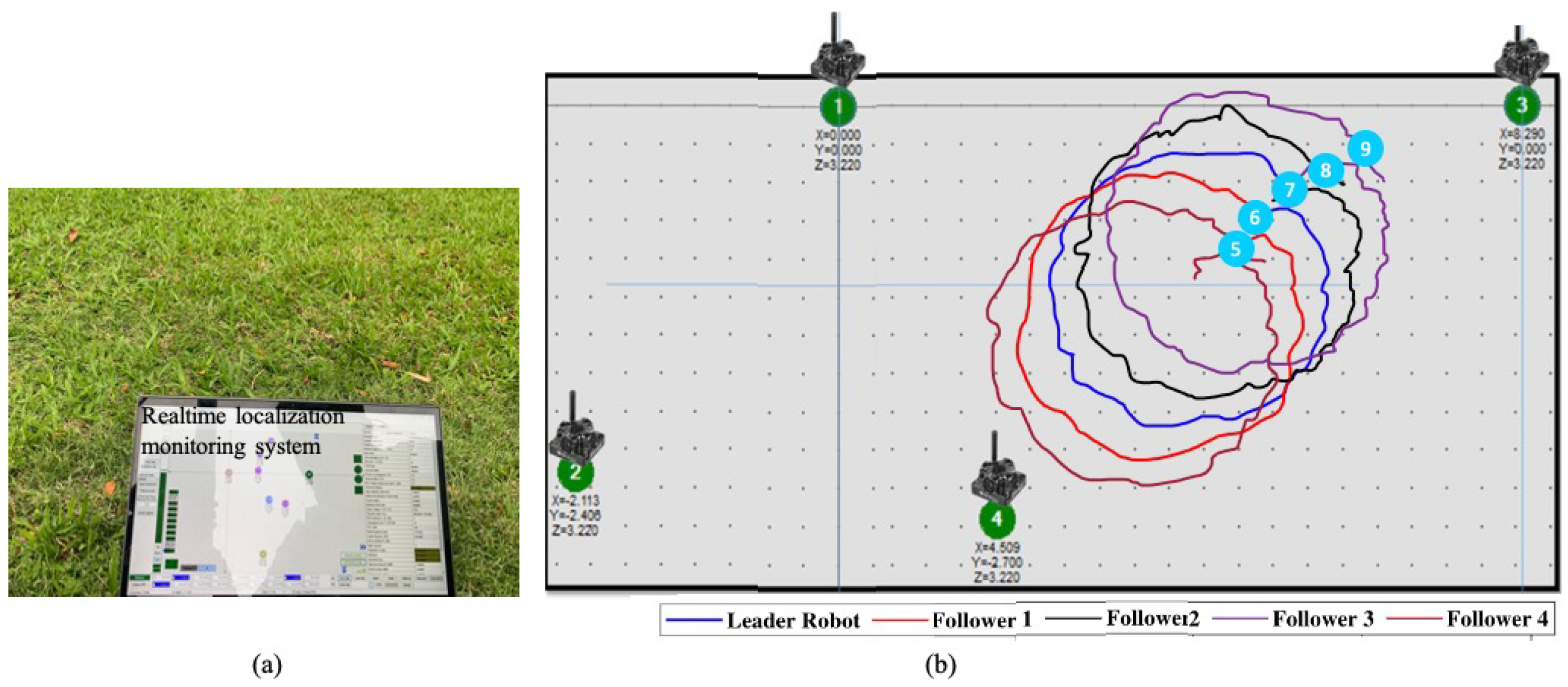
This section illustrates the system behavior on how the robots are localized. Note that localization consists of the location and yaw orientation. Generally, without the built 2D or 3D map, the robots use special modules like GPS and Inertial measurement units to facilitate localization during navigation. However, GPS modules such as real-time kinematic (RTK)-based technology are expensive, bulky, and require an open space to get the accuracy. Therefore, precise localization is only possible with the high-performance GPS modules, which is a menial task to integrate on every robot in our proposed swarm system.
The robots of the swarm system get the 3D position inside the deployed unknown-workspace using the UWB localization technique. UWB localization uses modules called static and mobile beacons to estimate the beacons mounted on the robots. The UWB beacon-based system provided a high precision of approximately cm inside the workspace defined by stationary beacons within the diameter of 50 m. To guarantee precise localization, the mobile beacons are mounted on top of the robots to assume a line of sight condition with at least three stationary beacons.
A workspace for the robot to operate is formed by deploying manually stationary robots to corners of the workspace, which is defined according to the user’s demands. At least three stationary beacons (generally with four beacons to ensure the redundancy backup in case of hardware failure as shown in the
Figure 3) are needed in this method. They can be far away from each other up to 30 m to form a triangle with the line of sight condition. After setting up the workspace as the boundary of stationary beacons, each robot in this workspace carrying a mobile beacon facilitates finding the accurate position concerning the map formed by the previous beacons workspace setup.
Moreover, it is critical that the coordinate axis in which the robot is localized should have reference to the orientation system provided by the IMU coordinate axis so that both can be related in the robot operation. In the next section, we discuss a sensor fusion method to localize, orient, and navigate a robot in an unknown map formed by a precision positioning ultrawideband (UWB) beacon-based system incorporating orientation system IMU and wheel odometry encoders. All of the robots are operated using the ROS (robotic operating system) framework over WiFi or a 4G communication network. The position topics sent by the stationary robot are available for all the robots in the system.
4.2. Initial Orientation Estimation
Since the UWB beacon system only provides the position in the 3D coordinate and relative orientation by IMU, we developed the method to estimate the transformation between frames to find the robot’s orientation in the beacon frame. The IMU data is not directly fused with the beacon data as their sensor values are in different reference frames. There is a need to find the transformation between frames to find the robot’s orientation in the beacon frame. In order to localize the robot, a novel method called Initial Orientation Estimation is proposed. This method finds the initial orientation angle of the robot in the beacon frame, and then the real-time orientation in the global frame is updated depending on the robot’s movement. This initial orientation estimation is the critical step for each Falcon in the robot workspace to localize itself properly.
The beacon coordinates axes’ orientation with respect to the ground frame depends on how the stationary beacons are deployed in the open space. As the deployment of the stationary beacons is arbitrary, there is no reference to the ground frame formed by the absolute IMU cardinal directions. A relation between these coordinate axes should exist for localization and navigation. To find this, a method to find the initial docking orientation of robots in beacon coordinate axes had been developed purely based on the coordinates generated by the beacon system.
4.2.1. Finding the Initial Orientation Angle
When deployed in the unknown environment, the stationary beacons are set randomly by the operator, i.e.,
Figure 3, the initial orientation angle is found solely using beacon generated coordinates with the help of primary slope and linear equations. After the system finishes booting up, the robot is initially moved forward for 3 s. During this process, the location as coordinate points, namely
A and
B generated by beacons, are recorded before and after robot forward motion. These two coordinate points are used in finding the robot heading in the beacon frame using the slope formed by two points
A and
B.
In
Figure 4a the
coordinate axes and cardinal directions represent the beacon frame and the IMU frame, respectively. However, these two frames may not be oriented in the same way, and let us consider that the beacon frame is
times rotated about geographical axes.
Initially, considering the robot is moved forward from point
A to
B, let A is
and
B is
, then slope of AB is given by Equation (
1). The initial orientation angle
of the robot with respect to the beacon frame can be derived as in Equation (
2).
4.2.2. Calculate the Offset Angle
Using the initial orientation angle and the yaw generated from the absolute IMU, the relation between the beacon frame and the IMU frame is calculated by finding the rotation angle between the frames. As denoted in the
Figure 4a, from the the value of
given by the IMU sensors real-time value,
can be calculated by the Equation (
3).
4.2.3. Heading Angle of Robot in Beacon Frame
After estimating the offset angle of the localization system, the robot’s heading while the moving arbitrarily is calculated in the UWB beacon frame. Specifically, considering the arrow with robot index represents the orientation of the robot in the
Figure 4b, the heading angle,
is calculated as in Equation (
4) by using the
from the previous step. Where
is the robot heading angle in the beacon frame,
is the robot heading angle given by the IMU sensor’s real-time value.
4.3. Sensor Fusion for Precise Localization
The IMU data is not directly fused with the beacon data as their sensor values are in different reference frames. There is a need to find the transformation between frames to find the robot’s orientation in the beacon frame. To enhance the self-localization in the unknown environment we use the sensor fusion technique.
The swarm robots are randomly deployed in the unknown environment and do not use the sensor such as lidar to build the map. To enable autonomous navigation and swarm, the individual agent of this robot system should continuously be updated with the information of both its and the team members’ locations consisting of the absolute orientation and position with respect to the reference global map.
The wheel odometry is fused with the yaw value of IMU to further refine the orientation of the robot odometry. The IMU data is not directly fused with the beacon data as their sensor values are in different reference frames. There is a need to find the transformation between frames to find the robot’s orientation in the beacon frame. The raw IMU values as raw pitch yaw fields is added to robot localization package which uses EKF [
37] to eliminate the sensor noise. To compensate for errors in the relative velocities between wheels which can affect robot trajectory, the feedback control is used to derive the left and right wheel velocities. The robot location, filtered by EKF, including the current position and heading in the global frame is the input for the control loop. The ROS based sensor fusion flow is shown in
Figure 5. This filtered odometry is then passed to the global and local path generators to execute the navigation in the UWB workspace.
5. Mathematical Model for Multiagents Control Mechanism
Using the proposed UWB and IMU-based self-localization system, the location of the developed robot in the global frame is well-defined. Based on the ROS network, the robot locations can be comprehended by the other members. To simplify the navigation task for multiple agents, we develop the master following in which all the slave robots will follow the one master path defined by the ROS move base package to maintain the required formation symmetrically. We consider a group of skid-steering four-wheel for our purpose to generate the appropriate motion command for robot.
Figure 6 represents the schematic of a conventional four wheel skid steering robot. The robot dynamics can be described by the robot coordinates
(planar position and steering). The variable
denotes the angle between the COG (
) and the wheels,
and
are the width and length of the robot. The relative position of the wheels are derived as in Equation (
5):
The robot is driven through reverse differential methodology, where the control inputs for the two inner and outer wheels are kept as same, i.e., as in Equation (
6),
where
are the velocity and steering inputs for the COG. The kinematics for the COG can be expressed as the unicycle model, described as in Equation (
7):
The kinematics for the
coordinate of the robot becomes as in Equation (
8):
which is singular and not controllable. This singularity problem can be avoided by exploiting an integrator
and modeled as in Equation (
9):
where
f is the linear acceleration. By differentiating again as in Equation (
10), one obtains
where the new input and the input matrix are given by
and
respectively. By using a control law as in Equation (
11)
(
10) is converted into a decoupled linear system as in Equation (
12)
where
can be chosen as the control input, and separate PID like feedback for
can be chosen for tracking any desired trajectory (
).
The above control law assumes that the measurements for are available and accurate. As this is not the case in many practical applications, the control law should deal with it.
5.1. Robust Control Law
Sometimes, different uncertainties such as inaccuracies in the measurement of
or external disturbances creep into the mathematical model. The control law should be chosen to mitigate such issues. For (
10), a control law can be chosen as in Equation (
13):
where
can be selected as two separate PD feedback, whereas
represents the robust part. The uncertain linearized system can be expressed as in Equation (
14):
where the uncertainties are lumped in the terms
and
. For the design, assume the existence of two constants
, which satisfies conditions as in Equation (
15)
we select two sliding surfaces designed as in Equation (
16):
where
, and
. The velocity and acceleration are defined as in Equation (
18), and Equation (
17), respectively
For
(
is a positive scalar), the acceleration as in Equation (
19),
If
, then the acceleration as as in Equation (
20)
From Lyapunov [
38] direct method, it can be concluded that
, and can be presented as in Equation (
21)
The convergence of
can be inferred similarly. The overall control law for the robot is given by Equation (
22)
To avoid singularity, one can pick , which prohibits v from crossing zero.
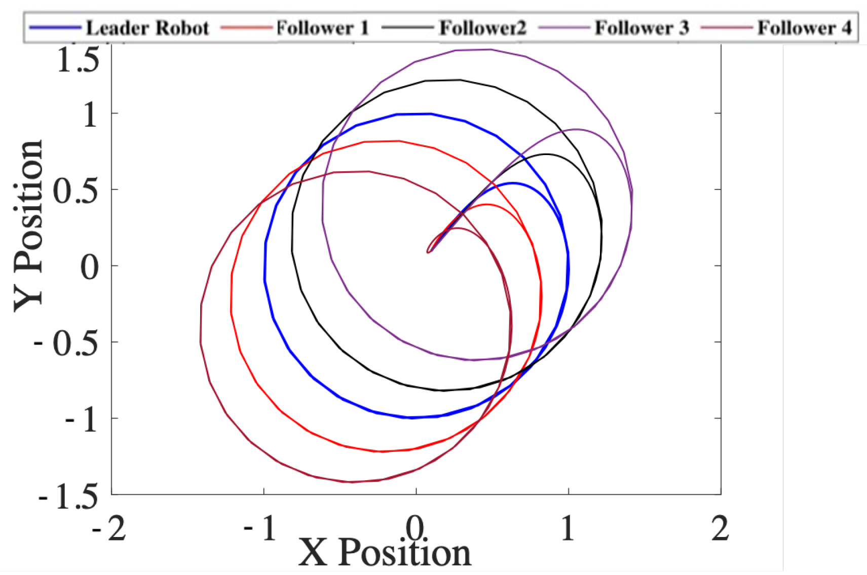
5.2. Leader Follower Formation Control
The integrator-based dynamic linearization decouples the dynamics in the
x- and
y-directions. Given that the controller for the leader robot is designed according to the method given in the previous section, and the formation control problem boils down to choosing the desired trajectory for the follower robots. Let us represent the leader position at any instance as
. For the follower robots, the desired trajectories (
) can be chosen as in Equation (
23)
where
are constant representing the desired separation in the respective coordinate. These constants can also be chosen as time varying quantities, which can assure time varying formation tracking. we define the error variables and the sliding surfaces for followers as in Equation (
24):
The control law for the followers can be selected as as in Equation (
25):


 ,
, 


