Article

Comparison Study on the Performance of a Novel and Traditional Energy Piles by Laboratory Tests

1
Key Lab of Coastal Urban Resilient Infrastructure, Ministry of Education (MOE), Shenzhen 518060, China
2
College of Civil and Transportation Engineering, Shenzhen University, Shenzhen 518060, China
*
Author to whom correspondence should be addressed.
Symmetry 2021, 13(10), 1958; https://doi.org/10.3390/sym13101958
Submission received: 29 August 2021 / Revised: 6 October 2021 / Accepted: 8 October 2021 / Published: 18 October 2021

Abstract

:
Phase change material (PCM) is a substance that can absorb or release sufficient latent heat at phase transition. By encapsulating phase change paraffin in hollow steel balls in the concrete, an energy pile with PCM was innovatively produced to improve energy efficiency for the ground heat pumping system. Laboratory tests were carried out on both PCM energy pile and traditional concrete pile to evaluate the thermo mechanical performance. Two piles were heated and cooled through inside tubes at a constant flow rate. The laboratory tests on the two piles were symmetrical for the two horizontal directions in geometry, and heat transfer process follows conservation laws of energy. The temperature response of the pile and soil, internal strain, pile displacement, pore pressure, and soil pressure under heating-cooling cycles were examined. Compared with the traditional concrete pile, the PCM energy pile can effectively reduce the surrounding soil temperature. The use of PCM in the pile can improve the capacity of heat storage and make the pile more effective in heat exchange. Non-uniform thermal strain and accumulations of heat and irrecoverable displacement were observed in the repeated heating-cooling process. The study can provide references for the practical implication of PCM energy piles.

1. Introduction

The relationship between energy utilization and underground space is becoming intense because of urbanization growth in recent years [1]. Since piles are widely used in underground space as foundations, support structures of excavation, and foundations to restrain settlement of tunnel station [2], researchers have proposed a new type of heat transfer technology by burring tubes in piles, also known as energy pile or heat exchange pile. Compared with traditional piles, energy piles can provide structural support and heat transfer to soil. Therefore, energy piles as a heat transfer intermediary, more attention needs to be paid on the coupled thermal and mechanical behaviors of energy piles to evaluate the impact of the additional thermal loads. Moreover, the soil-pile interaction under thermal loads should be examined.
Due to the complexity of the operation of energy piles, experiments have usually been adopted for the investigation on the thermo-mechanical behaviors of energy piles with surrounding soil. At present, many experimental results on energy piles, including in situ tests and laboratory tests, have been reported. Through in situ tests, the mechanical behavior and heat transfer performance of energy piles loaded by heating in field was investigated [3]. An energy pile in situ observation on the development of axial stress caused by temperature change was also conducted [4]. The results of the two in situ tests were compared comprehensively and the transfer mechanism of heat transfer was simplified [5]. In addition, the creep deformation of energy piles caused by temperature through in situ thermal tests on an energy pile buried in clay soil was reported [6]. From these studies, it could be concluded that the temperature variations had brought out internal stress and irrecoverable deformation of the energy piles that could not be neglected. On the other hand, thermal conductivity and heat transfer was also examined and better economy and easier installation types of energy piles were suggested [7,8,9,10].
Because of the limitations of the in situ tests, many laboratory studies were also carried out in model scale [11,12,13,14,15,16,17]. The thermo-mechanical behaviors, displacement changes, and heat transfer efficiency of energy piles under cyclic heating or cooling load could be examined. It is important to understand or even control the performance of energy piles for the long-term and safe use of geothermal energy, but at present, related studies in this regard are still insufficient. The transient thermo-mechanical response of the energy piles during heating-cooling cycles through centrifugal tests was investigated and the soil-structure interaction behavior has been clarified [11]. Centrifugal tests were also carried out to study the effect of over-consolidation degree on settlement of energy piles in clay during heating-cooling cycles and the results revealed that the soil condition was an important influence factor when using energy piles [12]. In a previous study, laboratory tests were carried out to investigate the thermal response of an ordinary concrete pile in saturated soil [18]. Nevertheless, the temperature change, thermal stress inside pile, and the side friction on pile-soil contact surface were not investigated.
Through the reported literature, most studies have mainly focused on the heat transfer or displacement and axial stress of piles. Especially in laboratory tests, small-diameter metal pipe piles were used, and the conditions of interface contact and soil-pile interaction are different from those conditions of large section concrete piles in field engineering. Additionally, the long-term thermal loading that may cause cracking or degradation of concrete pile has not been considered, which would affect the structural performance of large section concrete piles. Therefore, from a practical engineering perspective, the thermo-mechanical behaviors of energy piles are not well understood. As non-uniform temperature distribution in the pile body will occur due to the arrangement of the buried heat exchange tubes, this non-uniform temperature distribution may cause uneven thermal strain and stress in energy piles, resulting in cracking of the pile body. In particular, under the conditions producing contractive stress and strain in piles [19], large settlements will occur. However, the research on this aspect has received less attention.
For practical application, how to use underground space resources more effectively and improve energy efficiency are also worthy of attention. Phase change material (PCM) is a substance that can storage or release heat by phase change. It has the characteristics of high phase change latent heat and small temperature fluctuations. Although phase change materials (PCMs) cannot generate any form of energy by themselves, the phase transition process can realize the storage and release of energy and achieve the purpose of improving energy efficiency. Some studies have been conducted on the combination of PCMs and geothermal utilization system to improve the capacity of heat storage and make the shallow ground heat exchange more effective [20,21,22]. Moreover, using PCMs could decrease the heat exchange influence range and reduce the underground space resources required for heat exchange. However, the application of PCMs in energy piles has not been fully investigated. When using the PCMs in the energy pile, the PCM energy pile is supposed to have higher heat dissipation rate and better heat storage capacity that can obtain higher heat exchange efficiency than the traditional energy pile. Furthermore, less uneven thermal strain and stress is expected in the body of PCM pile during thermal cycles to enhance the durability of pile performance.
In this study, a PCM energy pile was proposed to reduce the non-uniform temperature variation in the pile body and thereby reduce the range of temperature changes in soil during heat exchange. The PCM energy model pile was produced first by using hollow steel balls to encapsulate phase-change paraffin and replace the aggregate of the concrete pile. Then the PCM pile located in a steel model tank filled with saturated sand was heated and the results were compared with traditional concrete piles. Three heating-cooling cycles with inlet water temperature of 40 °C at a constant flow rate were performed. The thermal response including temperature change, strain and stress, displacement of pile, soil pressure, and pore pressure was observed and analyzed under the repeated thermal cycles. The main emphasis is given to practical implications in energy pile design for safety and high efficiency.

2. Description of Model Tests

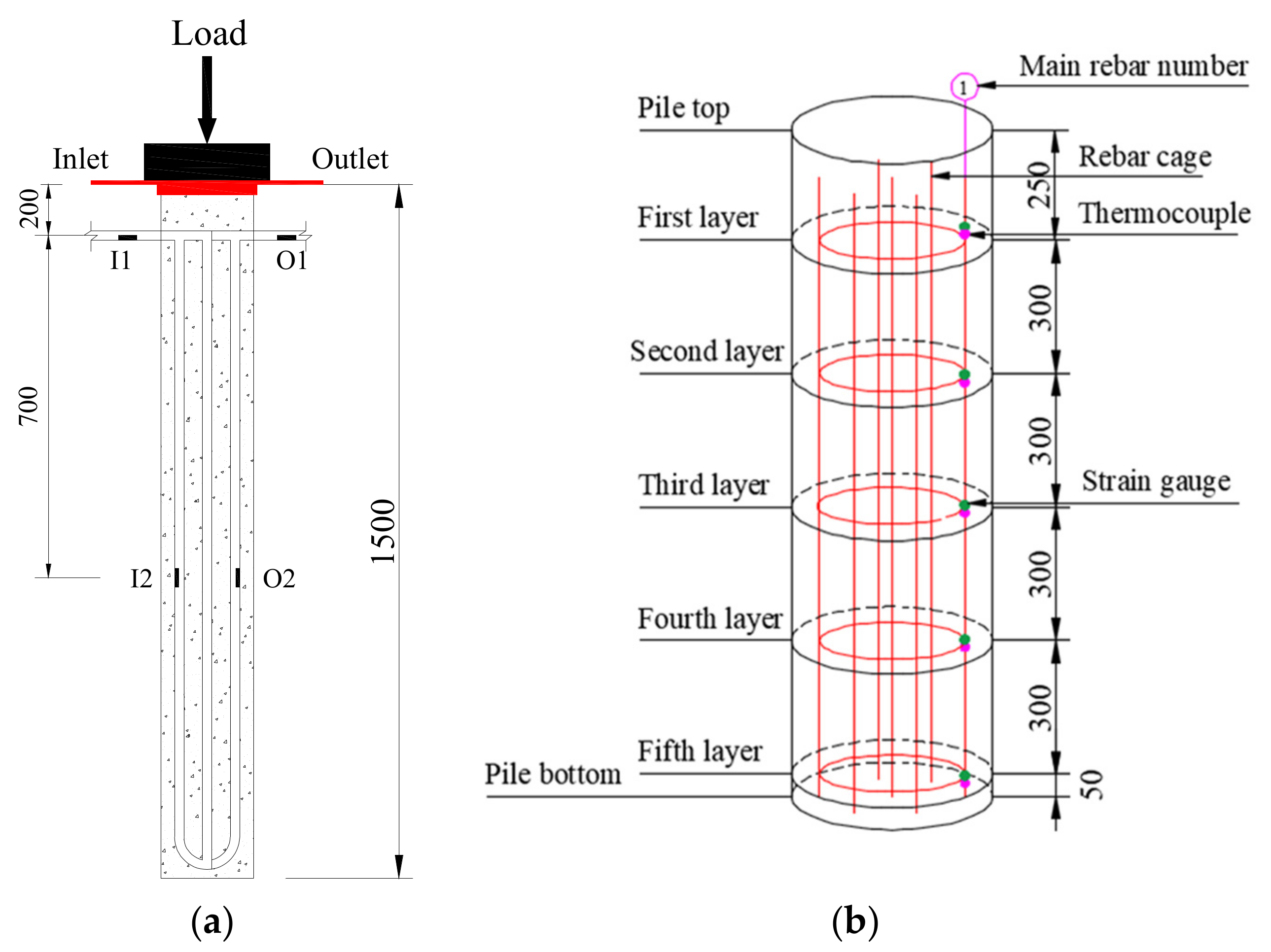
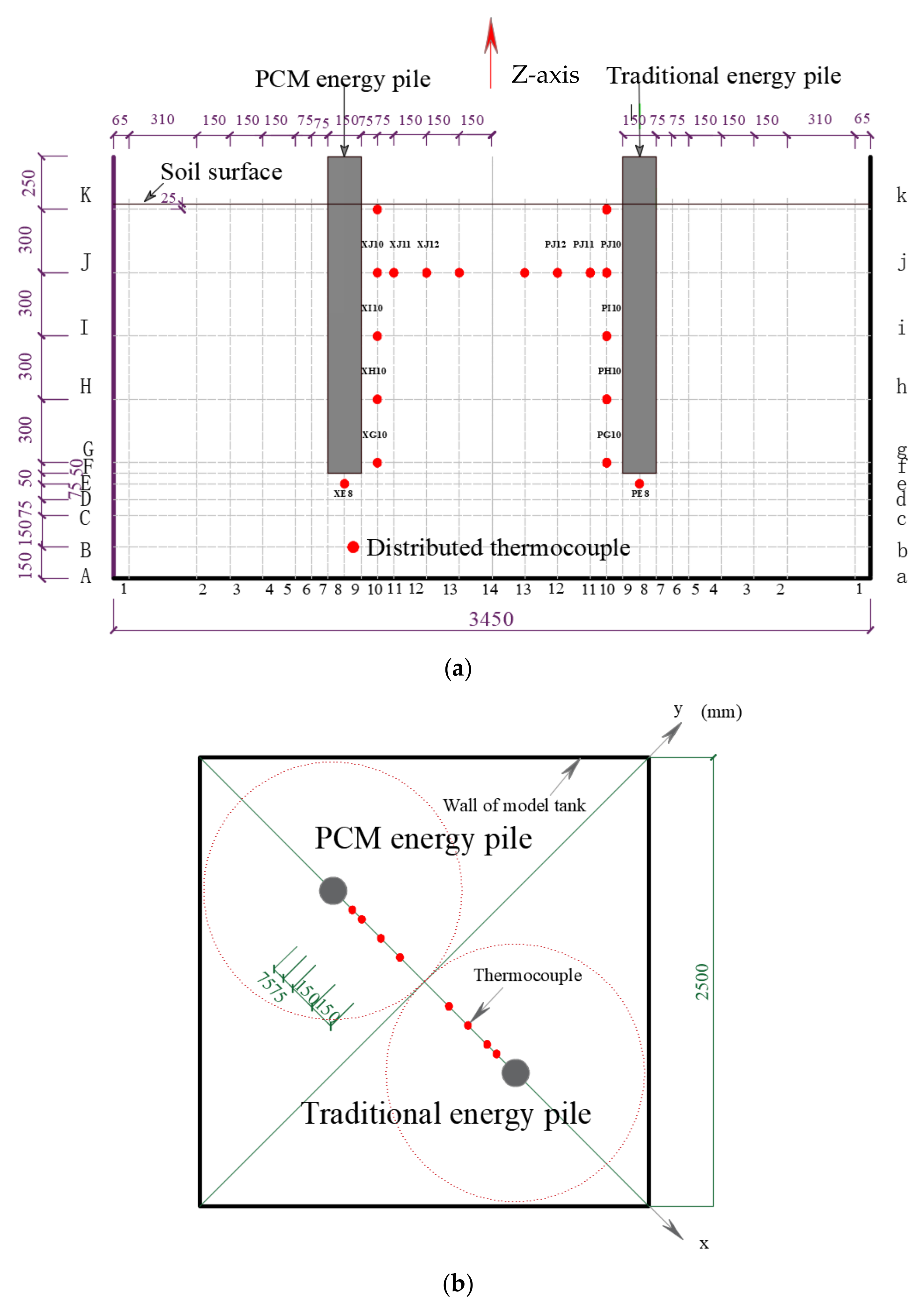
2.1. Tests Preparation

The model piles, whose length is 1.5 m in the present study, are prefabricated type, which are divided into traditional concrete pile and PCM concrete pile to make a comparison. Except for the concrete material of pile body, the remaining specifications of the two piles are the same. For the PCM energy pile, hollow steel balls encapsulated with phase change paraffin were used to replace the coarse aggregate in concrete (Figure 1). Since the surface of hollow steel balls is smoother than natural aggregates, the mechanical bond with the cement matrix would be significantly weakened, and the concrete strength will be reduced accordingly. The tests for compressive strength and elastic modulus were carried out on the ordinary concrete and PCM concrete before casting the model piles. After curing for 28 d, the compressive strengths of ordinary concrete and PCM concrete were 63.78 MPa and 31.92 MPa, respectively, while the values of elastic modulus were 34.8 GPa and 20.1 GPa, respectively. The strength of PCM concrete still meets the requirements for the concrete strength in the pile foundation design.
Adding PCMs into concrete can improve the thermal capacity and energy density of the pile. The parameters of thermo-physical properties of phase change paraffin are listed in Table 1. A designed double U-shaped PE tube was set in the pile body for heating flow as shown in Figure 2. The temperature of water flow was measured by thermocouples arranged at the tube close to the pile. The diameter of the model piles is 0.15 m. Silica sand was selected to make a saturated soil ground and the soil parameters were tested according to the Standard of Geotechnical Test Method [23] as shown in Table 2. According to the study in previous research [24], size effect of soil particles could be negligible in the present model tests because the pile diameter is more than 20 times larger than the size of soil particles.
Before carrying out the pile tests, a saturated sand ground with piles was prepared. First, sand with 5% water content was poured into model tank layer by layer with a total of 18 layers, and the height of each layer was controlled to be 0.1 m by compaction method. After a layer of sand was compacted, chiseling sand surface then poured the next layer of sand to continue compaction. The controlled relative density of sand was 0.55. After the fifth layer of sand was filled which was 0.5 m from the bottom of the tank, the two model piles were placed symmetrically on the diagonal of the tank by using a crane. Then sand filling was continued layer by layer until the specified height of 1.8 m, and 1.3 m of the pile was embedded in soil. During the sand filling process, the uniformity of the sand foundation was verified by taking sand specimens using core cutter at different positions of the soil after each layer was filled. The dry density of the compacted sand was controlled to be around 1.58 g∙cm−3. Finally, the relative density of compaction soil in the tank was 0.55–0.60. After soil filling, water was slowly and evenly added into soil through a water injecting shower on top of the model tank until the water level passed the soil surface.
In the heating-cooling tests on the energy piles, the data of temperature, strain, and displacement of the pile were collected, while temperature, soil pressure, and pore pressure in soil were measured and analyzed. A displacement meter was arranged at the bottom of each pile. The arrangement of thermocouples and strain gauges inside the pile is shown in Figure 3. Sensors for measuring temperature, soil pressure, and pore pressure in soil were buried in the predetermined position during sand filling. The layout of sensors in soil is shown in Figure 4 and Figure 5, respectively.

2.2. Tests Procedure

First, weight plates were loaded step by step on the top of the pile to represent the mass of upper structure. After the weight load was completed and excess pore water pressure fully dissipated, the thermal cycles were applied on the pile through water flow in tubes. The starting temperature of heating-cooling tests was about 26 °C (room temperature) for soil and piles. After heating the pile for 16 h with inlet water of 40 °C at a constant flow rate of 0.12 m3/h, the pile with inlet water of 18.5 °C (minimum indoor comfort temperature) was immediately cooled for 8.5 h at the same flow rate of 0.12 m3/h. A completed heating-cooling cycle consists of one heating stage and one cooling stage. Three thermal cycles for both the traditional pile and PCM pile were performed at the same time, respectively.

3. Results and Discussions

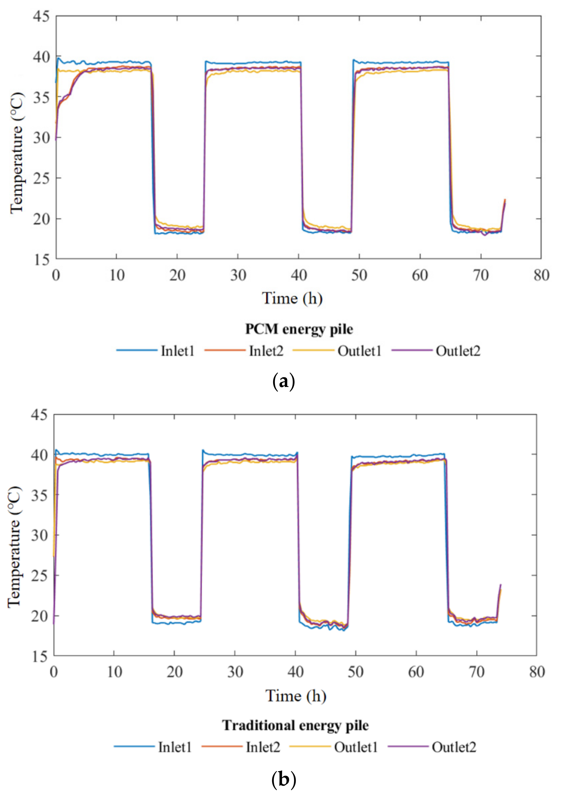
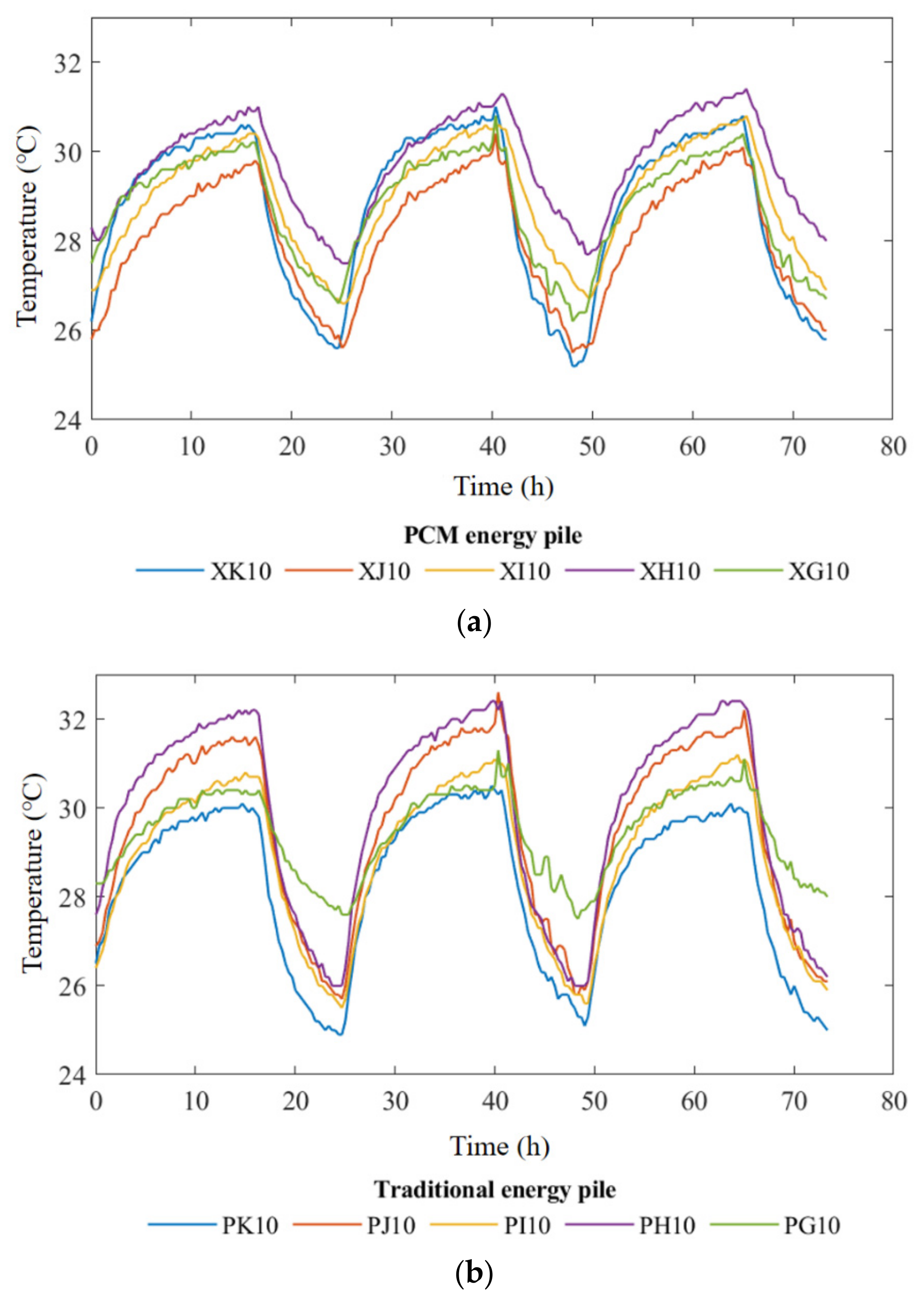
3.1. Influence of Thermal Cycle on Temperatures of Soil and Pile

The temperature change of the circulating water in piles during the repeated heating-cooling cycles is presented in Figure 6. It is clear in Figure 6 that the temperature changed regularly followed with water flow in both the PCM pile and traditional pile. The temperature at the location of inlet points of I1, I2, O1, O2 (Figure 3) in the PCM energy pile were 39.2 °C, 38.6 °C, 38.4 °C, and 38.0 °C, respectively at the end of first heating cycle, while the values of the traditional pile were 39.9 °C, 39.5 °C, 39.5 °C, and 39.2 °C, respectively. Hence, the temperature difference between the inlet and outlet of the PCM pile and was 1.2 °C, while the difference of the traditional pile was only 0.7 °C. Clearly, during the heating process, the temperature difference of the PCM pile was about 70% larger than that of the traditional pile, indicating a relative higher heat transfer efficiency of the PCM pile. On the other hand, a relatively smooth increasing of temperature was observed during the early heating process (0–5 h) in the PCM pile, which indicated that phase change of the encapsulated paraffin occurred, thus the phase change material had functioned well to absorb heat from the circulated water in the heat exchange tube.
Figure 7 shows the change of soil temperature at a depth of 0.325 m at different distance from pile in the horizontal direction. The horizontal distances between points J10-J13 and the pile surface are shown in Figure 4. Clearly, the temperature change value of the PCM pile was smaller than the traditional pile. In the three heating cycles, the peak values at the nearest location of point J10 changed most, that were 29.7 °C, 30 °C, and 30.1 °C, respectively for the PCM pile, while the values for the traditional pile were 31.6 °C, 32.1 °C, and 32.2 °C, respectively. Furthermore, during this repeated heating-cooling process, the temperature for soil in far field position (J13) changed slightly. This slight increase in temperature indicated that during the repeated thermal cycle, the soil had a heat storage effect. Such heat accumulation in the soil might reduce heat exchange and affect the efficiency of energy piles. On the other hand, the temperature change in the soil gradually decreased with the increase of the horizontal distance. As the peak value of temperature at 0.45 m position did not exceed 1 °C, heat transfer could be neglected when the distance exceeded 0.45 m which is three times the pile diameter. This result means that when using energy piles in groups, the spacing between piles should be fully considered to avoid the influence of heat exchange between the piles and soil.
The soil temperature change at different depths 0.075 m away from the pile is shown in Figure 8. The soil depth of position K, J, I, H, and G are 0.025 m, 0.325 m, 0.625 mm, 0.925 m, and 1.225 m from soil surface, respectively. The change trend of soil temperature at different depths was the same. The temperature of the soil varies greatly from 0 to 8 h during heating stages, and the temperature change of both types of energy pile after 8 h was very slow. Furthermore, the soil temperature kept increasing during the 16 h heating period, which indicated that the heat storage of the soil did not reached its capacity in the test. The highest soil temperature appeared at the depth of 0.925 m for the two piles. Compared with the traditional pile, the temperature fluctuation in soil near the PCM pile was lower, indicating that the phase change material could play a notable role in temperature control.
Figure 9 shows the temperature changes of No. 1 steel bars observed at different depths during three thermal cycles. In Figure 9, the temperature at the bottom (No. 5 position) of both piles was the lowest compared with the other positions in heating stage. The reason for this phenomenon is that the flow temperature in the heat exchange tubes decreased due to thermal transmission. The temperature fluctuation for the soil beneath the energy pile was moderate which provided a passage of heat emission. Meanwhile, the temperature change trends at positions 3 and 4 were similar. During the heating process, the observed temperature value decreased with increasing depth, but the temperature change was nonlinear. Within 5 h of the first heating cycle, a temperature transition zone appeared in the temperature of the PCM energy pile, while such a plateau stage was not observed from the temperature change curve of the traditional energy pile. The phenomenon could be explained by the fact that the temperature of the phase change material had reached its phase change temperature, and a phase change process had occurred.

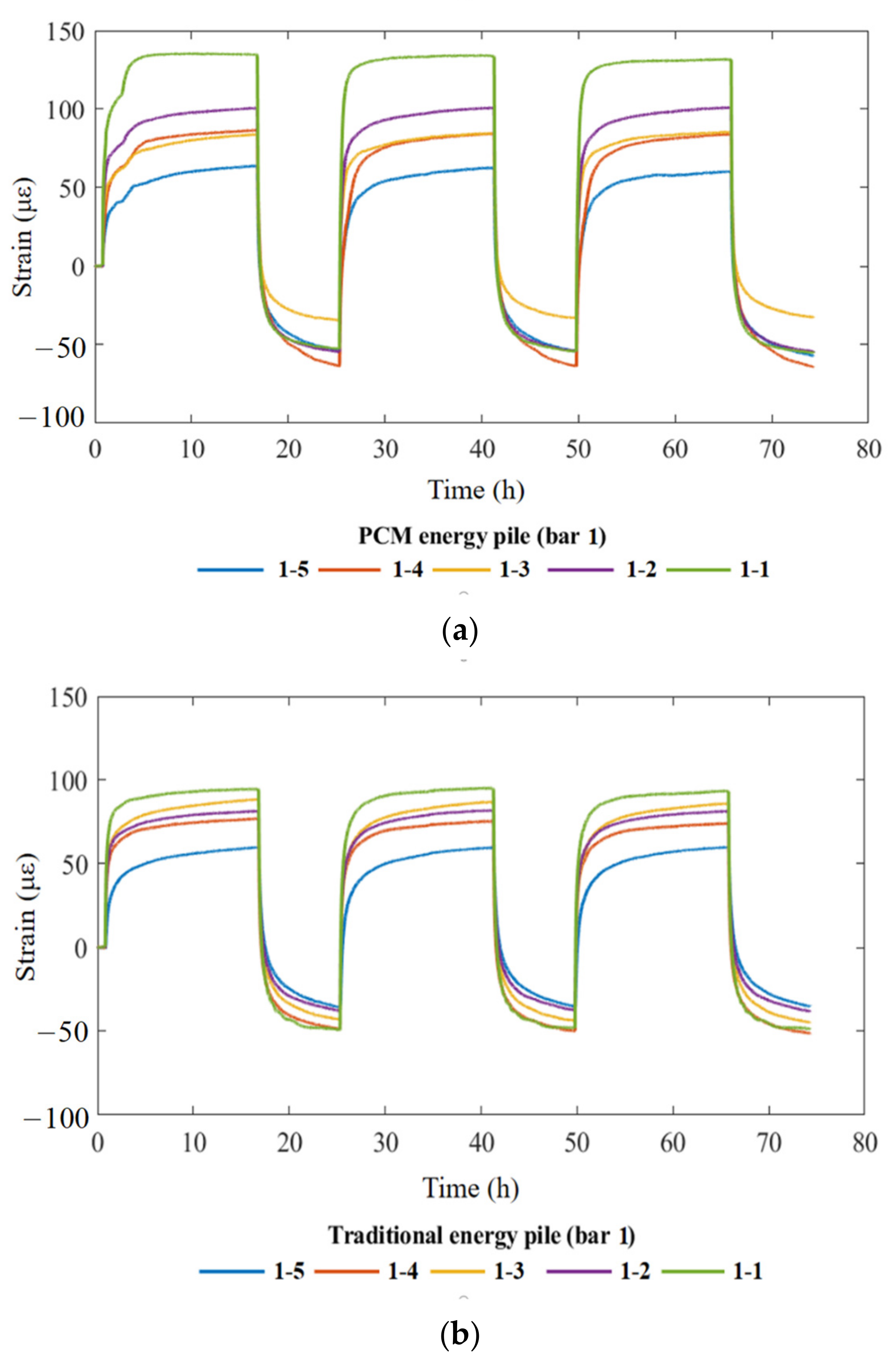
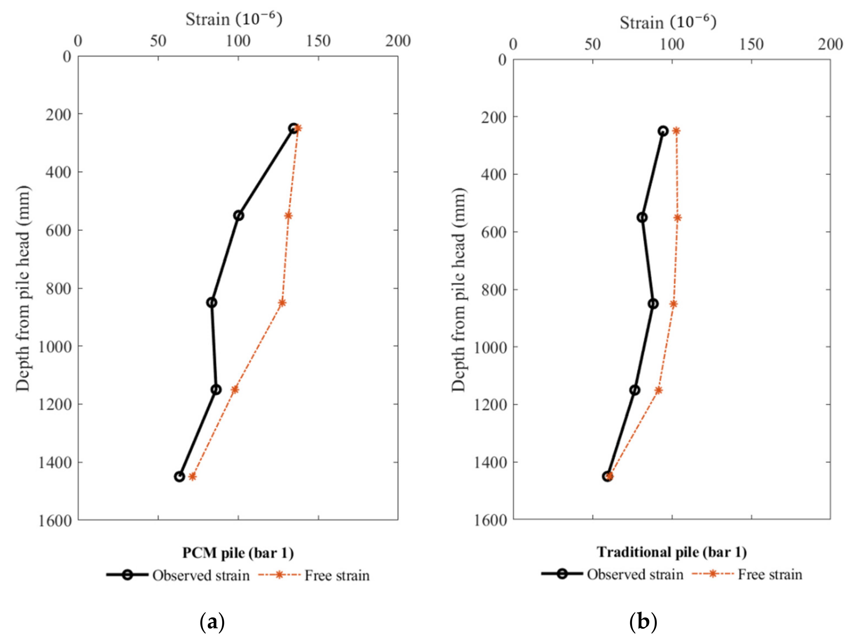
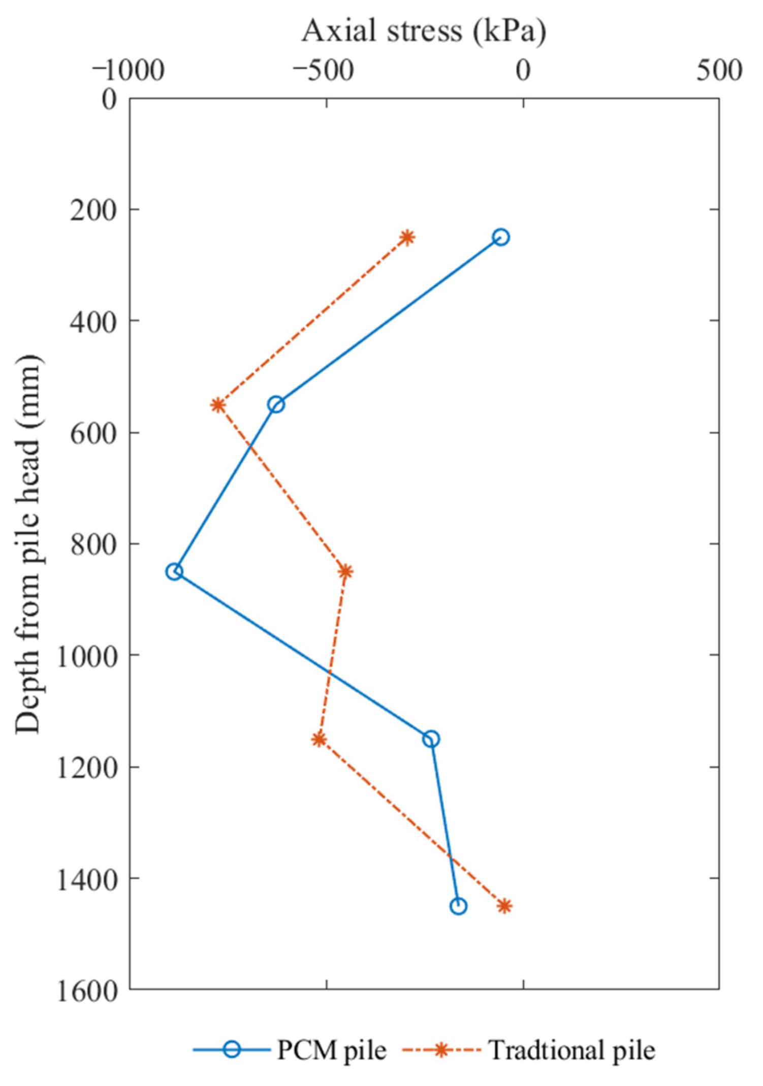
3.2. Influence of Thermal Cycle on Strains and Stress in the Pile

The thermal strain inside the pile was analyzed. Since the steel and concrete have similar coefficients of thermal expansion and there is not much difference in strain change when used together [11], the strain of steel was used to represent the strain of the pile. If the pile is completely unconstrained, the free strain generated by temperature change should be:
ε free = α c Δ T
In Equation (1), ε free is the free thermal strain, α c is the material coefficient of thermal expansion, and Δ T is the value of temperature change.
However, in the actual situation, the pile was restrained by the soil and upper loads that could not expand freely. The restraint thermal strain is
ε Rstr = ε Free ε Obs
that ε Rstr is the restraint thermal strain of pile, and ε Obs is the observed thermal strain.
Figure 10 shows the time history of thermal strain of No. 1 steel bar observed at different depths during three thermal cycles. In Figure 10, as the measured point of No. 1–1 in the two piles was located at shallow depth near the water inlet, resulting in higher thermal strain compared with the other points of 1–2, 1–3, 1–4 and 1–5. The change trend of thermal strain was similar at different depths, presenting a decreasing trend with the depth for both the PCM pile and traditional pile. However, at the same depth, thermal strain in the PCM pile was larger than that in the traditional pile. This difference was attributed to the pile materials that PCM could absorb more heat and caused larger thermal strain. The value of observed thermal strain decreased with increasing depth, but the change in strain value was nonlinear. In addition, a certain amount of shrinkage strain (negative value) was observed during cooling stage because the temperature decreased below the room condition (about 26 °C).
Figure 11 shows the values of observed strain and free strain of steel bars along depth after first heating stage. The observed strain at both ends of two piles was close to the values generated by the free expansion near the pile end, indicating that the end restraint effect was small, and the pile could freely expand. Compared with the traditional pile, the strain difference between the observed and free thermal strain on steel bars of the PCM pile was larger, which was mainly because of the difference for their expansion coefficient. As the PCM concrete used hollow steel balls encapsulating with paraffin to replace the coarse aggregates in the traditional concrete, the thermal expansion coefficient of the pile body could be increased, which brought greater thermal deformation to the pile body, and more constraint on the pile body by surrounding soil. The feature of thermal strain change in the present test was similar with on-site experimental results [3,4]. Since the static load applied at pile head was small and the pile body can expand quite easily, the difference between the observed strains and free thermal strains of the two piles was small.
Furthermore, the axial stress was calculated by a formula as following [25].
σ T = E ε Rstr = E ε Obs ε Free
where E is elastic modulus, ε Rstr is the restraint thermal strain, ε Obs is the observed thermal strain, and ε Free is the free thermal strain.
Figure 12 shows the change in the stress of the steel bars after the first heating stage in the two energy piles. The two piles present the similar distribution tendency that the compressive stress at the middle part (negative values) was larger than the two ends. Except for the depth around −0.85 m below soil surface, the stress of the PCM pile was smaller than the traditional pile in general. The reason for the relatively large value of the PCM pile and small value of the traditional pile at depth of −0.85 m should be confirmed in future study. On the other hand, the additional axial stress caused by temperature change in the use of energy piles cannot be neglected because the long-term thermal loading might bring concrete fatigue. This result confirmed the simulation results of thermo-mechanical performance of pile geothermal heat exchanger (PGHE) considering temperature-dependent interface behavior [26].
The lateral friction of piles can be calculated by the difference of thermal stress [27,28]. The specific calculation is shown in the following Equation (4).
f s , m o b , j = ( σ T , j σ T , j 1 ) D 4 Δ l
where f s , m o b , j is side friction resistance of pile, D is pile diameter, Δ l is distance between two adjacent measuring points, and σ T , j σ T , j 1 is the stress difference between two adjacent measuring points [11].
The upward of lateral friction is assumed to be positive and the downward is negative. As mentioned in the previous section, the stress difference occurred on the same section, then the lateral friction at corresponding points on the pile side surface was calculated by the above-mentioned Formula (4), and the results are drawn in Figure 13. In the figure, the direction of the lateral friction also reflected the constraint of pile when loaded by heating. The positive and negative changes of the friction force near the middle of the pile, and this result was in agreement with the concept of neutral plane in the existing studies [4,12].

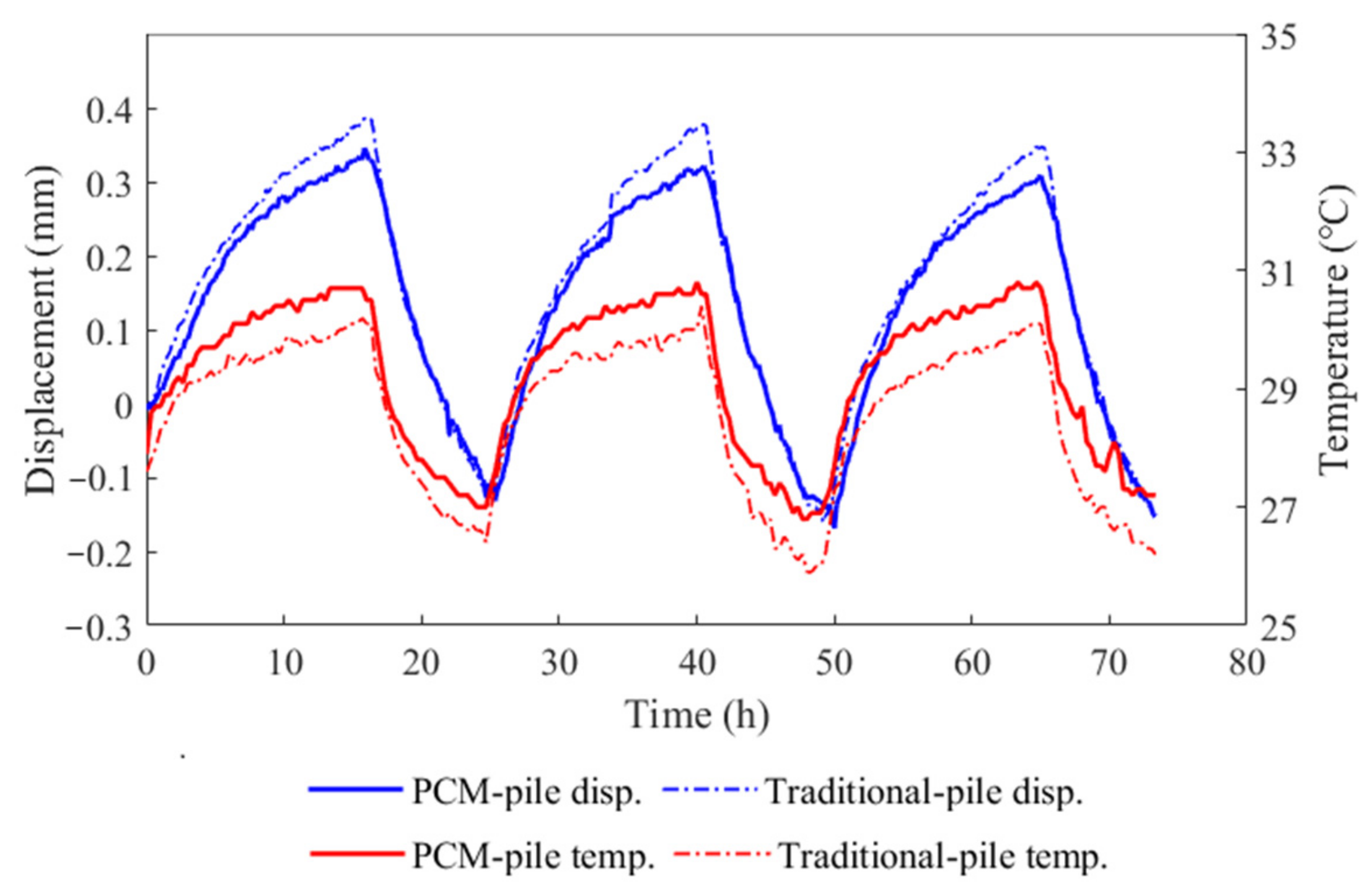
3.3. Displacement of Pile

The time history of displacement and corresponding temperature change on pile bottom is shown in Figure 14. It is assumed that the downward displacement is positive and the upward is negative. The temperature changes of soil 50 mm under the pile bottoms of two types of energy piles are also presented in Figure 14. It is quite obvious that the fluctuation of temperature and displacement for traditional energy pile were larger than that of the PCM energy pile, which confirmed that the PCM helped to reduce the uneven thermal response of soil-pile interaction. At the beginning of heating, the pile expanded rapidly due to the large rate of temperature change, and the pile bottom displacements demonstrated a downward trend. In contrast, during the cooling duration, the downward displacements recovered quickly, and even showed some upward displacements. From the displacement results at the end of cooling mode for each cycle, a certain degree of displacement accumulation was observed, indicating that unrecoverable plastic deformation occurred during the repeated heating-cooling cycles. The produced cumulative strain of the pile with the increase of cycle number was also reported in the study through the simulation results of the energy pile under the cyclic heating load for 30 years [29]. From this cumulative strain, it was inferred that the soil constraint stress to pile was reduced and corresponding pile expansion increased, resulting in more pile displacement. Meanwhile, the soil around the pile would expand during the heating process. This expansion would cause the soil particles to squeeze each other, which would cause the compaction effect of the soil particles during the repeated heating-cooling processes. According to the results shown in Figure 14, when increasing the number of heating cycles, the displacement at the bottom of the two energy piles showed a slight decrease during heating stage, which means that the soil beneath the energy pile may be condensed due to the pile expansion in heating stage. In other words, soil compressibility and strength can be affected by repeated temperature change and therefore can affect the capacity of pile, resulting in cumulative settlement at the pile bottom. This point was also emphasized in the study on the long-term performance of heat exchanger piles [29]. It was emphasized that cumulative displacement of pile and repeated thermal loading would affect the durability of energy pile and upper buildings, to which attention should be paid in the design.

3.4. Soil Pressure and Pore Pressure

Figure 15 and Figure 16 show the changes of soil pressure and pore pressure beneath the energy piles. In Figure 15, the soil pressure increased rapidly to the maximum value at the beginning of each heating stage, and then decreased slowly in a roughly linear manner. As explained in a previous section, the temperature fluctuation of soil induced by the PCM pile was smaller, an interesting phenomenon was observed that the soil pressure decreasing rate of PCM energy pile was more significant than the rate of traditional energy pile. With the increase of thermal cycle, the difference of soil pressure between the two piles also increased. Since the energy pile mainly transferred heat in the radial direction, rapid thermal expansion of soil particles at the bottom of the pile did not occur. Therefore, the reason for the sudden rise of the soil pressure at the bottom of the pile came from the expansion and compression of the pile, which could be verified from the change of pile strain in Figure 10. Meanwhile, the pore pressure generated by temperature change surrounded the two piles was quite small in Figure 16. Furthermore, it could be observed that the appearance and dissipation speed of pore pressure in soil beneath the PCM energy pile was much quicker than that beneath the traditional pile.

4. Conclusions

A large-scale model test was conducted on a new type of energy pile produced by using hollow steel balls encapsulating phase-change paraffin to replace the aggregate of the concrete. Repeated heating-cooling cycles were applied on the energy pile buried in saturated sand at a constant inlet water temperature. The thermal response of pile and surrounding soil were observed and analyzed in comparison with the traditional concrete pile. The following conclusions can be drawn.
(1)
During the heating process, the temperature difference of the PCM pile was about 70% larger than that of the traditional pile, indicating a relative higher heat transfer efficiency of the PCM pile. A relatively smooth increasing of temperature at initial heating stage indicated that phase change material had functioned well to absorb heat from the circulated water to slow down the temperature fluctuation in the pile.
(2)
Due to the repeated heating-cooling cycles on the PCM energy pile, the soil temperature change surrounding the PCM energy pile during the heating stage showed a relatively small range within three times the pile diameter.
(3)
Thermal strain in the PCM pile was larger than that in the traditional pile attributed to more heat absorption of PCM. Meanwhile, the axial stress caused by thermal loading along the depth of the PCM pile was smaller than the traditional pile in general.
(4)
The generated soil pressure and excess pore pressure during thermal loading for the soil beneath the PCM energy pile was a little smaller than that for the traditional energy pile since the temperature fluctuation for soil surrounded the PCM energy pile is relatively moderate.
(5)
Cumulative displacement of pile in heating-cooling cycles was observed. This cumulative displacement would lead to a larger pile settlement and affect the safety of the upper buildings. Attention should be paid to this in the design.

Author Contributions

Conceptualization, X.B. and H.C.; methodology, X.Q., J.Z. and X.B.; validation, X.X. and X.B.; formal analysis, X.B.; investigation, X.B. and H.C.; resources, X.B. and H.C.; data curation, X.B. and H.C.; writing—original draft preparation, X.B., X.Q., J.Z. and X.X.; writing—review and editing, X.B. and H.C.; visualization, X.Q. and J.Z.; supervision, X.B. and H.C.; project administration, H.C.; funding acquisition, H.C. All authors have read and agreed to the published version of the manuscript.

Funding

This research was funded by the National Natural Science Foundation of China, grant number 51925804&51938008 and Technical Innovation Foundation of Shenzhen, grant number JCYJ20190808112203700.

Institutional Review Board Statement

Not applicable.

Informed Consent Statement

Written informed consent has been obtained from the patient(s) to publish this paper.

Data Availability Statement

The data presented in this study are available on request from the corresponding author.

Acknowledgments

This research was fully supported by the national Natural Science Foundation of China (No. 51925804&51938008), and Technical Innovation Foundation of Shenzhen (Grant No. JCYJ20190808112203700).

Conflicts of Interest

The authors declare no conflict of interest.

References

  1. Delmastro, C.; Lavagno, E.; Schranz, L. Energy and underground. Tunn. Undergr. Space Technol. 2016, 55, 96–102. [Google Scholar] [CrossRef]
  2. Yu, L.; Zhang, D.; Fang, Q.; Cao, L.; Xu, T.; Li, Q. Surface settlement of subway station construction using pile-beam-arch approach. Tunn. Undergr. Space Technol. 2019, 90, 340–356. [Google Scholar] [CrossRef]
  3. Laloui, L.; Nuth, M.; Vulliet, L. Experimental and numerical investigations of the behaviour of a heat exchanger pile. Int. J. Numer. Anal. Methods Geomech. 2006, 30, 763–781. [Google Scholar] [CrossRef]
  4. Bourne-Webb, P.; Amatya, B.; Soga, K.; Amis, T.; Davidson, C.; Payne, P. Energy pile test at Lambeth College, London: Geotechnical and thermodynamic aspects of pile response to heat cycles. Géotechnique 2009, 59, 237–248. [Google Scholar] [CrossRef]
  5. Amatya, B.; Soga, K.; Bourne-Webb, P.; Amis, T.; Laloui, L. Thermo-mechanical behaviour of energy piles. Géotechnique 2012, 62, 503–519. [Google Scholar] [CrossRef]
  6. Akrouch, G.A.; Sa’nchez, M.; Briaud, J.L. Thermo-mechanical behavior of energy piles in high plasticity clays. Acta Geotech. 2014, 9, 399–412. [Google Scholar] [CrossRef]
  7. Loveridge, F.; Holmes, G.; Roberts, T.; Powrie, W. Thermal response testing through the Chalk aquifer in London, UK. Proc. Inst. Civ. Eng. Geotech. Eng. 2013, 166, 197–210. [Google Scholar] [CrossRef] [Green Version]
  8. Gao, J.; Zhang, X.; Liu, J.; Li, K.; Yang, J. Numerical and experimental assessment of thermal performance of vertical energy piles: An application. Appl. Energy 2008, 85, 901–910. [Google Scholar] [CrossRef]
  9. Hamada, Y.; Saitoh, H.; Nakamura, M.; Kubota, H.; Ochifuji, K. Field performance of an energy pile system for space heating. Energy Build. 2006, 39, 517–524. [Google Scholar] [CrossRef]
  10. Ren, L.-W.; Xu, J.; Kong, G.-Q.; Liu, H.-L. Field tests on thermal response characteristics of micro-steel-pipe pile under multiple temperature cycles. Renew. Energy 2019, 147, 1098–1106. [Google Scholar] [CrossRef]
  11. Stewart, M.A.; Mccartney, J.S. Centrifuge Modeling of Soil-Structure Interaction in Energy Foundations. J. Geotech. Geoenviron. Eng. 2014, 140, 4013044. [Google Scholar] [CrossRef]
  12. Ng, C.; Shi, C.; Gunawan, A.; Laloui, L.; Liu, H. Centrifuge modelling of heating effects on energy pile performance in saturated sand. Can. Geotech. J. 2015, 52, 1045–1057. [Google Scholar] [CrossRef]
  13. Ng, C.; Farivar, A.; Gomaa, S.; Shakeel, M.; Jafarzadeh, F. Performance of elevated energy pile groups with different pile spacing in clay subjected to cyclic non-symmetrical thermal loading. Renew. Energy 2021, 172, 998–1012. [Google Scholar] [CrossRef]
  14. Kramer, C.A.; Ghasemi-Fare, O.; Basu, P. Laboratory Thermal Performance Tests on a Model Heat Exchanger Pile in Sand. Geotech. Geol. Eng. 2014, 33, 253–271. [Google Scholar] [CrossRef]
  15. Kalantidou, A.; Tang, A.M.; Pereira, J.-M.; Hassen, G. Preliminary study on the mechanical behaviour of heat exchanger pile in physical model. Géotechnique 2012, 62, 1047–1051. [Google Scholar] [CrossRef] [Green Version]
  16. Yavari, N.; Tang, A.M.; Pereira, J.-M.; Hassen, G. Experimental study on the mechanical behaviour of a heat exchanger pile using physical modelling. Acta Geotech. 2014, 9, 385–398. [Google Scholar] [CrossRef]
  17. Goode, J.C.; McCartney, J.S. Centrifuge Modeling of End-Restraint Effects in Energy Foundations. J. Geotech. Geoenviron. Eng. 2015, 141, 04015034. [Google Scholar] [CrossRef] [Green Version]
  18. Bao, X.; Li, Y.; Feng, T.; Cui, H.; Chen, X. Investigation on thermo-mechanical behavior of reinforced concrete energy pile with large cross-section in saturated sandy soil by model experiments. Undergr. Space 2019, 5, 229–241. [Google Scholar] [CrossRef]
  19. Caulk, R.; Ghazanfari, E.; McCartney, J.S. Parameterization of a calibrated geothermal energy pile model. Géoméch. Energy Environ. 2016, 5, 1–15. [Google Scholar] [CrossRef] [Green Version]
  20. Bottarelli, M.; Bortoloni, M.; Su, Y.; Yousif, C.; Aydın, A.A.; Georgiev, A. Numerical analysis of a novel ground heat exchanger coupled with phase change materials. Appl. Therm. Eng. 2015, 88, 369–375. [Google Scholar] [CrossRef]
  21. Qi, D.; Pu, L.; Sun, F.; Li, Y. Numerical investigation on thermal performance of ground heat exchangers using phase change materials as grout for ground source heat pump system. Appl. Therm. Eng. 2016, 106, 1023–1032. [Google Scholar] [CrossRef]
  22. Han, C.; Yu, X. An innovative energy pile technology to expand the viability of geothermal bridge deck snow melting for different United States regions: Computational assisted feasibility analyses. Renew. Energy 2018, 123, 417–427. [Google Scholar] [CrossRef]
  23. Standard for Soil Test Method: GB/T50123—1999. State Bureau of Quality and Technical Supervision. 1999. Available online: http://www.lancarver.com/En/bz_view.asp?id=229 (accessed on 1 October 2021). (In English).
  24. Parkin, A.K.; Lunne, T. Boundary effects in the laboratory calibration of a cone penetrometer in sand. Nor. Geotech. Inst. Publ. 1982, 2, 761–768. [Google Scholar]
  25. Gashti, E.H.N.; Malaska, M.; Kujala, K. Evaluation of thermo-mechanical behaviour of composite energy piles during heating/cooling operations. Eng. Struct. 2014, 75, 363–373. [Google Scholar] [CrossRef]
  26. Wang, D.; Lu, L.; Cui, P. Simulation of thermo-mechanical performance of pile geothermal heat exchanger (PGHE) considering temperature-depend interface behavior. Appl. Therm. Eng. 2018, 139, 356–366. [Google Scholar] [CrossRef]
  27. Murphy, K.D.; McCartney, J.S.; Henry, K.S. Evaluation of thermo-mechanical and thermal behavior of full-scale energy foundations. Acta Geotech. 2014, 10, 179–195. [Google Scholar] [CrossRef]
  28. Song, H.; Pei, H.; Xu, D.; Cui, C. Performance study of energy piles in different climatic conditions by using multi-sensor technologies. Measurement 2020, 162, 107875. [Google Scholar] [CrossRef]
  29. Olgun, C.G.; Ozudogru, T.Y.; Abdelaziz, S.L.; Senol, A. Long-term performance of heat exchanger piles. Acta Geotech. 2014, 10, 553–569. [Google Scholar] [CrossRef]
Figure 1. Precast PCM energy pile for model tests. (a) Casted PCM energy pile. (b) Test of concrete.
Symmetry 13 01958 g001
Figure 2. The structure of steel and heat exchange tube inside PCM energy pile. (a) Steel bars and heat exchange tubes. (b) Circulating route in tubes.
Symmetry 13 01958 g002
Figure 3. Measurement inside the pile (unit: mm). (a) Thermocouples on tube. (b) Strain gauges and thermocouples on the steel.
Symmetry 13 01958 g003
Figure 4. Position of soil pressure and pore pressure sensors symmetrically arranged in soil (unit: mm).
Symmetry 13 01958 g004
Figure 5. Distribution of thermocouples for temperature measurement symmetrically arranged in soil. (a) Side view (unit: mm). (b) Plane view (unit: mm).
Symmetry 13 01958 g005
Figure 6. The time history of internal temperature of heat exchange tube in the piles. (a) PCM energy pile. (b) Traditional energy pile.
Symmetry 13 01958 g006
Figure 7. The time history of soil temperature in horizontal direction 0.325 m below soil surface. (a) PCM energy pile. (b) Traditional energy pile.
Symmetry 13 01958 g007
Figure 8. The time history of soil temperature at different depth. (a) PCM energy pile. (b) Traditional energy pile.
Symmetry 13 01958 g008
Figure 9. The time history of observed temperature change of No. 1 steel bar. (a) PCM energy pile. (b) Traditional energy pile.
Symmetry 13 01958 g009
Figure 10. The time history of observed thermal strain of No. 1 steel bar. (a) PCM energy pile. (b) Traditional energy pile.
Symmetry 13 01958 g010
Figure 11. Strain change of different bars along depth after first heating stage (a,b).
Symmetry 13 01958 g011
Figure 12. Distribution of pile axial stress with depth.
Symmetry 13 01958 g012
Figure 13. Distribution of pile side frictional resistance along the depth after the first heating stage.
Symmetry 13 01958 g013
Figure 14. The time history of soil settlement and temperature below pile bottom.
Symmetry 13 01958 g014
Figure 15. Change of soil pressure beneath the energy piles.
Symmetry 13 01958 g015
Figure 16. Change of pore pressure beneath the energy piles.
Symmetry 13 01958 g016
Table 1. Parameters of thermophysical properties of paraffin.
ParameterSolidLiquid
Density (kg/m3)833.8786.7
Heat conductivity (W/(m K)0.30.167
Specific heat capacity (J/g °C)2.162.02
Phase change temperature (°C)23 ± 1 °C
Latent heat (J/g)188.04
Table 2. Parameters of used sand.
ParameterValueParameterValue
Cu3.78 φ c 27.1°
Cc1.06 e m a x 0.86
ρ d m i n / g · cm 3 1.44 e m i n 0.58
ρ d m a x / g · cm 3 1.70D50/mm0.28
ρ s / g · cm 3 2.68
Publisher’s Note: MDPI stays neutral with regard to jurisdictional claims in published maps and institutional affiliations.

