4.1. Algorithm Analysis Steps
When the subway vehicle passes through the horizontal curve, a certain angle will be generated between the front and rear vehicles, and the size of the angle is greatly related to the safety of the vehicle through the horizontal curve [
27,
28]. Using geometric analysis and geometric graphing method, the geometric position and hook swing angle of the vehicle when passing the curve can be calculated.
After completing the design of the line and vehicle characteristics parameters, and selecting the appropriate hook type, the curve linkage performance of the vehicle can be determined. It also determines the maximum number of hook swing angle that the vehicle can achieve when passing the curve, and takes the hook state at this moment as the limit working condition under the corresponding line conditions. At this time, the hook slowing device will unhook, so that the two vehicles are free to approach, to simulate the working scenario of the curve rescue linkage. By calculating and analyzing the trajectory motion characteristics of trains on fixed circular curves, straight line into curves and S-curves to verify whether the hooks can be automatically linked, thus obtaining the actual linkage of hooks on horizontal curves.
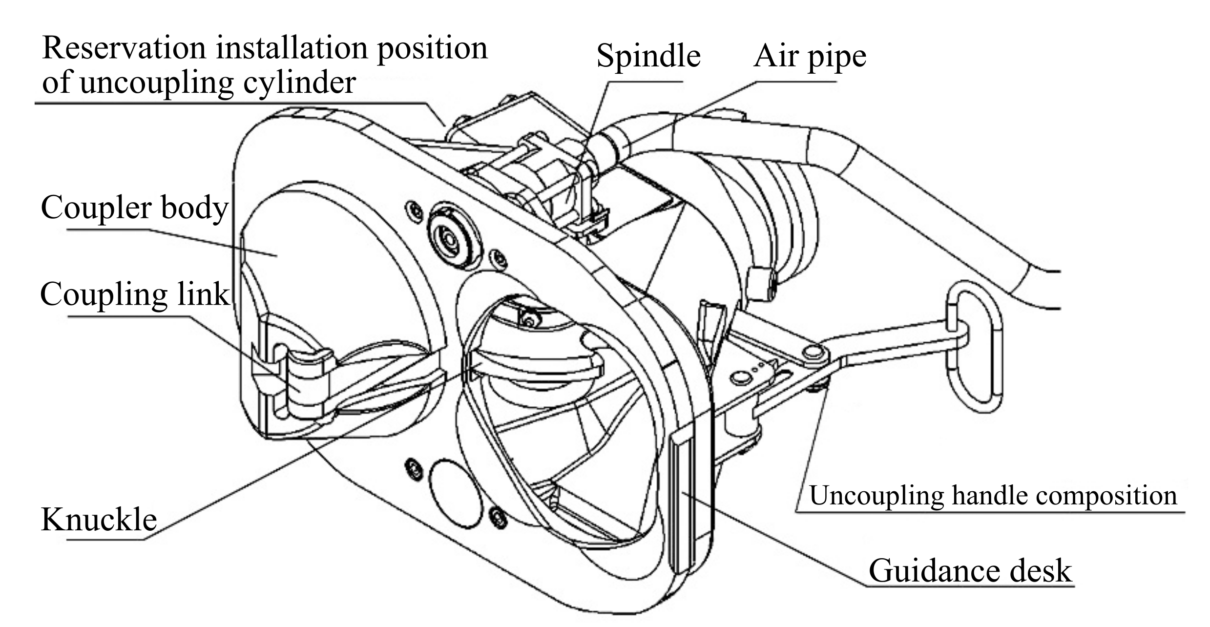
The mechanical structure of the coupler head allows a certain horizontal and vertical position difference when the vehicle is automatically connected, i.e., the two hook heads that are being connected theoretically allow automatic connection under working conditions with a relative position difference. After the on-site vehicle connection test, to ensure that the coupler can be safely connected on the curve, it must be ensured that the projection of the apex of the coupler convex cone on the coupler connecting surface is within the connectable area.
Figure 8 shows the hooking range of the vehicle [
29].
Secondly, determine whether the hook body and the line connecting the center of rotation of the hook can form a triangle,
Figure 9 shows the schematic diagram of the coupler successful connection,
Figure 10 shows the schematic diagram of the coupler failure connection [
30].
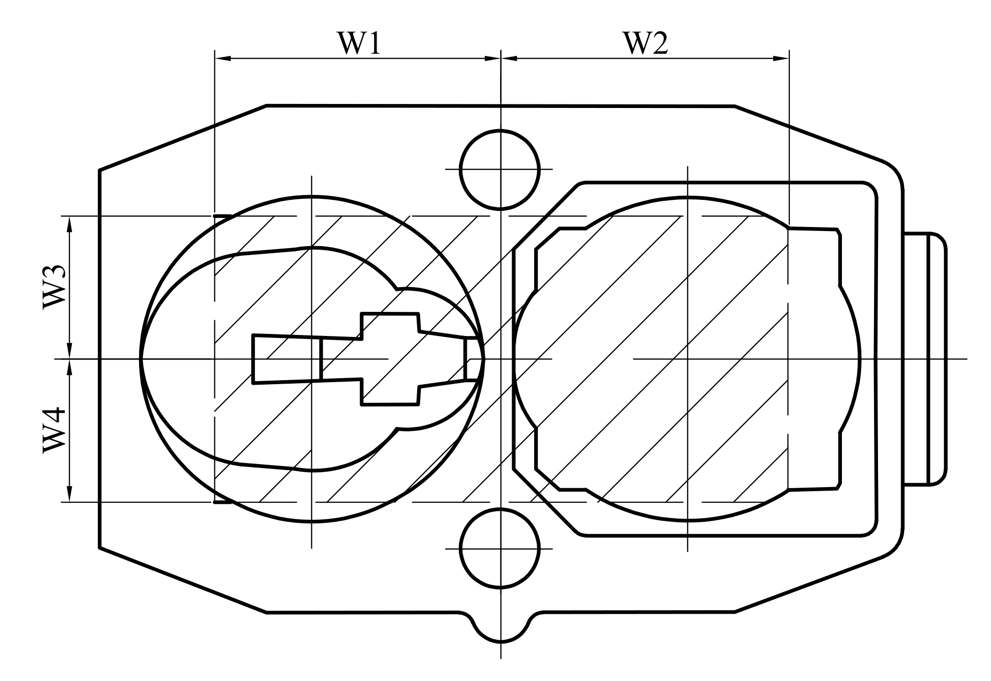
To simplify the calculation, we use
Figure 11 to geometrically simplify the top view of the two vehicle hooks during their connection. In the schematic diagram, the two semi-elliptic curves at point
and point
are the simplified graphs of the hook convex cones, and both points are located at the centers of the semi-elliptic curves, which are the vertices of the hook convex cones. The lengths of
and
from
are
and
, respectively; the lengths of
and
from
are
and
, respectively. Where the geometric meanings of
and
are the same as those of
and
in
Figure 8.
Finally, as shown in
Figure 11, it is necessary to ensure that the orthographic projections of
and
can fall within line segment
and line segment
, respectively, if the hook can be safely attached on the curve. In other words, it should be ensured that the six angles in the characteristic triangles
and
of the coupler in
Figure 10 are all acute angles.
In summary, we propose a calculation method to determine whether the hook can realize the curve rescue linkage, and Algorithm step flow is shown in
Figure 12.
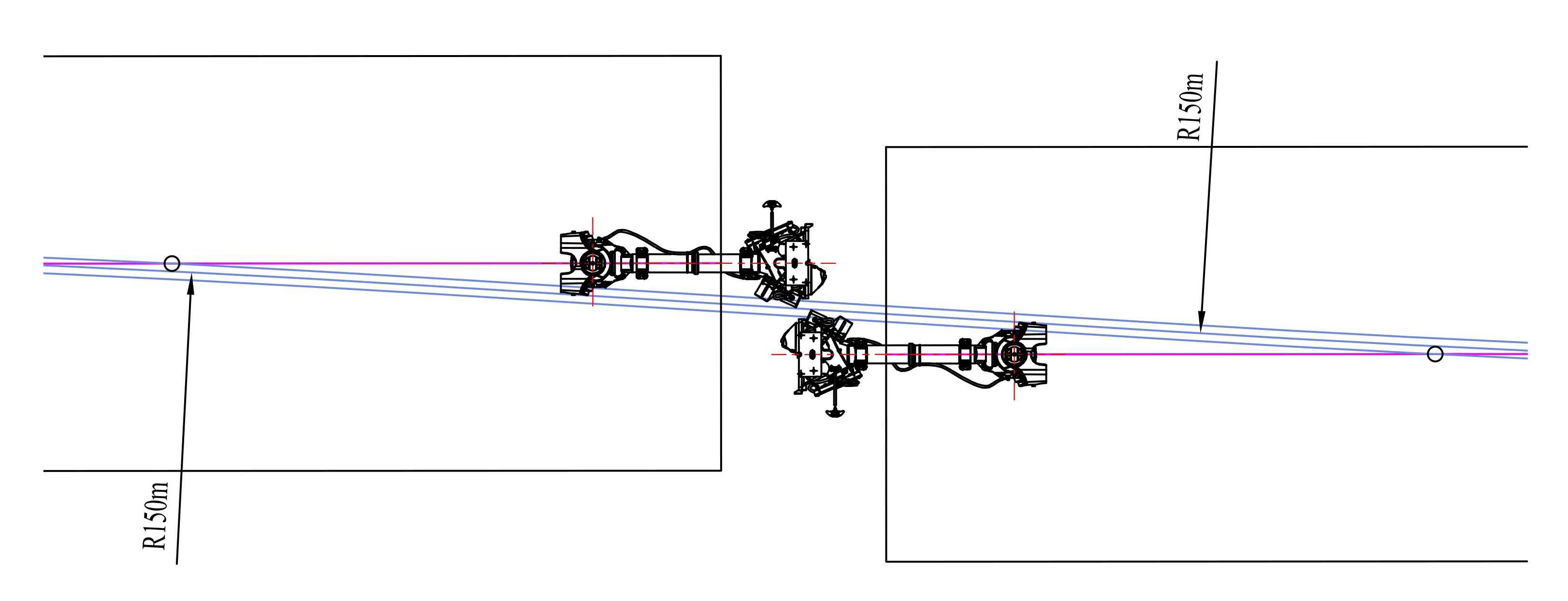
4.2. Determination Method of the Coupler Swing Angle under Horizontal Curve
Take the example of circular curve working condition, the calculation method of the coupler’s swing angle [
31,
32],
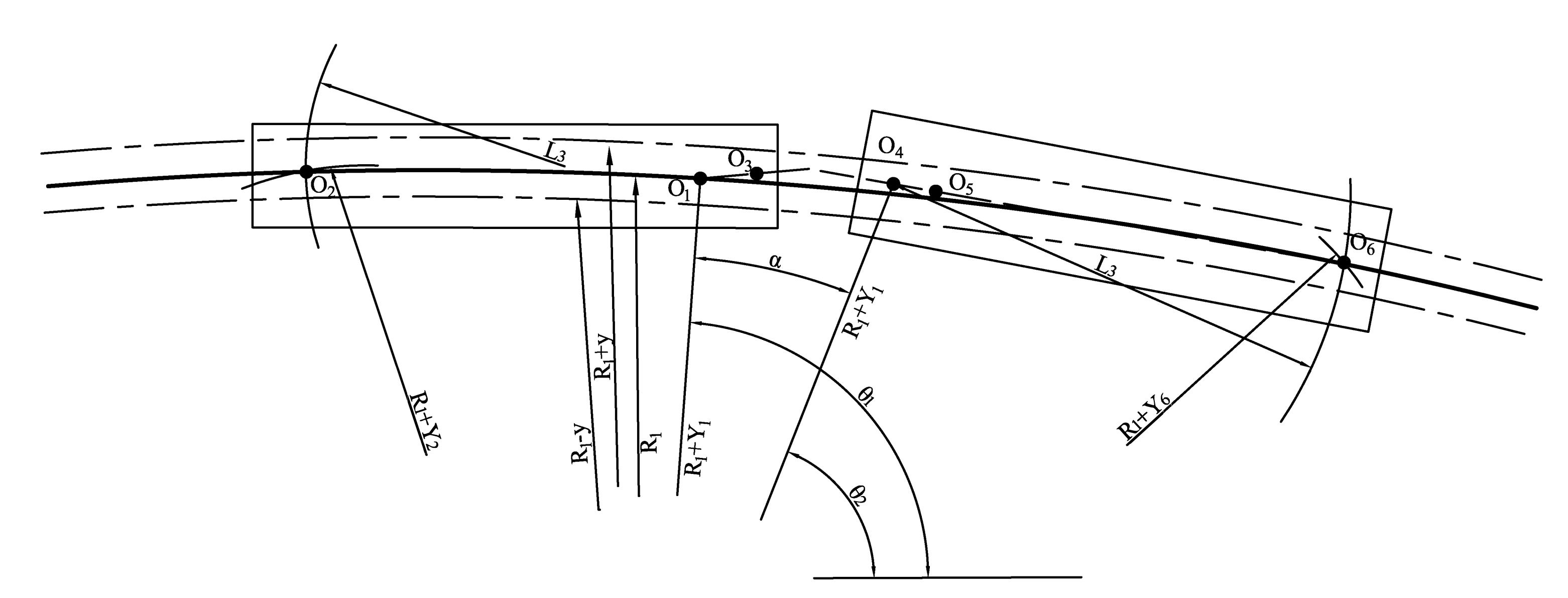
Figure 13 shows the calculation diagram of the coupler swing angle calculation method.
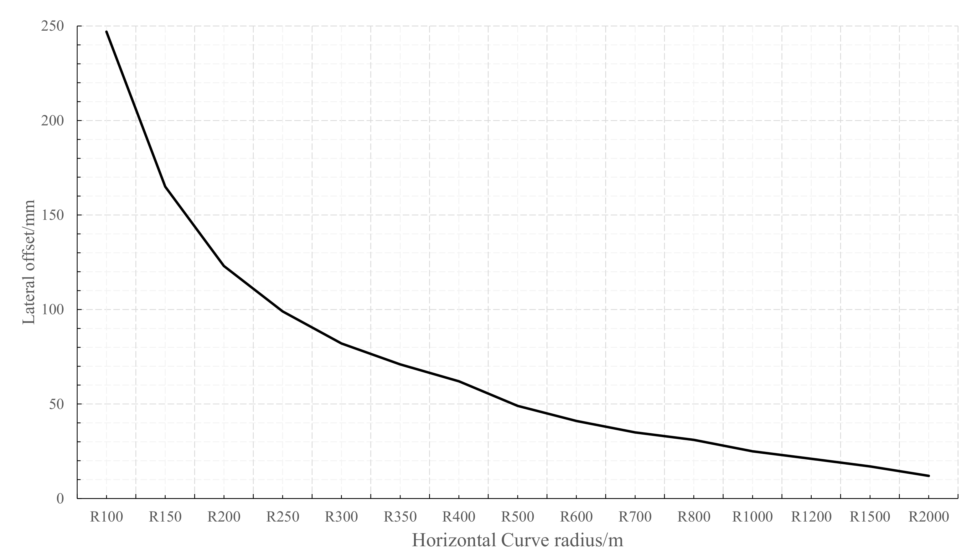
In the schematic diagram, is the radius of the curved line; y is the maximum offset of the vehicle; , is the rear position car bogie center pin; , is the front position car bogie center pin; is the lateral offset of the center pin ; is the lateral offset of center pin ; is the lateral offset of center pin ; is the lateral offset of center pin ; is the center of rotation of the rear position vehicle; is the center of rotation of the front position vehicle; is the rear vehicle bogie wheelbase; is the front vehicle bogie wheelbase; is the length of the attached hook between vehicles.
The basic procedure of the calculation is as follows:
Step 1: Establish a coordinate system with the center of the curve as the origin. The 2-position vehicle’s 1-position center pin is laterally offset by relative to the center line. The 2-position center pin is laterally offset by relative to the center line. The coordinates of are assumed to be , denotes the angle between the line and the horizontal coordinate.
Step 2: Take as the center, and make a circle with the vehicle distance as the radius. Take the center of the center line as the center of another circle, with radius . Solve the equations of these two circles simultaneously, then obtain the coordinates (,) of the intersection point of the two circles.
Step 3: Connect
and
, as the center line of the vehicle body. If 1-position coupler rotation center
is located on the extension line of straight line
, and the distance from the center pin
is
, then the coordinates (
) of the rotation center
of a coupler are:
Step 4: The 1-position vehicle’s 2-position center pin is laterally offset by relative to the center line. The 1-position center pin is laterally offset by relative to the center line. At this time, the coordinate position of needs to be estimated based on the angle between and ; assume that the coordinates of are (), denotes the angle between the line and the horizontal coordinate.
Step 5: Make a circle with center , and the vehicle distance as the radius. Take the center O() of the center line as the center of another circle with radius R + . Solve the equations of these two circles simultaneously. The coordinates of the intersection point of the two circles () can be obtained.
Step 6: Connect
and
to obtain the center line of the vehicle body. The car body extends along this line in an axial symmetry distribution. The 2-position coupler rotation center
is located on the extension of straight line
, and the distance from the center pin
is
. Then, the coordinates (
) of the rotation center
of the 2-position coupler is:
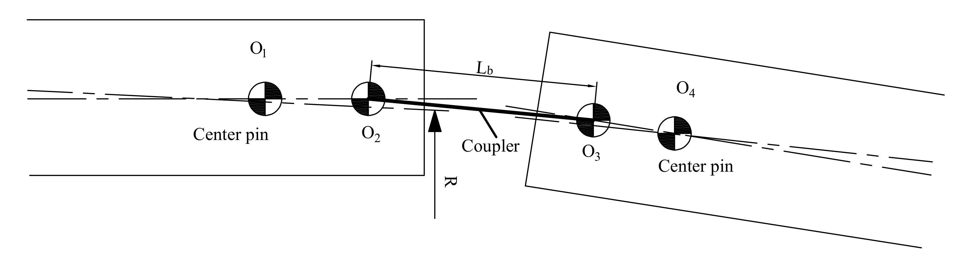
Step 7: Determine the position of the 1-position vehicle by determining the length of the coupler. First, according to the front and rear vehicle coupler rotation centers
and
, calculate the coupler length
,
Figure 14 shows the geometric schematic of the vehicle hook length calculation.
Step 8: As shown in
Figure 14, determine the threshold as
, if
, continue to Step 9 to calculate the swing angle of the coupler. If
, modify
, and repeat Steps 4 to 7 until the requirements are met. Continue to Step 9 to calculate the coupler swing angle.
Step 9: Calculate the swing angle of the coupler. Calculate the angles between the straight lines and , and the straight lines and .
4.3. Determination Method of Hook Position under Horizontal Curve
Take the example of circular curve working condition, the two couplers are successfully connected under the guidance of the guide rod after the above conditions are met.
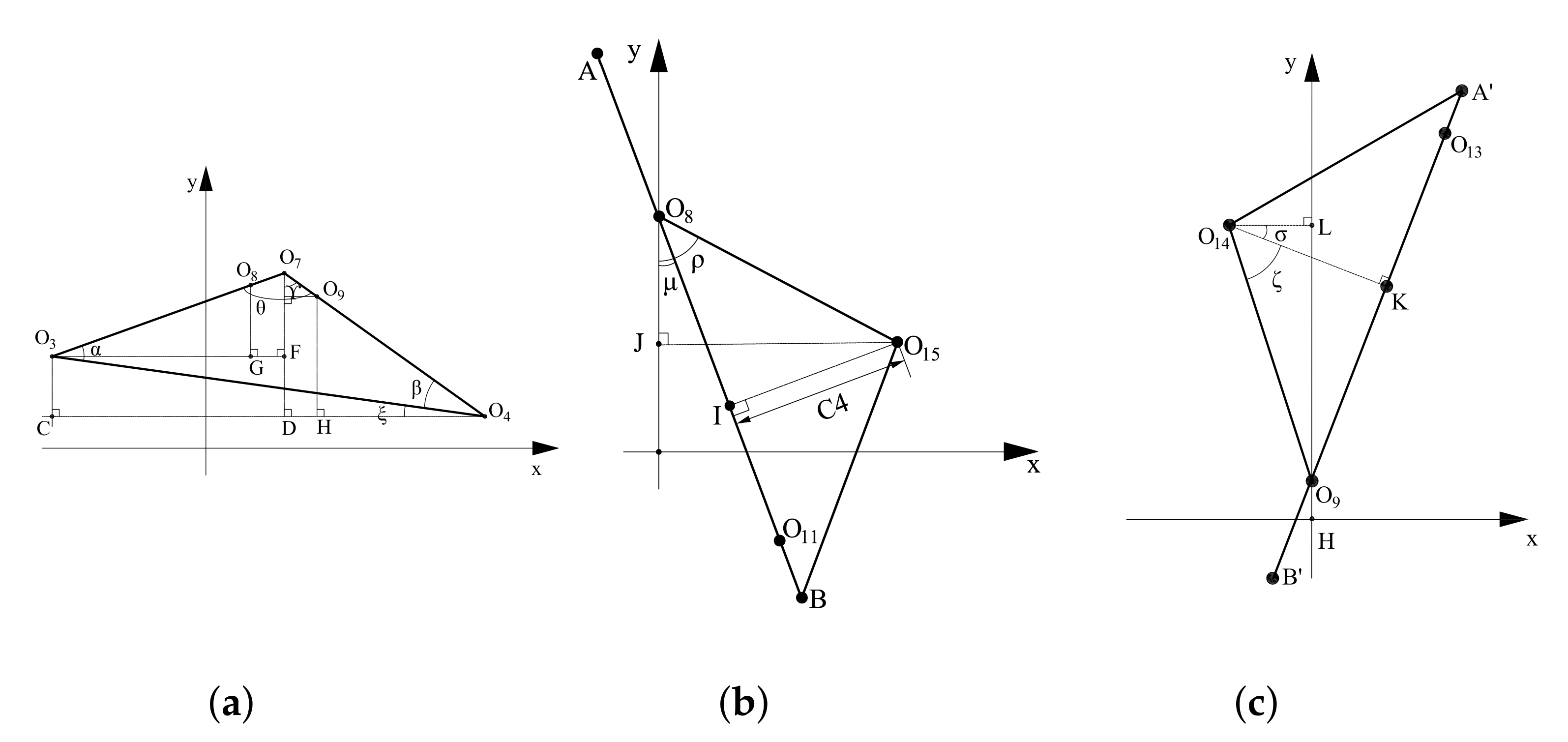
Figure 15 shows the geometric diagram of the calculation method for coupler connection.
As shown in
Figure 15, point
is the center of rotation of the hook of the No.1 vehicle and point
is the center of rotation of the hook of the No.2 vehicle;
and
are the center points of the ends of the hooks of the two carriage hooks;
is the intersection of the centerline of the hook bodies of the two hooks; the angles
and
are the front and rear hook swing angles calculated in
Section 3.3.1; the points
represent the same geometric meaning as that represented by
in
Figure 11.
Step 1: As shown in
Figure 15a, establish a coordinate system
with the center of the curve as the origin. From the vehicle body pose calculation method, the coordinates of
are (
) and the coordinates of
are (
), and the left and right swing angles are
and
after the coupler is connected.
Step 2: For connection point and point , make an extension line along the center line of the coupler through two points and . If the two straight lines intersect at a point , so that , and can form a triangle, then the next step can be calculated. Otherwise, the coupler will not be normally automatically connected and manual assistance is required.
Step 3: Make a vertical line perpendicular to the
X-axis through
, and make a straight line parallel to the
X-axis through
. The two lines intersect at a point
C, let
be
. Cross
to make a perpendicular line to cross
at point D, let
be
. Let
be
, then:
The coordinates of
(
) are:
Step 4: Make a perpendicular line passing
to intersect
at point
F, and then make a perpendicular line passing
to intersect
at point G, then the coordinates of
(
) are:
In the same way, cross
to make a perpendicular line to intersect
at point
H, then the coordinates of
(
) are:
Step 5: As shown in
Figure 15, by determining the slope of the straight line
and the straight line
, the coordinates (
) of point
and the coordinates (
) of
are obtained as:
In the same way, as shown in
Figure 15c, it can be concluded that the coordinates of point
(
) and the coordinates (
) of
are:
Step 6: As shown in
Figure 15b, cross point
to make a perpendicular line and cross AB at point
I. Cross point
to make a perpendicular line to cross
at point
J, let
be
, let
be
, then the coordinates of point
(
) are:
In the same way, cross
to make a perpendicular line
at point
K, and cross point
to make a perpendicular line to cross
at point
L. Let
be
, and let
be
, then the coordinates (
) of point
are:
Step 7: As shown in
Figure 11, when the coordinates of each point of
and
are known, the cosine value of each angle in the two triangles can be obtained:
Step 8: If the cosine values of the six corners are all greater than 0, the six corners are all acute angles, which meets the requirements for automatic coupling of couplers. If the cosine values of the six angles are not all greater than 0, the six angles are not all acute angles, which cannot meet the requirements for automatic coupling of the coupler.


