1. Introduction
With the rapid development of the information technology, people can transmit data to each other through the internet. However, plaintext transmitted in the network is very easy to access, duplicate, temper, or even destroy by malicious attackers. Thus, the concern of data transmission security emerged. Therefore, image steganography techniques, for instance reversible and irreversible data hiding, have been introduced to conceal the secret data in cover images. Currently we have, according to the technique core, data hiding schemes which can be roughly categorized into the LSB substation [
1,
2], the difference expansion (DE) [
3,
4], the histogram shifting (HS) [
5,
6], the reference matrix-based [
7,
8,
9,
10], and the pixel-value differencing (PVD) [
11,
12] approaches. Since the modification of the cover image is very subtle, the constructed marked images cannot be distinguished from the cover one visually. Therefore, these data hiding techniques have significantly enhanced the security level of data transmission.
Instead of hiding secret data in a single cover image, the visual cryptography proposed by Naor and Shamir [
13] hides secret data in multiple image shadows. Their method consists of two phases. First, in the dealing phase, a dealer divides the secret data in
image shadows and distributes the data to different participants. Secondly, in the reconstruction phase,
or more than
shadows are gathered and stacked together. The secret data can be retrieved without any error. However, the visual cryptography suffers from two problems. First, each image share looks meaningless and may catch the eavesdroppers’ attention during transmission. Secondly, the produced image shadows are larger than the secret image in scale.
Later, many different secret image sharing (SIS) schemes [
14,
15,
16,
17] have been proposed. The method in [
14] preserves the image scale and the secret image can be retrieved directly by stacking two transparencies. In [
15], the binary secret image can be gained by superimposing any
of
meaningful shadows without performing any cryptographic computation. In 2020, Harn et. al. [
17] proposed a secret image sharing scheme with a secure secret reconstruction process. In their method, the secret can be protected from both the attacks of insiders and outsiders. More specifically, the outsiders need to intercept all the released shares to recover the secret, which is impossible.
The dual-image-based reversible data hiding (RDH) scheme [
18,
19,
20,
21] can be regarded as a special case, with
, of the
secret image sharing. The first dual-image-based scheme was proposed by Chang et al. [
18] in 2007. In their method, each cover pixel pair was used to conceal two 5-base digits along the main and the anti-diagonal direction of the EMD matrix. The embedding capacity (EC) of their method was only about 1 bit per pixel (bpp). Later, an improved version proposed by Chang et al. [
19] used the horizontal and the vertical directions of the EMD matrix instead of the main and anti-diagonal directions to embed the two 5-base digits. The peak signal-to-noise ratio (PSNR) raised to 48 dB while maintaining the same EC as [
18]. In 2013, Lee and Huang [
21] developed a novel reversible data hiding scheme using two shadows, which utilized the combination of the orientations in the corresponding stego pixel pairs to fulfill the reversibility. The EC of their method was 1.07 bpp and the visual quality of the image shadow was improved to 49 dB. In 2021, Chen et al. [
20] introduced a dual-image-based RDH scheme using a EMD reference matrix. Each pixel in the cover image is embedded with
secret bits with the help of a random binary stream. Although the EC of that method is higher as 1.56 bpp, the PSNR of the constructed shadows is less than 42 dB.
The authentication ability has attracted the attention of many scholars, for instance, the original batch verification using summation polynomials [
22,
23] and batch verification based on blockchain and ECDSA technology [
24]. Nevertheless, these methods are realized with the help of a key generation system or a public blockchain center. The authentication in image domain is that a tampered shadow can be detected directly by a legal one without other assistance. The first authenticable secret sharing scheme was proposed by Yang et al. [
25] in 2007. However, the authentication ability and image visual quality of their scheme were not satisfactory. To improve the drawback of the method, Liu et al. [
26] proposed a novel (2, 2) secret sharing scheme based on the TS reference matrix in 2018. Since the modification of the cover pixel value does not exceed two, good visual quality can be guaranteed in their method. Furthermore, the difference between pairwise generated stego pixels do not exceed two either, so the cheating detection rate based on this property can reach to 95%. Later, Lin et al. [
27] proposed a novel (2, 2) secret sharing scheme with the help of the EMD reference matrix in 2019. In comparison with the method in [
28], EC and cheating detection ratio are about the same, but the visual quality of image shadows has been greatly improved. Subsequently, different secret image sharing schemes with their authentication mechanisms were proposed [
28,
29].
The disadvantage of the (2, 2) secret sharing scheme is that it needs both shadows to be gathered to extract the secret data and restore the cover image. In 2020, Gao et al. [
30] proposed a (2, 3) reversible secret image sharing scheme based on a fractal matrix. In their method, the secret data is embedded in three shadows of the cover image through the guidance of a fractal matrix. The secret data and the cover image can be retrieved by any two of the three shadows, but image distortion may occur. In this paper, we introduce an optimal (2, 3) reversible secret sharing scheme based on a crystal-lattice matrix. The advantageous features of our method are listed below:
Produce image shadows with least distortion;
Guarantee the reversibility using any two of the three image shadows;
Perform an excellent cheating detection ratio.
The rest of this article is organized as follows.
Section 2 introduces the method proposed by Gao et al. in [
30].
Section 3 presents the proposed crystal-lattice matrix and the image shadow production process in detail. Our experimental results are illustrated in
Section 4. Finally, the conclusions are summarized in
Section 5.
2. Review of Gao et al.’s Method
The (2, 3) reversible secret sharing scheme proposed by Gao et al. [
30] is composed of three steps, including the fractal matrix construction phase, the image shadow production phase, and the data extraction together with the image recovery phase, as introduced in
Section 2.1,
Section 2.2 and
Section 2.3, respectively.
2.1. Fractal Matrix Construction Phase
In the method implemented by Gao et al., they defined two types of fractal groups which are composed of four 2
2
2 fractal models and nine 3
3
3 fractal models, respectively, as shown in
Figure 1,
Figure 2 and
Figure 3. The projections of both fractal models on the three axial planes are a perfect square, as shown in
Figure 4 and
Figure 5. As shown in the figure, each location at a square projection is occupied by a unique model element. Furthermore, the same conclusion can be found in the projections of the two fractal groups on the three axial planes, shown in
Figure 6 and
Figure 7.
The fractal matrix sized 256 256 256 is constructed by arranging fractal groups consecutively along the main diagonal direction. Since the sizes of Type I and Type II fractal groups are 4 4 4 and 9 9 9, respectively, the fractal matrix contains adjacent Type I fractal groups or adjacent Type II fractal groups, where ⌊⌋ denotes the floor function. Without the loss of generality, the fractal matrix with Type II fractal model sized 3 3 3 is applied in the following description.
2.2. Image Shadow Production Phase
Based on a cover image , their scheme produces three image shadows, , , and , with the guidance of the fractal matrix. The given cover image sized is first rearranged into a pixel sequence in the raster scan order. Then, the pixels in the sequence are consecutively processed. Each time, a pixel is duplicated into a triplet (, , ) and the triplet is modified into (, , ) according to the given secret digit and the fractal matrix. The pixel values of the modified triplet are then separately recorded in the three image shadows of the corresponding spatial location.
The rules of modification are as follows. First, the triplet (
,
,
) is treated as the 3D coordinates of an element in the fractal matrix. Since the coordinates of the three axes are identical, the located element lays on the main diagonal line of the fractal matrix. Recall that if the main diagonal line is consecutively arranged with fractal groups, the located element must be within a fractal group. The index of the located fractal group can be determined by
, where
denotes the floor operation. The 9
9
9 space occupied by a fractal group contains nine main diagonal elements as well as nine fractal models. To ensure the reversibility, a one-to-one mapping between the nine main diagonal elements and the nine fractal models is preassigned. An example of numbering the fractal models is shown in
Figure 7. Thus, the target fractal model
sized 3
3
3 for data embedding can be determined by
, where
is the modulo operation. The exact target element of embedding is determined by the 9-based secret digit
, which satisfies
Finally, the shadow pixels (
,
,
) can be obtained by
A simple example is elaborated for a better understanding of the embedding phase of Gao et al.’s method. Suppose the cover pixel
and the 9-based secret digit
. The index of the target fractal group is
, and the number of the fractal model used for data embedding is determined by
. According to
Figure 7, the target fractal model located by
is
, as circled in red in 3D and 2D projected versions. To embed the secret digit
, the exact matched element is
, as shown in
Figure 5. Thus, the shadow pixels (
,
,
) can be obtained by
Finally, the shadow pixels are recorded into shadow images , , and . Notice that 9 is not a factor of 256, so four pixel values are not covered by any fractal group. In their method, the pixel values 0, 1, 254, and 255 are left intact. To simplify explanation, the pixel values 0 and 1 are not excluded from fractal groups in our demonstration.
2.3. Data Extraction and Cover Image Restoration Phase
By using any two of the three shadows, Gao et al.’s method can extract secret data and restore the cover image. Without a loss of generality, suppose shadows
and
are applied to decrypt secret data and cover image. The pixels in both images are rearranged into vector sequences
and
first. Then, consecutively process the pixel pair
,
to decrypt data. Take the pixel pair
,
as an example. Its corresponding fractal group is located by
Then, its projected coordinates in the fractal group can be obtained by
which belongs to the fractal model
. Note that the range of the
-coordinate is unique by referring to
Figure 8. The coordinates
map to model index
, whose range of
-coordinate can be further determined by referring to
or
projection. The secret digit can be extracted by applying the modulo operation
=
and mapping to the fractal model, as shown in
Figure 9. The mapped value at
of
-projection is
Finally, the cover pixel value can be restored by
Based on the 9
9
9 fractal group, a reversible (2, 3) secret image sharing scheme can be realized. Two 9
9
9 fractal groups and their projections on the
,
, and
-planes are plotted in
Figure 10, where each group contains 9 fractal models displayed with different colors. Recall that the original cover pixel triplet (
,
,
) lays on the main diagonal line. To embed secret data, the pixel values are modified into the space occupied by the fractal groups. The deviation of the target element from the main diagonal line directly influences the distortion of pixel values in the image shadows. To produce image shadows with a minimum distortion, the target elements should be arranged to the surroundings of the main diagonal line. Observe that the vicinity of the conjunction points between fractal groups are not fully exploited to embed data. It indicates that further improvement of shadow image quality is possible.
3. Proposed Scheme
The proposed reversible (2, 3) threshold secret image sharing scheme is based on the same frame structure as the fractal matrix-based scheme. The crystal-lattice matrix is proposed to address the weakness of the fractal matrix. Construction of the crystal-lattice matrix is firstly introduced in
Section 3.1, where the growth of a crystal lattice and the construction of a crystal-lattice matrix are also presented. The shadow image generation phase and the decryption phase are explained in
Section 3.2 and
Section 3.3, respectively.
3.1. Crystal-Lattice Matrix
To reduce the distortion of secret image shadows, the fundamental model associated with each element on the main diagonal line of the 3D reference matrix should be arranged closely around it. To achieve this goal, a greedy algorithm is proposed to construct an optimal fundamental model. Inspired by the growth of a crystal material, we treated the elements on the main diagonal line as the seeds for crystallization. The fundamental models are the lattices grown simultaneously and crowdedly toward the radial directions from the stream of seeds. Meanwhile, the projections of the lattices on each axial plane should be unique to meet the requirement of (2, 3)-threshold secret sharing. Subject to these constraints, the greedy algorithm is applied to append the nearest element, one at a time, to each lattice at the same relative location until the predefined range is fully searched. Suppose the seed elements are
and
is the window width of the search range. The candidate elements to be appended are
,
and
. To ensure a greedy choice that minimizes the distortion each time, the candidates within the search range are fully listed and sorted in the ascending order of Euclidean distance.
Table 1 lists the sorted processing queue of
together with their square Euclidean distance
The crystal growth Algorithm 1 is summarized as follows.
| Algorithm 1. The crystal growth algorithm |
Input: The window width , the lattice model size , the secret key .
Output: The lattice model , the crystal-lattice matrix .
- 1.
Scan the search range, sort the candidate elements in the ascending order of Euclidean distance, and list the processing queue .
- 2.
Initialize the counter and the 3D matrix sized by
- 3.
Initialize the three projection matrices , , and sized by
- 4.
Retrieve an element from . If Equations (6)–(9) hold, record to , mark the matrix elements by Equations (10)–(13), and update the counter ; else, skip this element.
|
|
|
|
|
|
|
|
|
- 5.
Repeat Step 4 until the required queue volume is satisfied. - 6.
Fill each lattice model with a random permutation of 0 to generated by key
|
The lattice model and the crystal-lattice matrix are equivalent. The former records the deviation vectors from the seed of all elements in a crystal lattice; the latter is a fully sized matrix which labels the lattice index of each matrix element. The two versions can be converted into each other through simple manipulations.
In Step 1, switching the order of scanning the elements in the predefined search range may change the queue list and the resulting output. As shown in
Table 1, the elements indexed 1 to 6 in the queue are equidistant from the seed. Switching scanning order may change the order of these elements and thus change the greedy selection. Some possible results are mutually spatial symmetric. However, this factor does not lead to significant influence on the output performance.
A fully sized matrix is created in Step 2 to record the lattice index of each occupied element. The initial value is used to indicate an unoccupied state. Three two-dimensional matrices , , and are created in Step 3 to record the projected locations of included elements. In Step 4, we check the simultaneous growth of all models by including the new greedy choice that do not overlap each other in 3D space and the projected axial planes first. When the choice is available, it is recorded to the lattice model and the labeling matrices. Note that Equation (6) is not necessary, since Equations (7)–(9) are stricter constraints.
The final volume of the lattice model is determined by the required payload of each cover pixel. When the payload of each cover pixel is bits, the final lattice volume is . A proper window width should be set to ensure a sufficient range of searching. A slightly oversized window width is alright.
Table 2 lists the set of deviation vectors for the lattice model with
. The 3D view of its corresponding crystal-lattice matrix together with projections on the three axial planes are provided in
Figure 11. The embeddable elements are translationally symmetric duplications of the crystal-lattice model along the main diagonal line. The distribution is approximately a cylindrical shape, as expected. In addition, the projection views demonstrate the uniqueness at each location. As shown in the figures, the elements of a crystal lattice are not connected. An element that violates any of Equations (7)–(9) is not available for embedding. This strict rule results in a sparse distribution of the lattice elements.
Recall that a lattice model is the embeddable space of its corresponding seed element. Before the crystal-lattice matrix can be applied as the 3D reference matrix for data embedding, a random permutation of distinct integer values from 0 to should be assigned to the elements of each lattice model. The random permutation can be determined by a secret key shared in advance.
3.2. Shadow Image Generation
As mentioned above, the proposed data hiding scheme shares the same scenario as the fractal matrix-based scheme proposed by Gao et al. in [
30]. The system diagram of the new proposed scheme is shown in
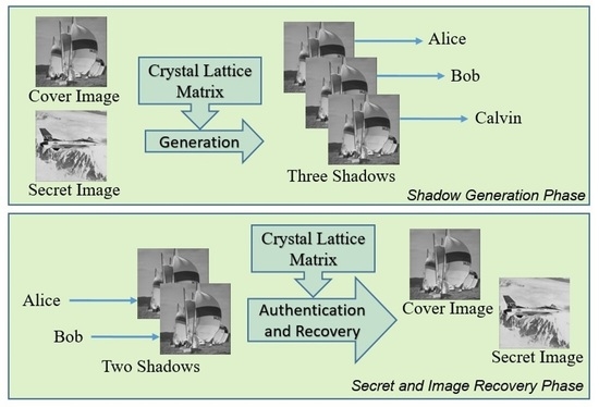
Figure 12. Through the cover of a regular image, three indistinguishable data-embedded shadows are generated and separately distributed to three participants. Any two participants can cooperate to decrypt the secret data and the cover image losslessly. When all three shadows are available, the third shadow can be exploited to check the integrity of these shadows. The shadow generation Algorithm 2 is given as follows.
| Algorithm 2. The shadow generation algorithm |
Input: The cover image , the binary secret stream , the parameters , , and the key .
Output: Three image shadows , , and .
- 1.
Construct the crystal-lattice matrix according to , , and the key . - 2.
Convert into -ary number sequence . - 3.
Rearrange into a sequence in the raster scan order. - 4.
For each pixel in , do
If ,
Retrieve a secret digit .
Find subject to
Record to , , , respectively.
Else
Record to , , , respectively.
End- 5.
Terminate Step 4 when the secret sequence is exhausted. - 6.
Copy the remaining cover pixel values to the image shadows directly and close all files.
|
The notation represents a translated lattice model , whose seed element is To further elaborate the key process in Step 4, an example has been provided. Suppose the cover pixels are , , , and the secret digits are . The detail of processing the three cover pixels are as follows.
- (1)
Pixel : This pixel value is not within the range of , it is not embeddable and the duplications are recorded to , , , respectively.
- (2)
Pixel
: This pixel value belongs to the embeddable range, a secret digit
= 7 is retrieved from
. The translated lattice model
is the group of red elements displayed in
Figure 13a, whose projections on the three axial planes are displayed in
Figure 13b–d. Its seed element valued
is squared in blue in the projection views. Since the secret digit to be embedded is
= 7, the element
, circled in yellow, is the targeted. The pixel values
are recorded to
,
,
, respectively.
- (3)
Pixel
: This pixel value also belongs to the embeddable range, the next digit
= 5 is retrieved from
. The translated lattice model
is the group of yellow elements displayed in
Figure 13. Its seed element valued
is squared in blue in the projection views. Since the secret digit to be embedded is
=5, the element
, circled in red, is the targeted. The pixel values
are recorded to
,
,
, respectively. The resulting shadows are
,
,
3.3. Secret Decryption, Image Recovery, and Authentication
Recall that any two shadows among the three can decrypt the secret and restore the cover image for a (2, 3) threshold RSIS scheme. Without a loss of generality, suppose the shadows and are available; the following Algorithm 3 can be applied to decrypt the secret digits and restore the cover image.
| Algorithm 3. The secret decryption and image recovery algorithm |
Input: Two image shadows and , the matrix parameters , , the key .
Output: The cover image , the binary secret stream .
- 1.
Construct the crystal-lattice matrix according to , , and the key . - 2.
Create the projection matrix and fill in the element values by referring to . - 3.
Rearrange and into pixel sequences and in the raster scan order. - 4.
For each pixel pair in and , do
If and ( or ),
Record to .
Else
Find the secret digit and the cover pixel value by |
|
|
Record the secret digit to ; record to
End- 5.
Convert into the binary secret stream .
|
The notation represents the projection of onto the -plane. The example secret image shadows and are applied to demonstrate the key process of Step 4. Three pixel pairs , , and are consecutively processed as follows.
- (1)
Pixel pair : This pixel pair is constituted by equal value pixels and the value does not belong to the embeddable range. Therefore, record the value to the output image directly.
- (2)
Pixel pair
: By using
as the coordinates of
, refer to
Figure 13b, the secret digit can be obtained by
. In addition, the seed element of the
is
. Therefore, the cover pixel value
is recorded to the output image.
- (3)
Pixel pair : Similarly, by using as the coordinates of , the secret digit can be obtained by . The seed element of the is . Therefore, the cover pixel value is recorded to the output image.
In the process of secret image generation, pixel values are in fact the spatial coordinates of the model elements. Recall that the crystal-lattice models are all seeded at the main diagonal line of the crystal-lattice matrix. Therefore, the embeddable elements are confined around the line. By leveraging data integrity of the image shadows, we can authenticate a suspected shadow based on a faithful share. Suppose we hold the faithful shadow . The authentication of the suspected shadow is given in Algorithm 4.
| Algorithm 4. The authentication algorithm for two image shadows |
Input: Two image shadows and , the matrix parameters , , and the key .
Output: Authentication report.
- 1.
Construct the crystal-lattice matrix according to , , and the key . - 2.
Create the projection matrix and fill in the element values by referring to . - 3.
Rearrange and into pixel sequences and in the raster scan order. - 4.
For each pixel pair in and , do
If and ( or ),
Current pixel passed.
Else
If , current pixel passed, |
|
Else Authentication failed and program stop.
End- 5.
Image shadow authentication passed.
|
Based on the same concept, we can devise an authentication algorithm for three image shadows. Since the secret binary stream and the cover image can be restored with two secret shares, the pixel values of the additional third share are uniquely determined. The data integrity of three shares provides a strong restriction to detect tampered shadows. The authentication for three image shadows is given in Algorithm 5.
Note that the two authentication algorithms are both based on the data integrity of image shadows. The tampered shares can only be detected based on faithful shares. When we only get a faithful share in hand, Algorithm 4 can be applied first to check data integrity. In case the integrity check is failed, we can detect the tampered share by using Algorithm 5. However, the detection rate of the two-shadow version is slightly weaker, which will be further discussed in the next section.
| Algorithm 5. The authentication algorithm for three image shadows |
Input: Three image shadows , , and , the matrix parameters , , and the key .
Output: Authentication report.
- 1.
Construct the crystal-lattice matrix according to , , and the key . - 2.
Rearrange , , and into sequences , and , and in the raster scan order. - 3.
For each pixel triplet in , , and , do
If and ( or ),
Current pixel passed.
Else
If , current pixel passed, |
|
Else Authentication failed and program stop.
End- 4.
Image shadow authentication passed.
|
4. Experimental Results
This section demonstrates the performance of the proposed scheme by some simulations. The programs are all implemented by MATLAB R2017b software running on a MacBook Pro (Retina, 15-inch, Late 2013) computer. The macOS High Sierra operating system is loaded in the computer, and its CPU and RAM are 2.3 GHZ Intel Core i7 and 16 GB, respectively. Eight standard grayscale test images of size 512
512 are applied in our experiment, as shown in
Figure 14.
Commonly, the PSNR, defined in Equation (18), is exploited to evaluate the quality of the generated shadows.
where
, defined in Equation (19), is the mean square error between the cover image and the compared shadow.
where
W and
H are the width and the height of the images.
and
are the pixel values at the location
of the cover image and the shadow, respectively.
The metric EC, defined in Equation (20), is the embedding capacity measured in bits per pixel (bpp),
where
represents the total length of embedded secret stream and
is the number of shadows. Although three image shadows are generated, the restoration of secret data and cover image requires only two shares. We apply
to calculate EC in the following experimental data.
4.1. Visual Quality of Image Shadows
The matrix parameter
controls the volume of the lattice model
and thus determines the embedding capacity. To embed integer number of secret bits for each cover pixel, we apply the values
,
, and
in our experiments. According to Equation (20), EC values are
,
, and
, respectively. The average PSNR values of the three image shadows, over the eight test images, are listed in
Table 3. As the value
increases, the visual quality of image shadows degrades. Besides, the average PSNR values of three shadows are not the same. The worst case for
,
, and
are
,
, and
, respectively. Note that the PSNR value is calculated from the deviation of modified pixel-value. By referring to
Table 2, we can obtain the four leading entries that applied in the case of
, where the maximum deviation
occurs at
. That is why the worst PSNR occurs at the shadow
. The other cases can be explained in the same way. Recall that the scanning order of candidate elements may alter the queue sequence; thus the resulting list in the lattice model can affect the PSNR relationship of three shadows.
4.2. Comparison with Gao et al.’s Scheme
In this subsection, we compare our scheme with the (2, 3) threshold secret image sharing scheme proposed by Gao et al. [
30]. In their scheme, two fractal models sized
and
are provided. The two models comprise four and nine embeddable elements, respectively. Fortunately, the volume of our lattice model is adjustable. To make a fair comparison, we set the same volumes and calculate experimental data as listed in
Table 4 and
Table 5.
As shown in the tables, the visual quality of image shadows produced by our scheme outperforms Gao et al.’s scheme with a gap about 3 dB. The improvement, as expected, can be explained by referring to
Figure 10 and
Figure 11, where the embeddable elements are distributed in lumped shapes and in a uniform cylindrical shape, respectively. In addition, the total embedded bits are also listed in the tables. Due to different solutions for the boundary problem of 3D reference matrices, the total payload of the proposed scheme is slightly greater than Gao et al.’s scheme.
4.3. Authentication
In this section, we conduct a series of experiments to verify the applicability of the proposed Algorithms 4 and 5 for authentication, which are based on the integrity check of two shadows and three shadows, respectively. The secret image shadows are generated with a lattice model of .
Verification of Algorithms 4: A demonstration of two-shadow authentication is given in
Figure 15. By using image Boat as the cover image, the shadow generation algorithm produces three image shadows. Suppose we hold a faithful shadow
, as shown in
Figure 15a, while shadow
has been tampered with a window region replaced by image Cameraman, as shown in
Figure 15b. The tamper detection result by applying Algorithm 4 to the shadows
and
is displayed in
Figure 15c, where black pixels in the window region fail to pass the integrity check. Only a small portion of pixels displayed in white has passed.
Verification of Algorithm 5: A demonstration of two-shadow authentication is presented in
Figure 16, where real shadows
,
and tampered shadow
are displayed in
Figure 16a–c, respectively. The tamper detection result by applying Algorithms 5 is displayed in
Figure 16d.
The detection rate (DR) to evaluate the performance of integrity check is defined by
where
denotes the total number of tampered pixels and
denotes the number of detected ones. To investigate the performance of our authentication algorithms, the detection rates for the eight cover images are listed in
Table 6. The DR value is above 90 percent for the two-shadow version and above 99 percent for the three-shadow version. The high DR value is not surprising, since the embeddable elements just occupy a small portion of the 3D crystal-lattice matrix. As the volume of lattice model increases, the DR value slightly decreases. Nonetheless, in any case, it is almost impossible for a tampered shadow to pass the authentication algorithms.
4.4. Comparison with Other Related Schemes
In this section, we compare the features of the proposed scheme with other different secret image sharing schemes, including Chang et al.’s scheme in 2014 [
10], Chang et al.’s scheme in 2020 [
28], and Li et al.’s scheme [
29]. As shown in
Table 7, the schemes proposed in [
10] and [
28] use multiple cover images, and these cover images cannot be recovered after extracting secret data. While the proposed scheme and Li et al.’s scheme [
29] use a single cover image to generate multiple image shares, the cover image can be recovered by the recipient. Besides, our new scheme provides two versions of authentication. When the third faithful shadow is available, the detection rate of our scheme is the highest among all. Even if one of the three shadows is not available, the proposed scheme can still reach a cheating detection ratio of 95 percent.
4.5. Time Efficiency
Table 8 shows the execution time for the embedding and extracting phases of our scheme when
P is set as 4 and 9. The execution time is less than 0.2 s for the embedding phase and less than 0.4 s for the extraction phase. We can conclude that the proposed scheme is computationally efficient and suitable for real time applications.
4.6. PDH Analysis
The pixel-value differencing histogram (PDH) is a histogram which is constructed based on the frequency of the difference between every two adjacent elements in an image. For a natural image, the PDH should exhibit a peak at the zero-difference value and gradually descend outward as the blue curves, as shown in
Figure 17. The PDH of four cover images together with their corresponding shadows are plotted in
Figure 17, where the high embedding mode of
P = 9 is applied. Obviously, the normal PDH shape of a natural image is well preserved for all the image shadows.


