1. Introduction
The electricity distribution systems are typically unbalanced because of the continuous change in customer loading profile during the day. Once the three phases are not adequately balanced, the risk of over-loading in the network equipment and the power losses increase. Subsequently, the system stability is affected, the supply quality is decreased, and the electricity cost is increased [
1]. On the other hand, load balancing improves the reliability and security of the electrical network. Load balancing also minimizes system losses to relieve transformer loading [
2,
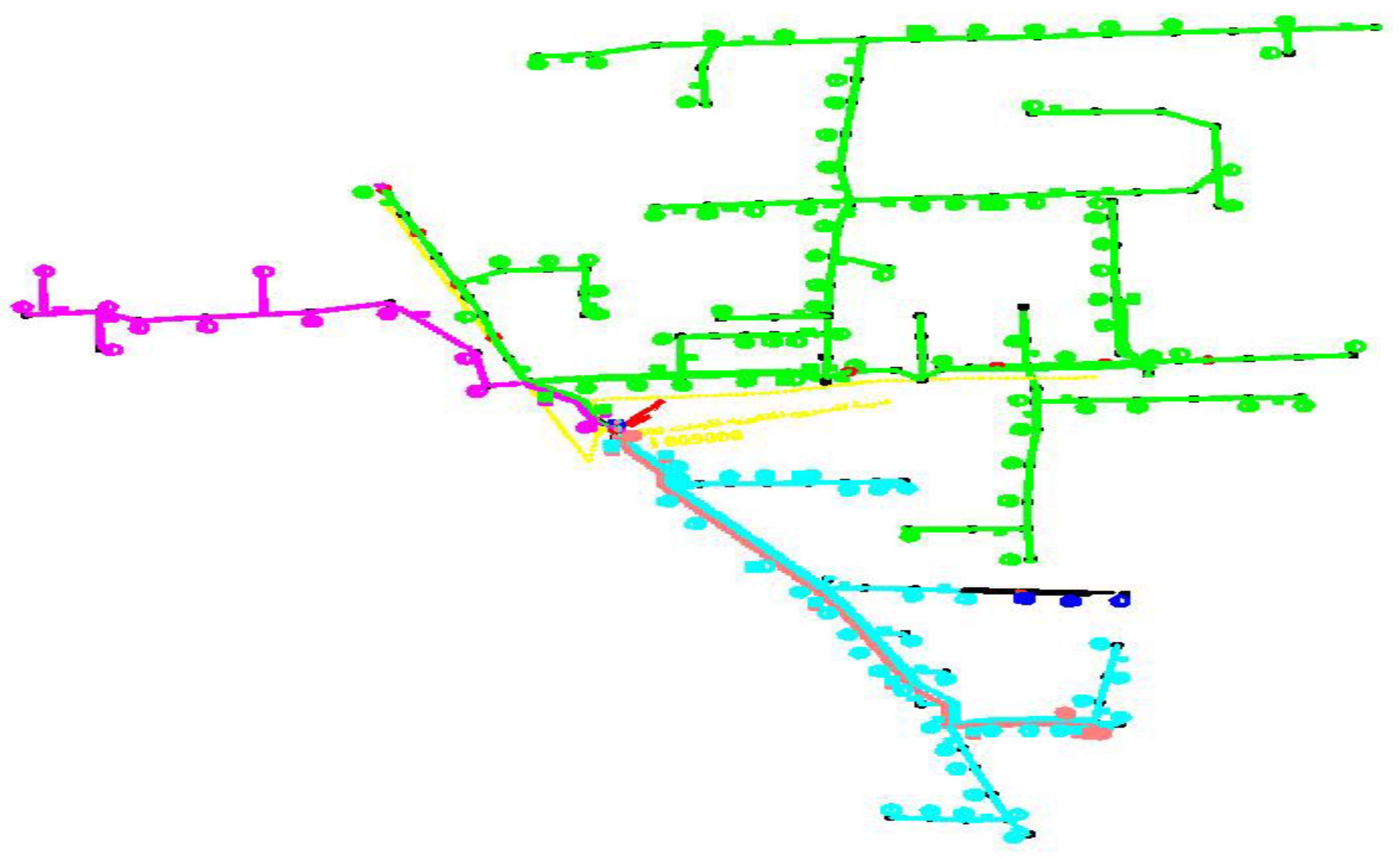
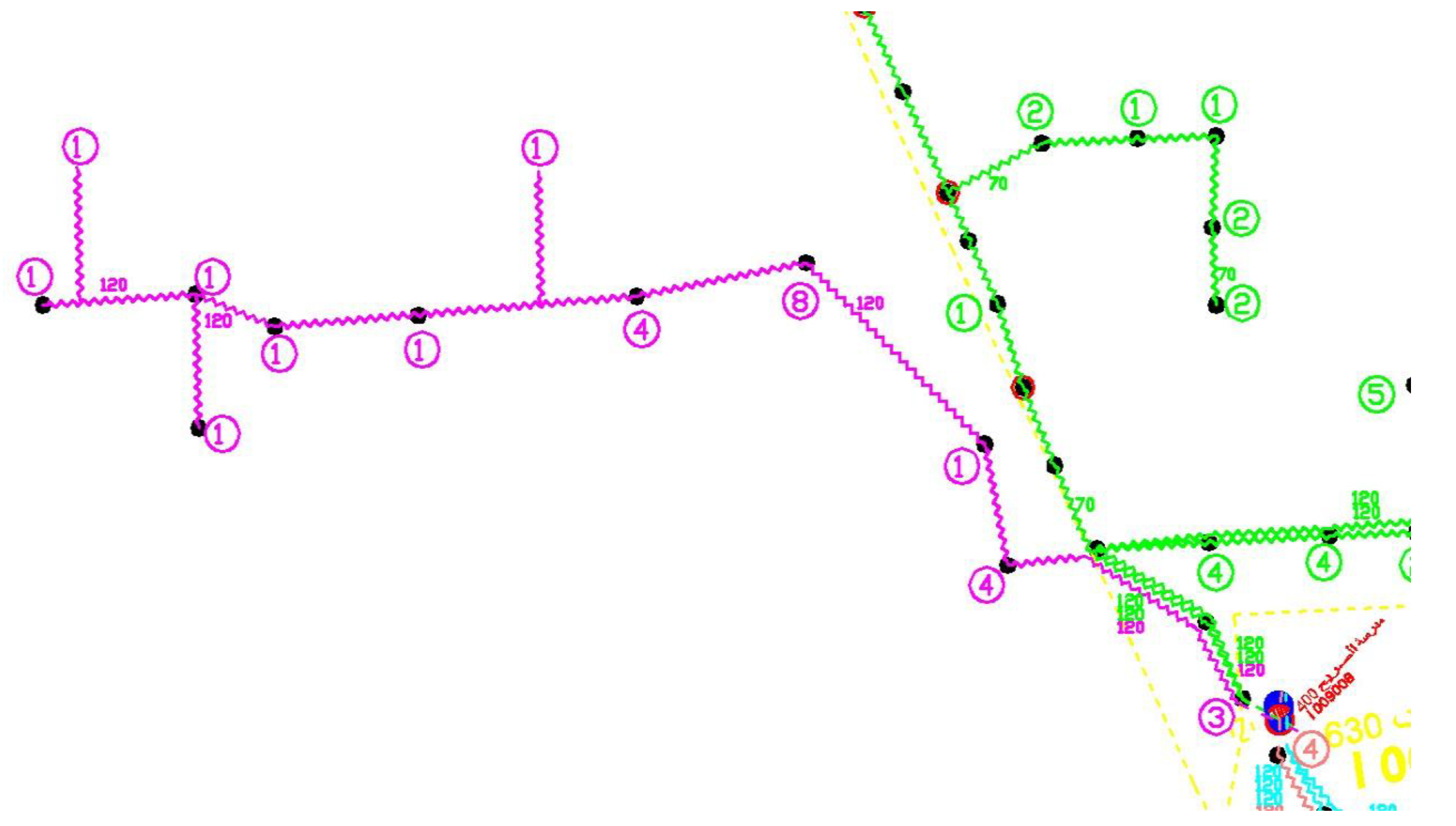
3]. Imbalanced three-phase feeders can be reconfigured by implementing some load balancing techniques such as phase swapping and feeder reconfiguration. The phase swapping technique changes the distribution of loads by swapping them between the phases to make the three phases as equal as possible without changing the feeder topology, as shown in
Figure 1 and
Figure 2, respectively. Data obtained from the smart meters which are installed at the beginning of each low voltage feeder and customer side are sent directly to the remote controller (brain) to calculate the losses on the feeder. Feeder losses are computed as a difference between the feeder and the summation of the customers’ consumption. After that, the controller gives orders to a one-way switching device to take action—if needed—to swipe between the phases feeding customers. Data sent to the controller can be classified into fixed data and variable data, as shown in
Figure 3. Fixed data can be introduced as the data regarding the network topology, such as cable lengths, sizes, and configuration, and customer data such as customer numbers at each connection node. While the variable data are the data that come from the main smart meter fixed at the beginning of the low voltage feeder containing power and energy, and the data coming from the smart meters fixed at the customer side, containing the power and energy consumption, as well.
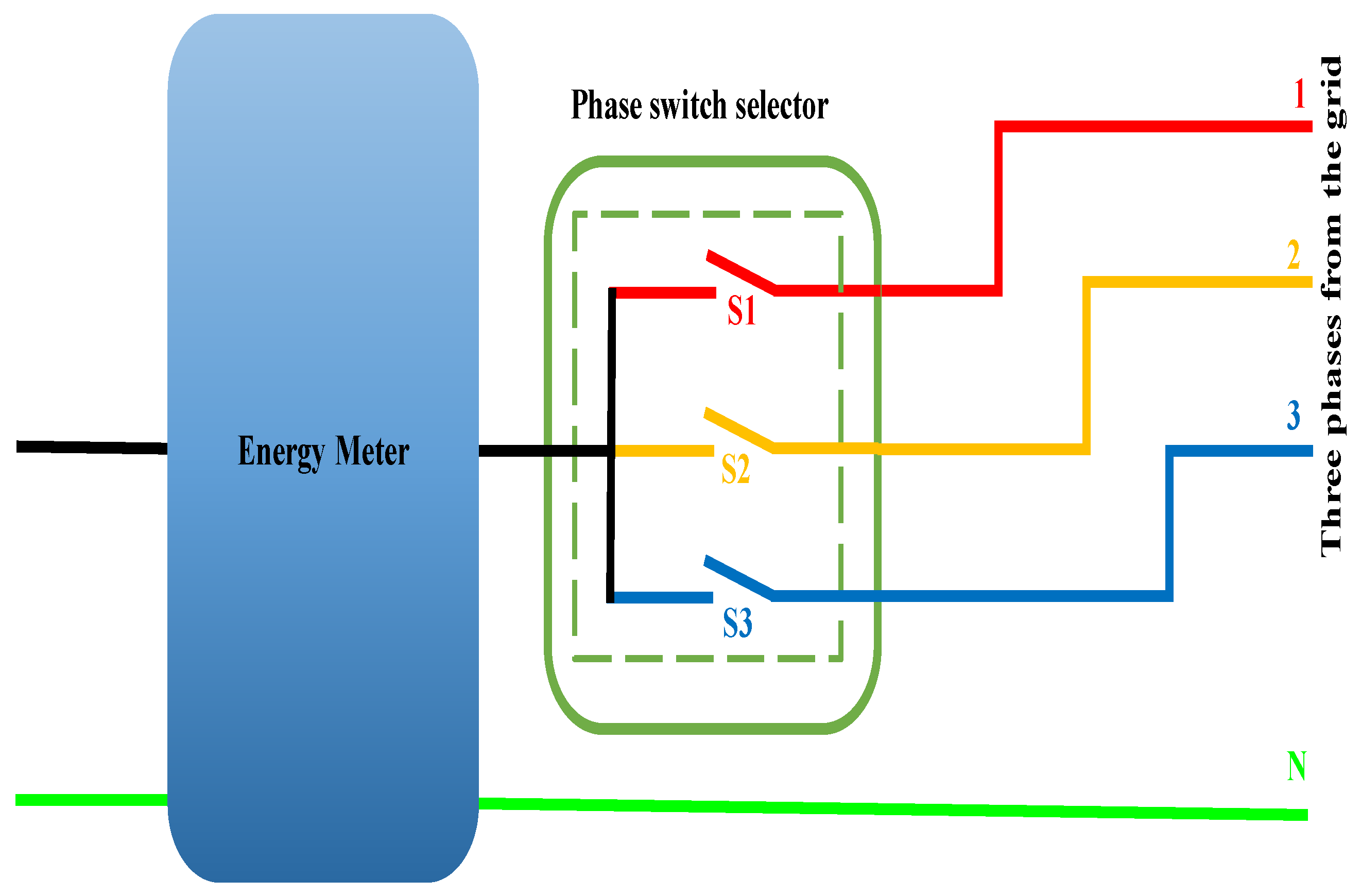
This mechanism is implemented using a phase switch selector/controller installed right before the energy meter at the customer side and swapping the customers between the three phases on the same feeder to maintain continual phase balancing. When three phases are connected to the phase switch selector’s input side, only one switch should be closed as an output, while the other two phases should remain open, as shown in
Figure 4.
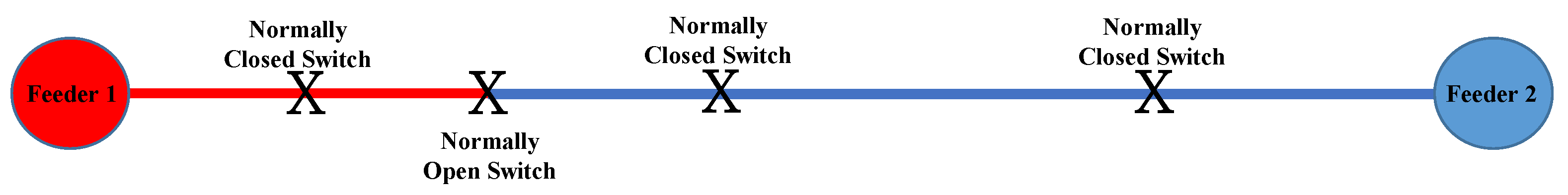
The feeder reconfiguration technique changes the feeder topology by moving parts of the feeder to an adjacent one by changing the switches’ status so that loads are switched from one feeder to another to relieve the loading of an overloaded feeder to a lightly loaded one [
4,
5]. Usually, feeder reconfiguration shifts the loads from the heavily loaded feeder to another lightly loaded feeder. Practically, electricity distribution utilities perform load balancing with manual trial and error technique, which is time-consuming, costly, and does not guarantee phase loading equality. Phase balancing automation becomes more realistic, resilient, and agile. It is implemented through power electronics, modern communication techniques, and artificial intelligence. Different types of neural network-based approaches are presented in this work to control the switch selector output to swap customers between the phases. Along with the low voltage distribution feeders, several customarily opened and normally closed switches are distributed to allow transferring load currents between the feeders [
6].
Distribution systems operate under constraints to assure the continuity of supply to the customers under certain quality. The distribution feeders consist of a variety of loads under different categories. This variation in load types and their peak demands do not coincide. Therefore, a variation in loading on some parts of the feeder during the day is noticed. Hence, it is essential to reconfigure the network by rescheduling the loads to operate the system effectively [
7]. Feeder reconfiguration modifies the topology of the distribution system by changing the open and close status of switches to better the distribution networks, whereas phase swapping changes the customer connection from one phase to another. The load balancing analysis determines which loads can be reconnected to different phases. Load balancing in the distribution system is defined as preserving the load currents roughly identical to the three phases. Loads are considered evenly distributed on the three phases; i.e., each phase should be connected to
of the total loads. So, the problem is to find the most appropriate three sets of loads, with minimum differences among the individual sums of the three sets.
The loss minimization in distribution system reconfiguration and load balancing problems of the open-loop radial power are presented using different techniques such as heuristic or meta-heuristic approaches [
8,
9,
10], mathematical programming [
11], and intelligent algorithms [
12,
13]. The heuristics techniques produce acceptable results with less computation cost. The network reconfiguration with optimal distribution generators siting, sizing, and tie-switch placement for reliability improvement and loss minimization is proposed [
14]. The loss minimization using reconfiguration and switching modifications like closing or opening the sectionalizing switches of the distribution feeders are manipulated. A three-phase load balancing using load flow variation technique before electrical installation is presented [
15,
16]. Load balancing estimation using balancing index calculation is formulated as a non-linear optimization problem with an objective function [
17]. Reducing the feeder unbalance using a fuzzy logic is demonstrated [
18,
19]. Different techniques are carried out to maintain the load balance, such as Ant Colony Optimization [
20], support vector machines [
21,
22], and discrete passive compensator [
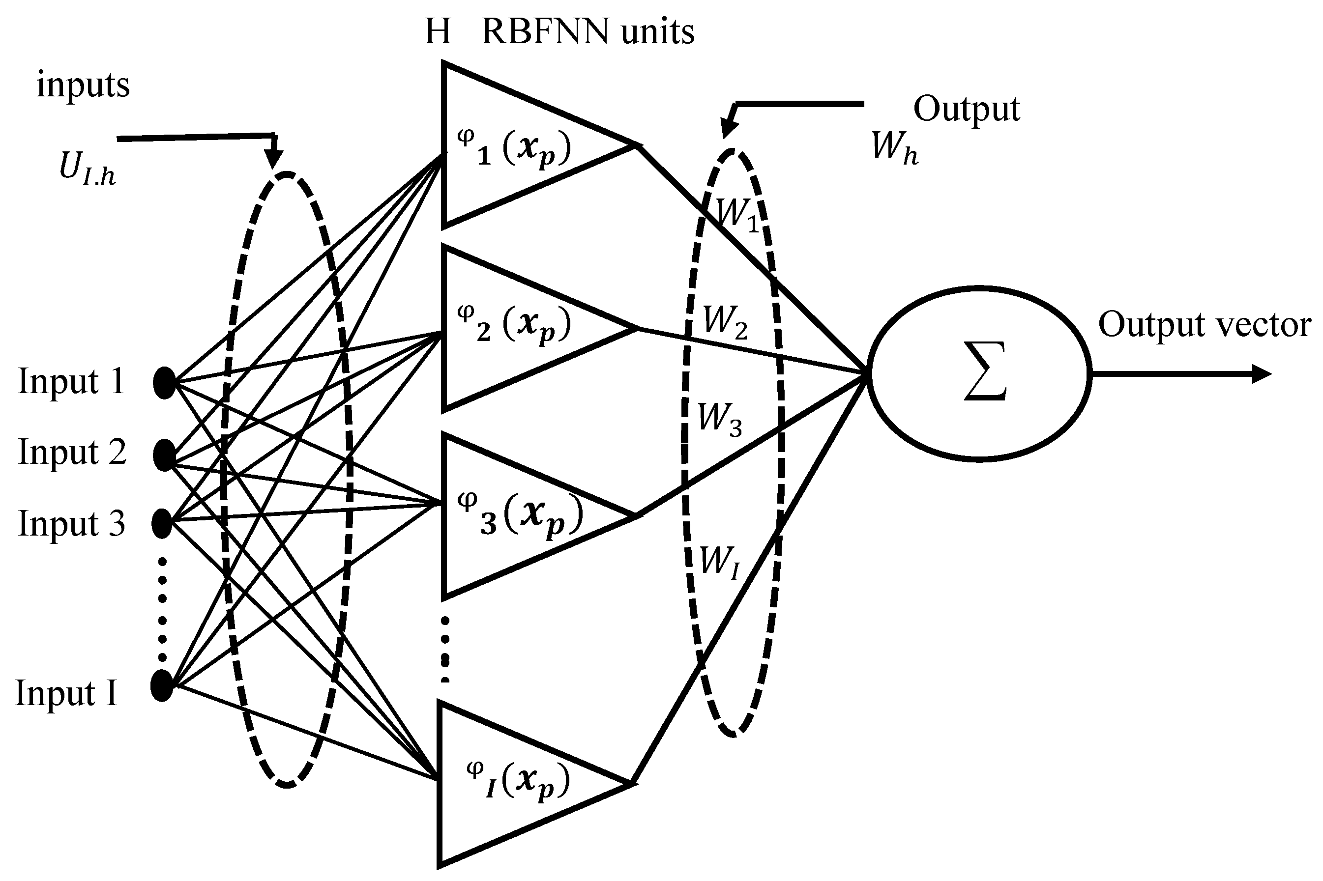
23]. This work is a real case study for an optimal automatic feeder reconfiguration using three-phase load balancing based artificial neural network (ANN) techniques: radial basis function neural network (RBFNN) [
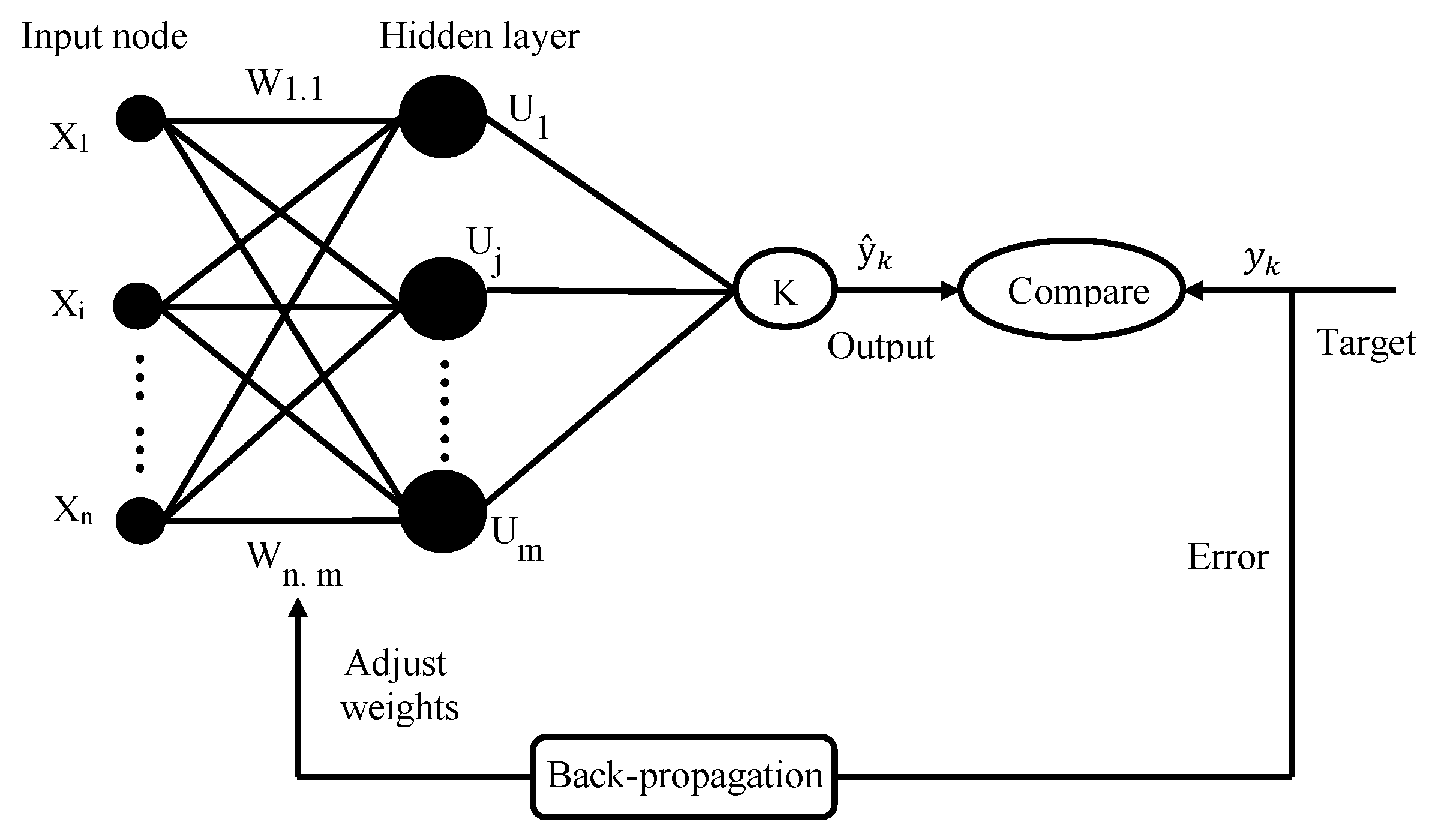
24], feed-forward back-propagation neural network (FFBPNN) [
25], and a hybrid. Implementing a hybrid technique is the original contribution. This technique enhances the learning process of FFBPNN, rides over the local minima, speeds the slow rate error convergence, and reforms classification precision.
The rest of this article is organized as follows.
Section 2 discusses load balancing. Next, the system techniques under study is presented. ANN techniques are discussed, including RBFNN, FFBPNN, and hybrid techniques are addressed in
Section 4. Results and discussion are discussed in
Section 5, followed by a conclusion in
Section 6.
2. Load Balancing
Distribution network operators face continuous pressure to improve the quality of supply for customers and decrease operating losses. Unbalanced loading of distribution feeders is one of the essential factors affecting low voltage networks’ overall losses. The asymmetry factor is high when the overall loading is low, and the asymmetry is significantly smaller during peak load. It means the system is extensively trying to symmetrize the load during the periods with low loading and minimal effect on the overall losses. Thus, the unbalanced loading of the three-phase feeder’s distribution and the impact of unbalance currents on the overall losses are considered a hot topic. Electrical utilities modernize power generation and distribution systems. The electric grid transformation offers improved performance and growth opportunities for customers, communities, and businesses. The system deployed in this study is considered the first step towards advanced metering infrastructure that integrates smart meters, software, data centers, and communication networks. Electric companies can enhance their customer services and operations.
The problem is about determining the switches that be opened or closed to obtain load balancing among feeders. Many constraints should be kept, such as voltage drop, thermal constraint, reliability constraint, and capacity constraint of distribution lines and transformers to achieve equal phase loading. The load is dynamic during the day due to the customer’s behavior and usage of their appliances. Hence some phases are lightly loaded during a certain period of the day and heavily loaded at another time.
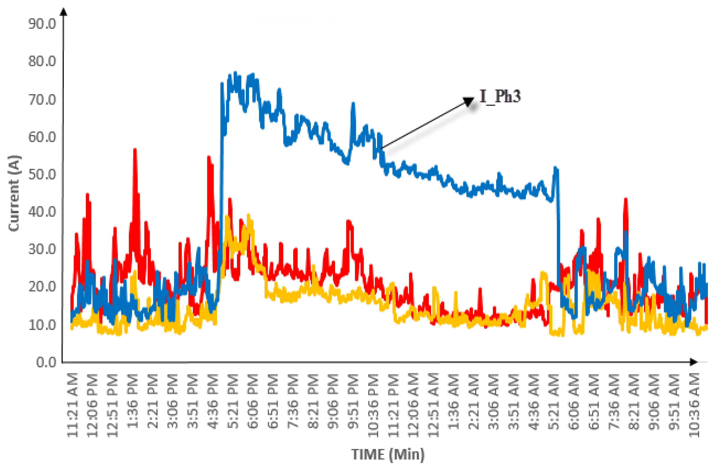
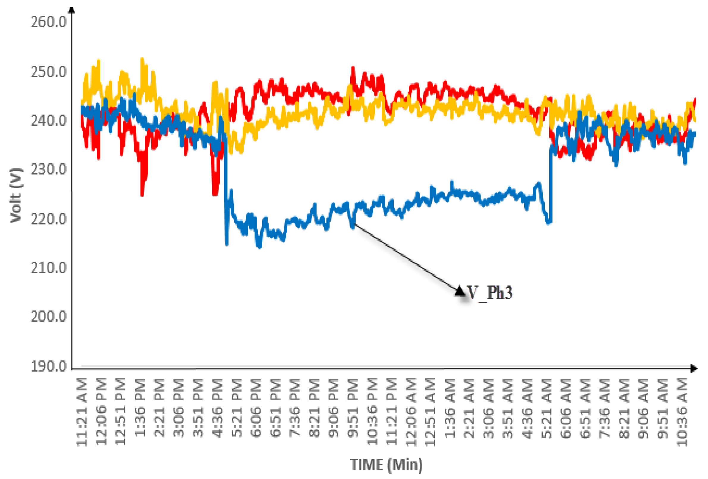
Figure 5 and
Figure 6 show an example for the unbalanced three-phase loads currents and voltages, respectively. This load is a pure residential load located in Ajlun district. Customers are swapped between the phases continuously to achieve load balancing on the feeder and the transformer. When the smart meters’ data are sent to a remote server, it starts to check through optimization techniques if there is any better arrangement for the customers on the three phases to obtain load balancing. If yes, orders are sent to the phase switch selector to swap the customer between phases, with a super-fast action to avoid supply discontinuity. Otherwise, the current situation is the best customer arrangement, and it does nothing [
26].
The phase switch selector takes an order from a remote server that collects data from the downstream smart energy meters, calculates the losses at the current situation, and rearranges the loads using one of the proposed algorithms to guarantee the best phase balancing and minimum losses. The new configuration is sent to the phase switch selector to be implemented. Thus, the phase switch selector takes a three-phase input from the grid; each phase is connected to a switch. One switch of those three switches is closed, while the other should remain open. When an order comes from the server to swap the connected customer from phase A to phase B, a super-fast switching is made to open the switch connected to phase A and close the switch connected to phase B. Discontinuity of supply would not affect the customers because it should be super-fast switching according to the phase switch selector characteristics. This fast-switching time should be mentioned in the datasheet of the phase switch selector and should be fast enough that the customers’ appliances would not affect it [
27].
3. System under Study
In Jordan, distribution feeders are a three-phase, four-wire system. Usually, they are radial or open-loop structures with the same conductor size along the feeder. Balancing loads on a three-phase feeder and reducing neutral current, improving voltage profiles, reducing losses and enhancing system stability and reliability is a very sophisticated task for the utility and engineers because they do not have authority or monitoring over their customers. Practically, phase balancing is carried out manually by trial and error technique based on experience and engineer’s knowledge about customer’s behavior in that area. By using this manual trial and error method, supply interruption is inevitable when exchanging customers’ connection phases to another.
A real case study from IDECO (latitude: 32°33
20.02
N, longitude: 35°51
0.00
E) is considered in this work. One of four radial feeders going out from a 630 KVA transformer in the Irbid district is chosen. The feeder under this study has 27 customers, is 470 m in length, and has a 120 mm
cross-sectional area. Smart meters are installed along the feeder at the customer side. Their consumption varies from 0.2 kW to 5 kW.
Figure 7 shows a schematic diagram for the transformer and the corresponding low voltage network of the four feeders coming out of it, including the feeder under study, while
Figure 8 shows a schematic diagram for the same feeder understudy and the number of customers connected to each node. The number of customers equally on the three-phase is not necessary for load balancing, but the current equality on the three phases. In some countries, almost all residential customers have a three-phase connection, but this method is used for single-phase.
5. Results and Discussion
The performance of the proposed model is evaluated, different evaluation measures have been adopted, including mean absolute percentage error (MAPE), mean squared errors (MSE), and the root means squared error (RMSE).
MAPE: It shows the deviation of the predicted errors that show how much the predicted points are close to the target line, represented by Equation (
17).
MSE: It is the average of the magnitude of the predicted errors, presented by Equation (
18).
RMSE: It shows the deviation of the predicted errors that show how much the predicted points are close to the target line, represented by Equation (
19).
where
n is the number of observations,
.
is the measured value, and
is the forecasted value. The simulation is executed on an Intel Core i7-8750H CPU, 2.20 GHz, 64.0 GB RAM computer. The proposed ANN is implemented using Mathworks/MATLAB. Different ANN techniques are used, selecting the appropriate number of hidden layers and the number of neurons is the most critical step. This step leads to quick training speed, reduced memory space, and acceptable global generalization capability. The main drawback of an inappropriate number of hidden nodes may be over-fitting for the input data. The ANN technique is used to solve the load balancing problem. There are around 10,000 samples used as real data obtained from IDECO. Each sample holds current measurements for 27 different loads (houses). It is used to control the switching sequence of each load to keep the three phases balanced. The recorded data are distributed as follows: training set
, validation set
, and testing set
. The ANN inputs are the unbalanced 27 load currents, and the outputs are the switch sequences for each load. The network’s output is in the range of (1, 2, 3) for each load. It means the phase number on which switch should be closed or opened for that specific load. The balanced output loads are obtained from implementing a heuristic technique, and they are used to train, test, and validate the ANN. A Matlab/Mathworks command (newff) is used to implement FFBPNN for the whole feeder with an input and output matrices are (10,000
and
10,000), respectively.
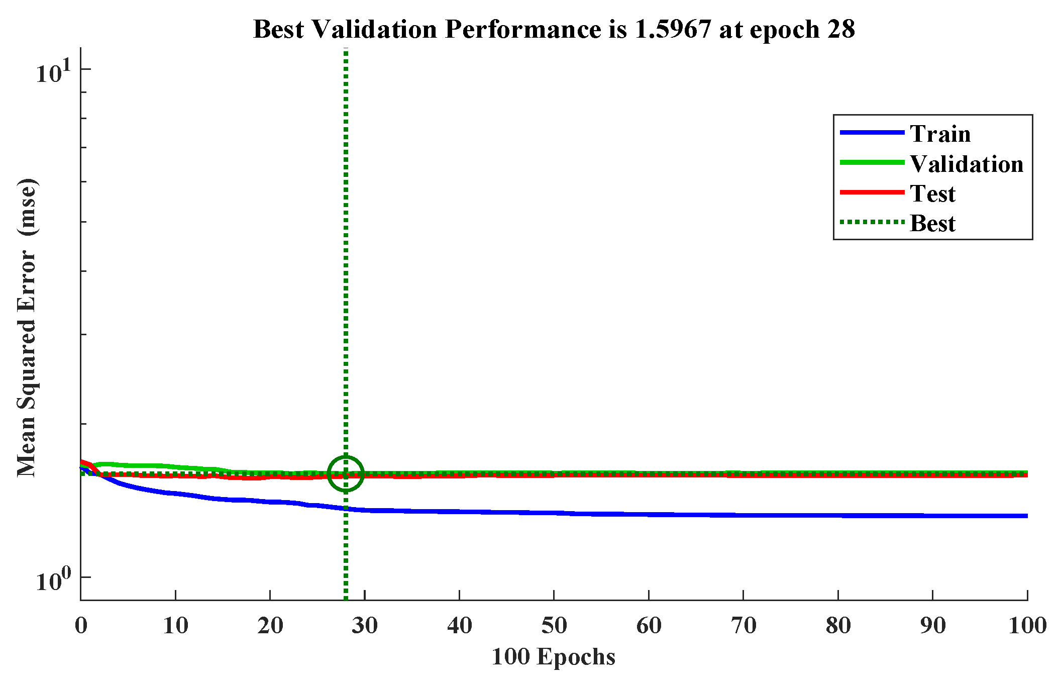
Figure 14 shows the best validation performance for FFBPNN.
Table 1,
Table 2 and
Table 3 evaluate
MAPE,
MSE, and
RMSE errors, respectively for 10,000 current samples for
,
, and
using FFBPNN for different layer architecture and different iterations (10,100,1000). For example, the first row (10-10-10) means that there are three hidden layers. Each hidden layer contains ten neurons. The optimal performance belongs to the configuration 2000, which means one hidden layer with 2000 neurons. Error evaluations for this technique failed in the load balance test, and therefore it is not recommended in such cases. The distribution of the currents on the three phases was far from the actual currents, and the rate errors were not acceptable.
Table 4,
Table 5 and
Table 6 evaluate the average error current in terms of spread constant and the number of neurons for 10,000 samples on
,
, and
, respectively using RBFNN. The configuration (5:1000) has optimum evaluation in terms of
MAPE,
MSE, and
RMSE. The errors were
, 3274, and
for phase 1,
, 3560, and
for phase 2, and
, 3274, and
for phase 3, respectively.
Table 7,
Table 8 and
Table 9 evaluate errors for the three phases using the hybrid technique. This technique has much better results than the two individual techniques in terms of performance and errors calculations.
The configuration (5:1000) has optimum evaluation in terms of
MAPE,
MSE, and
RMSE errors. The results were
, 664, and
for phase 1,
,
, and
for phase 2, and
,
, and
for phase 3, respectively. It is highly recommended for three phases of electrical load balance.
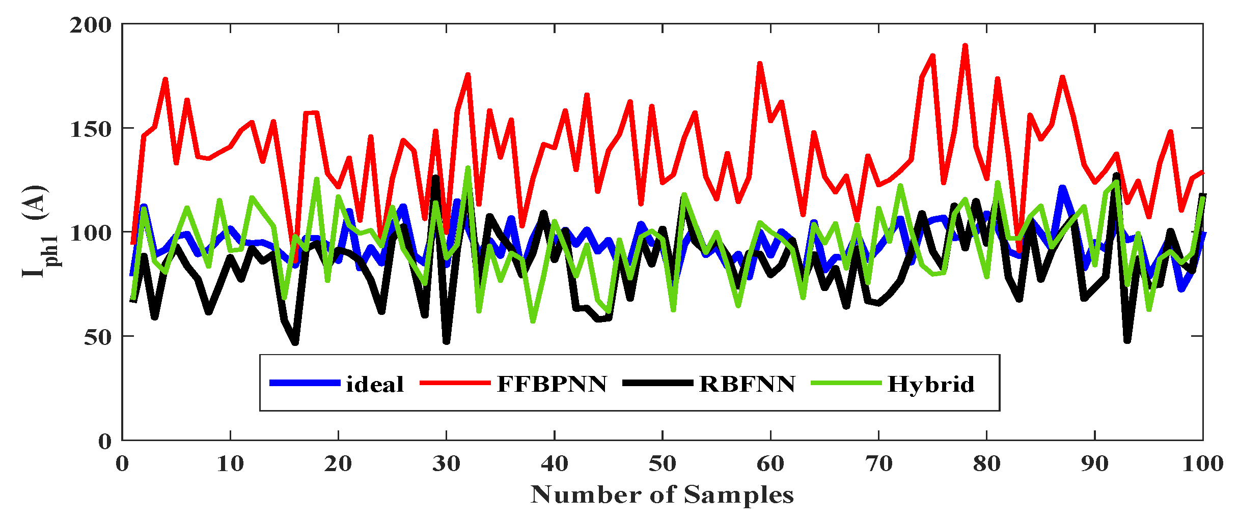
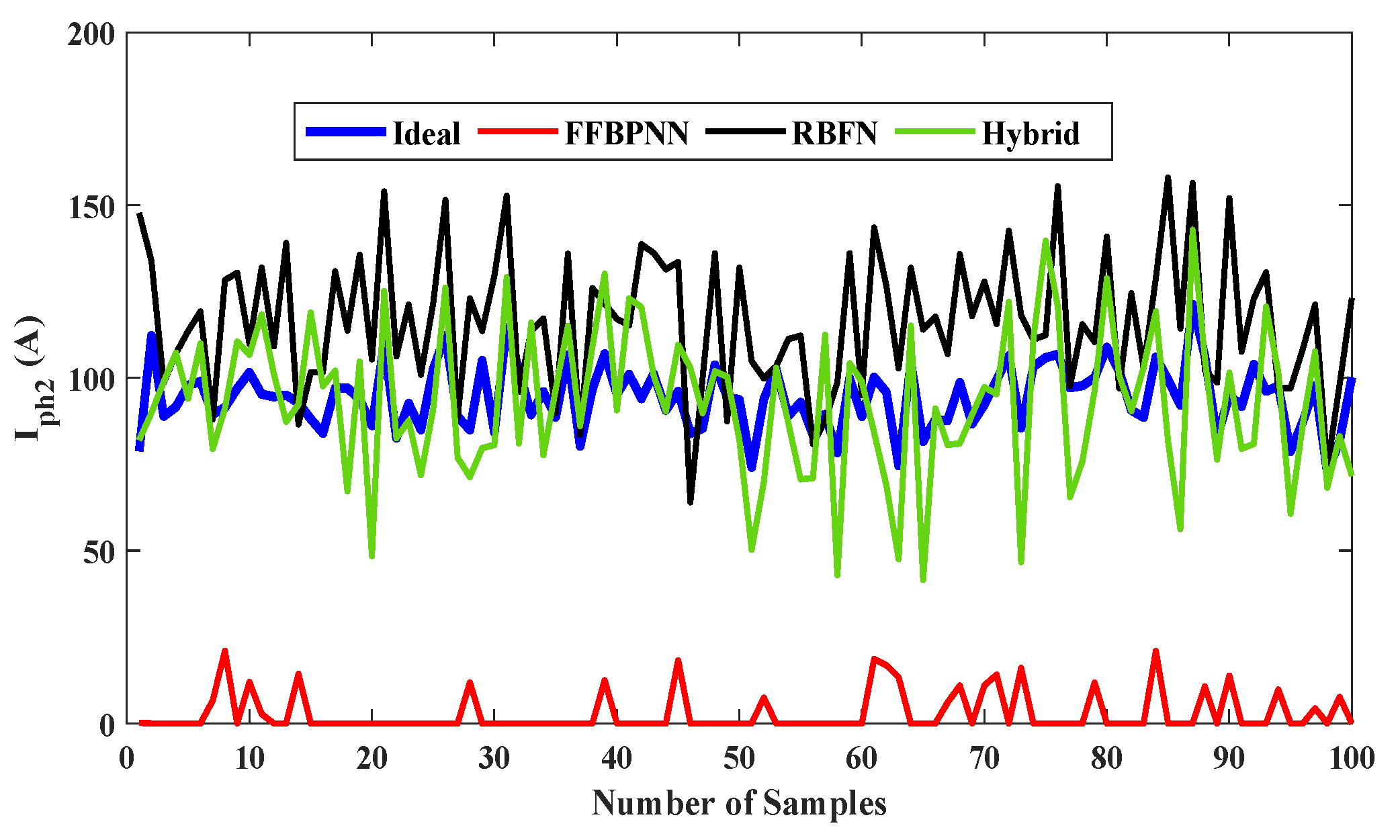
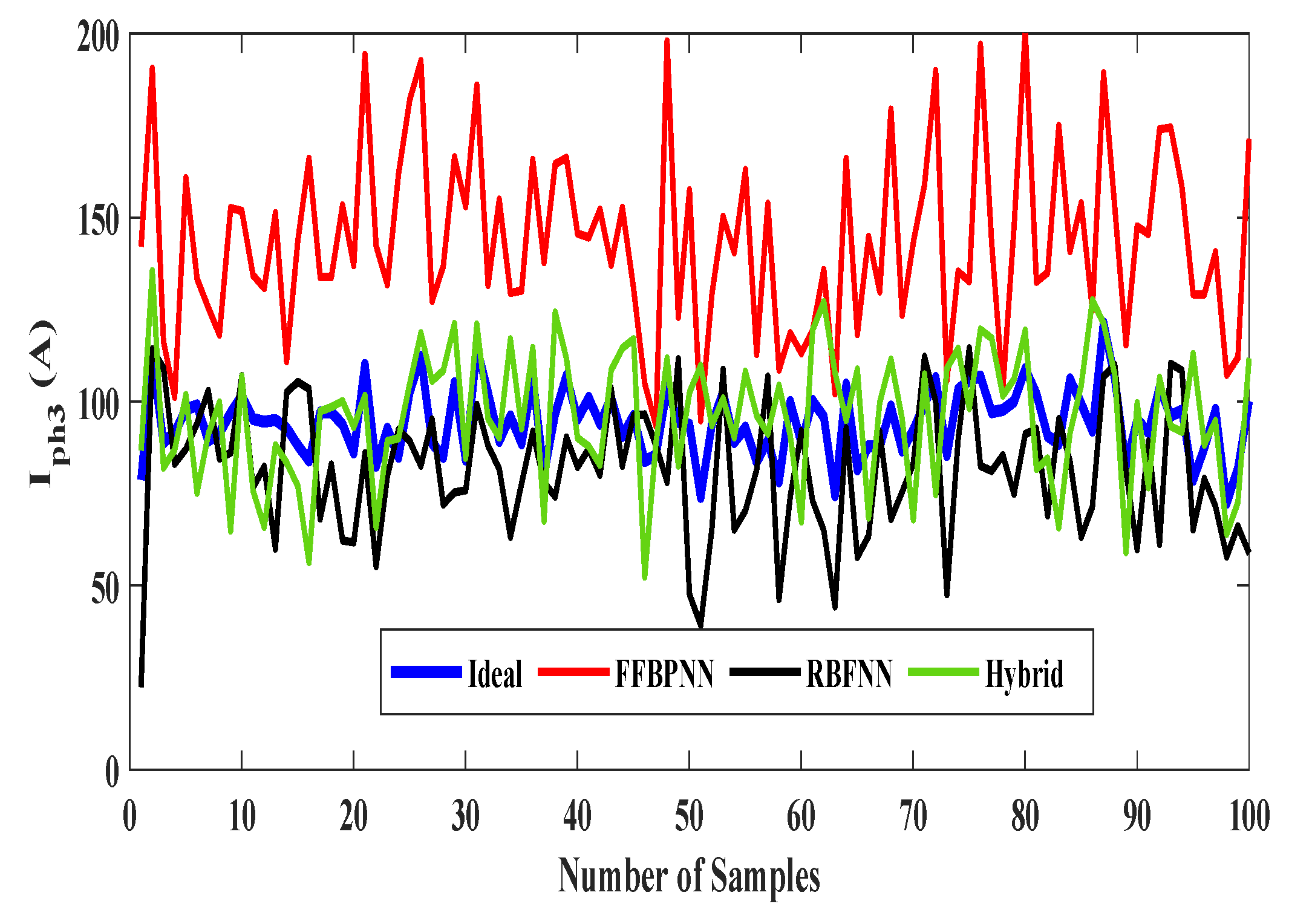
Figure 15,
Figure 16 and
Figure 17 show the three phases currents via
for the three techniques. Hence, the hybrid technique has the best performance in phase balancing studies. It is practical, flexible, and recommended to IDECO.


