Review

Optical Fiber Sensors for Monitoring Railway Infrastructures: A Review towards Smart Concept

1
School of Civil Engineering, Central South University, Changsha 410075, China
2
School of Civil Engineering and Mechanics, Lanzhou University, Lanzhou 730000, China
*
Authors to whom correspondence should be addressed.
Symmetry 2021, 13(12), 2251; https://doi.org/10.3390/sym13122251
Submission received: 16 October 2021 / Revised: 18 November 2021 / Accepted: 23 November 2021 / Published: 25 November 2021
(This article belongs to the Special Issue Symmetry in Applied Mechanics Analysis on Smart Optical Fiber Sensors)

Abstract

:
Railway infrastructures have played a critical role to ensure the continuity of goods and passenger transportation in China. Under extreme loading and environmental conditions, railway structures are vulnerable to deterioration and failure, leading to the interruption of the whole transportation system. Several techniques have been used for the health monitoring of railway structures. Optical fiber sensors are the widely recognized technique due to their inherent advantages such as high sensitivity, anti-electromagnetic interference, light weight, tiny size, corrosion resistance, and easy integration and network configuration. This paper provides a state-of-the-art of optical fiber sensing technologies and their practical application in railway infrastructures. In addition, the strain transfer analysis of optical fiber sensors is described for parameter reflection. A smart concept for artificial intelligence contribution is also declared. Finally, existing and future prospects on smart concept-based optical fiber sensors for railway infrastructure are discussed. The study can provide useful guidance to understand the problems in artificial intelligence which contributed to the Structural Health Monitoring system of railway structures.

1. Introduction

Railway infrastructures have played a critical role to the local economy by ensuring the continuity of freight and passenger transportation. Currently, railway and high-speed railways (HSR) have become the modern transportation in moving huge amounts of passengers and freight. The recent progress on train speeds and carriage tonnage are the major consideration that responsible for strength degradation of such structures. In addition, engineers have recently built expensive infrastructures for newly developed high-speed trains, which require continuous health monitoring for safety concerns. Moreover, potential hazards such as extreme natural disasters (high magnitude and frequency earthquakes, repetitive floods, landslides, etc.), human-made errors and aging effects can cause potentials risks or problems to the railway transportation systems. These factors can significantly deteriorate the performance of the railway structures that make them vulnerable, cause disruption to rail operation and endangers passengers’ life as well as freight safety [1,2,3]. Common damages observed in railway structures include accumulative strain deformations, track buckling, surface deformations, displacements, damaged components, cracks, and so on [4,5,6]. Disastrous failure of important rail infrastructures such as railway bridges, tunnels, track components (sleepers, slab, turnouts and crossing), railway station etc., may occur due to the extension of the aforementioned damages, leading to fatal accidents. Therefore, significant maintenance work and accurate monitoring are deemed necessary to guarantee the safety of railway operation and extend the lifespan of railway infrastructures [7,8].
Structural health monitoring (SHM) has been introduced as a useful tool in railway industries, aiming to manage railway assets by giving feedback on the health state of railway components. In addition, SHM increases the reliability of the structures [9], reduces maintenance costs by early detection of damages during the lifespan of railway infrastructures [10]. Conventional approaches have been used for monitoring railway infrastructures. For example, track circuit has been invented to prevent derailment on railroads [11], laser scanning and photogrammetry have been employed to monitor a set of masonry arches [12], and reliability-based analysis has been implemented for maintenance improvement [13]. Other traditional sensing techniques/devices, such as accelerometers [14,15], acoustic emission [16,17,18], magnetic sensors [10], strain gauges [19], inclinometers [20], and digital image correlation (DIC) [21], have been commonly employed. However, these approaches fail to fulfill the demand for low-cost, stable, long-term and high-accuracy performance monitoring of modern railway infrastructures. Some techniques such as DIC suffers from bulky and complexity of sensing equipment, thus, not practicable for long distance monitoring. To overcome these challenges, affordable and reliable devices are considered for monitoring railway infrastructures.
Optical fiber sensors (OFS) offer enormous advantages over conventional and other smart sensors due to their high-sensitivity, good electromagnetic resistance, small size, easy to be embedded into materials, short to long distance measurement, and so on. Recently, OFS have been widely deployed in civil engineering in a wide range application to monitor railway parameters such as temperature, strain, displacement and vibration. Recently, OFS technology is moving rapidly towards smart concept for providing useful life-cycle information to evaluate the health state of structures from their conception to decommission [22]. Progress on optical fiber sensing technology lately has offered advantages, such as long-term monitoring, long-distance measurement, early detection, high accuracy, static and dynamic measurements, and high measurement range. The geometry characteristics of OFS allow them to be easily integrated into structural materials, particularly into fiber-reinforced polymer (FRP) composites to develop smart FRP-based structural components [23,24]. Due to the fragility of OFS, packaging measures are taken to shield the sensing fiber from being damaged. However, the sensing characteristics of the sensors depend on the choice of the packaging method as the deformation from the monitored components are transferred through the packaging material to the sensing fiber. Strain transfer errors are induced by the packaging material, which can be corrected by conventional calibration tests. However, the calibration tests are not accurate to interpret the relationship between the host material and the sensing fiber for some sensors such as the embedded cases. The accuracy of the sensing system can be improved by considering the strain transfer analysis [25]. Besides, by declaring the interfacial interaction with mechanical analysis, strain transfer theory can be expected to reflect the structural parameters.
Despite recent progresses in monitoring the physical parameters of railway infrastructures with OFS, the following challenges have been highlighted: (1) a comprehensive review on OFS technologies and their application for monitoring railway infrastructures have not been sufficiently published in literatures. (2) The issues related to strain transfer analysis on railway parameters measurement have not been addressed yet. (3) The prospects of Smart concept and artificial intelligence (AI) to achieve reliable and long-term monitoring of railway infrastructures have not been considered yet.
Therefore, this study reviews the existing researches and recent advances in OFS to measure and monitor railway parameters, aiming to offer guidelines for engineers to understand the technologies of OFS and appropriately select the sensors. In addition, this study identifies the current technical challenges on smart concept and AI contribution in the SHM system.
The rest of the paper is ordered as follows: Section 2 introduces existing optical fiber sensing technologies. Section 3 reviews the applications of industrialized OFS for railway parameters measurement. Section 4 discusses the strain transfer analysis on OFS for parameter reflection of railway structures. Section 5 reviews some smart concepts of OFS for AI contribution in monitoring system of railway infrastructures. Section 6 summarizes the conclusions with some future prospects on railway monitoring based on OFS highlighted.

2. Optical Fiber Sensing Technologies

OFS technologies have seen significant progress in the last years. Several OFS sensors have been developed for multiple applications. Optical fiber sensing techniques used for civil and railway infrastructure monitoring are classified into three categories: In-Fiber Grating optical sensors, interferometry-based sensors, and light scattering-based sensors [26]. The first two categories are more suitable for local point measurements with multiplexing advantages, while the last category is appropriate for continuous and long distance measurement.

2.1. Grating-Based Sensors

In-gratings are formed in the core of optical fibers when exposed to UV-light source. Grating-based technology helps detect the effect of the gratings, which serve as a narrow band mirror for a traveling light. The gratings will either transmit or reflect the wavelength of a light source, commonly named as Bragg wavelength. The variations of strain, temperature, and vibration due to the surrounding environment shift the Bragg wavelengths of grating-based sensors. There are three available in-fiber grating-based sensors: tilted fiber Bragg grating, long period fiber grating and fiber Bragg grating (FBG) [27]. FBG sensors are the most frequently used in SHM system. Figure 1 shows the schematic and principle of a fiber Bragg grating sensor.
In FBG sensor, the reflected wavelength known as Bragg wavelength (λB) is expressed by:
λB = 2nΛ,
where λB represents the central wavelength of FBG at strain or temperature free stage, n is the effective refractive index and Λ is the grating period of optical fiber.
The deformation of FBG sensors causes a shift in the Bragg wavelength (ΔλB) due to the effect on the induced refractive index and grating period from strain and temperature changes. The central wavelength shift of an FBG sensor is given by Equation (2).
Δ λ B λ B ε , Δ T = α ε ε + α T Δ T ,
where αε is the strain sensitivity coefficient and αT are the temperature coefficient of the FBG sensor [28].
The main principle to interrogate the FBG sensor lies in decoding the wavelength-encoded information in the reflected Bragg grating. Several interrogation techniques of FBG sensors have been proposed and could be classified into three categories: passive detection schemes, active detection schemes and other schemes [29]. Update wavelength interrogator devices allow to scan 38 FBG sensors in each channel such as the F610A [30]. FBG sensors have been extensively used to accurately capture strain and temperature parameters. The main issues of using FBG sensors are their packaging, limitations for long distance sensing applications, and the need for temperature compensation. Temperature compensation and packaging methods have been addressed by several authors [31,32,33].

2.2. Interferometry Based Sensors: Mach–Zehnder and Fabry–Perot

The Mach–Zehnder based sensors use the principle of Mach–Zehnder interferometry. Beam splitters split a single light-source into two collimated beams, as shown in Figure 2a. The intensity of the phase shifts between the beams is measured. Equation (3) expresses the optical phase delay (in radians) of a passing light through a fiber [34].
ϕ = nkL ,
where n is the refractive index of the fiber core, k means the optical wavenumber in vacuum (2π/λ, λ stands for the wavelength), and L represents the length of the fiber. The differentiation of Equation (3) gives the small changes in the phase delay, expressed as:
d ϕ ϕ = d L L + d n n + d k k ,
Mach–Zehnder-based sensors are widely used in narrow space to detect gas and fluid pressure changes, as well as temperature change with high-sensitivity [35,36].
Figure 2b shows the basic principles of Fabry–Perot (FP) interferometry-based sensors [37]. The sensor consists of a cavity between two distinct mirrors of reflectivity I1 and I2. The length L of the FP cavity and the change on the optical path shift the intensity of the signals travelling between the two parallel reflecting surfaces. The intensity of interference signal I is used to quantify the pressure change and temperature variation around the length of the FP cavity, which is specified by Equation (5).
I = 2 I 1 I 2 I 1 I 2 × cos 4 π Z λ + φ ,
where I1 and I2 denote for the reflectivity at the reflecting surfaces, φ stands for the initial phase of the interference signal, λ is the optical wavelength and Z represents the optical path difference. Under pressure, the sensitivity of the FP sensor is obtained by Equation (6), which is the deformation at the center of the diaphragm [38].
Y c = 3 1 υ 2 d 2 4 16 E h 3 ,
where d is the diameter of the diaphragm, Yc stands for the sensitivity of the FP sensor, E represents the elastic modulus, h indicates the thickness of the film of the diaphragm, and υ is the Poisson ratio.
Likewise to Mach–Zehnder sensors, FP sensors are particularly convenient for narrow space applications to detect gas and fluid pressure changes and temperature variation [39,40].

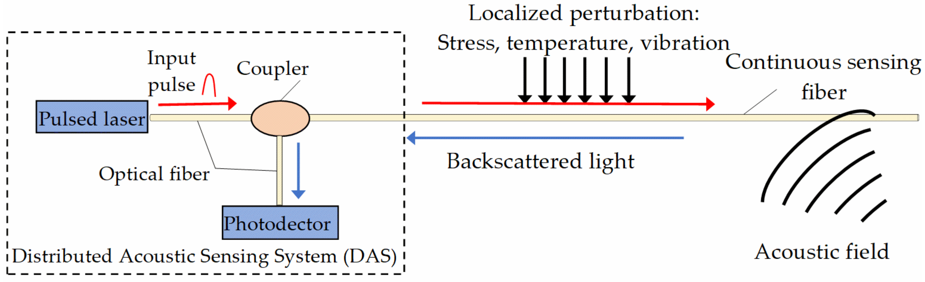
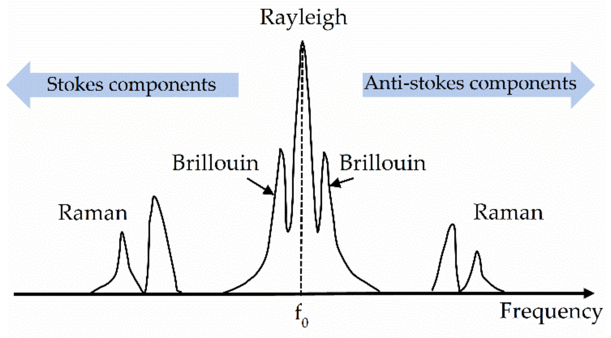
2.3. Scattering-Based Distributed Optical Fiber Sensors

Distributed OFS are promising optical sensing technologies for continuous and long measurement range up to several kilometers to monitor long distance structures such as pipeline, tunnel, long span cable bridges and so on [41,42]. Distributed OFS are based on the principles of Optical Time-Domain Reflectometry (OTDR) and Distributed Acoustic Sensing (DAS). The objective is to register the backscattering of optical pulses from an optical fiber sensor over its length. Figure 3 shows the fundamental principles of OTDR and DAS. The DAS consists of a laser source and a photodetector. Optical pulses are sent by the laser source to propagate into the optical fiber, serving as a sensor over its entire length. Photodetector detects the backscattering signals due to the return of some light photons to the DAS. Under stress, temperature and vibration changes in localized position of the fiber, the backscattering signals are modulated and varied in amplitude, frequency and phase. The variations in surrounding environment are detected by monitoring the backscattering signals either in amplitude, phase or frequency [43].
Currently, distributed OFS can be categorized into three groups based on the light scattering method: Brillouin, Rayleigh, and Raman scattering. Figure 4 shows each spectrum of the backscattered light properties in an optical fiber.
The interaction between the acoustic phonons and the incident light field induces an inelastic scattering, called the Brillouin scattering. The Brillouin frequency shift (BFS) is the frequency shift between the incident light and one of the stokes or anti-stokes light. The sensitivity of the Brillouin scattering to both strain and temperature leads to a linear relationship of the BFS versus strain and temperature change. The sensing range for a Brillouin-based scattering sensors can reach 100 to 150 km [44]. However, Brillouin scattering-based sensors suffer from limitations such as high spatial resolution (0.5–5 m) [45] and is unsuitable for short distance measurement. Since the 1990s, many kinds of Brillouin-based technologies have been developed to measure both strain and temperature, such as the Brillouin optical frequency domain analysis (BOFDA) [46] and reflectometer (BOFDR) [47], Brillouin optical time domain analysis (BOTDA) [48] and reflectometer (BOTDR) [49], Brillouin optical correlation domain analysis (BOCDA) [50] and reflectometer (BOCDR) [51], and Brillouin dynamic grating distributed sensing [52]. The Rayleigh scattering uses an elastic scattering that has been widely utilized by industries for health monitoring. There are several applications of Rayleigh scattering-based sensors, such as the OTDR and DAS techniques, the Optical Frequency Domain Reflectometry (OFDR), and the Optical Backscattered Reflectometry (OBR). OTDR and DAS based on Rayleigh scattering have a measurement range from 10–50 km, with low spatial resolution of 5–10 m that are suitable for dynamic measurements and long-distance monitoring. OFDR-based Rayleigh scattering has a low spatial resolution of 1 mm, but the measurement range is limited to 50–70 m, making such a system only suitable for short-distance distributed strain and temperature monitoring [53]. OBR is an enhanced backscattering distributed optical fiber sensor that consists of a special implementation of OFDR, polarization diversity and optical optimization [54]. OBR is a recent technique and is very quick for scanning a 30-m fiber with an unmatched spatial resolution of 1 mm or less and ultra-high resolution (10μm sampling) [55]. The Luna OBR-4600 has been used for measurement of distributed static strain while the ODiSi-6000 series has been used to measure the distributed dynamic rail strains [56]. The Raman scattering has identical scattering procedures with the Brillouin scattering (inelastic scattering), but can only measure the temperature parameter [57], with spatial resolution ranging from 1 cm to 17 m, and a sensing range up to 37 km [58].
Table 1 recapitulates the working principle of each distributed optical fiber sensing technique and their respective specifications, advantages and limitations.

3. Industrialized Optical Fiber Sensors for Monitoring Railway Parameters

This section reviews the application of industrialized OFS to monitor railway parameters. Various available industrialized optical fiber sensors in the market are first provided. Applications of industrialized OFS to monitor rails, rail components, concrete sleepers, rail subgrade, bridges and tunnels are then provided.

3.1. Industrialized OFS

The following points must be considered in the design of sensors suitable in practical engineering: robustness, easy installation, high-sensitivity, durability and reliability as well as no undesirable effect on the integrity of the monitored structures. According to sensor installation modes, OFS can be categorized into two categories: embedded sensors and surface-attached sensors, as shown in Figure 5. These two installation modes depend on the material properties, targeted parameters to be measured and loading conditions. For instance, surface-attached sensors are specifically used for steel-based structures, and embedded sensors are utilized for monitoring the internal temperature of concrete structures. Specific packaging measures can remedy the restrictions induced by the sensing and material properties of OFS, as well as increasing their robustness when embedded into structures.
Figure 6 shows some of the industrialized optical fiber sensors available to-date for SHM based on their packaging techniques. Based on the work of Wang et al. [25], the different paths of transferring the deformation of the host material to the sensing fiber define the classification of industrialized OFS. The first class (i.e., S-OF1 and E-OF1 in Figure 6) uses the interfacial shear force to transfer the deformation of the host material to the sensing fiber. For the second class (i.e., E-OF2 and S-OF2), the anchor pieces located at both ends of the sensing fiber transfers the deformation of the host material. For the third-class sensors (i.e., E-OF3), the deformation from the host material is transferred to the sensing fiber by both interfaces and two anchor pieces. Note that the distance between the anchors corresponds to the length of sensor L. The materials used for packaging the OFS include steel, fiber-reinforced polymer (FRP) and stainless-steel. Adhesive glues, such as Araldite, have been used to protect surface-bonded OFS from the harsh environment, but these packaging techniques are deemed to be used for short-term monitoring. Among the existing packaging methods from Figure 6, FRP-based packaging allows the sensing fiber with good durability and high-sensitivity characteristics due to the distinct benefits of FRP such as their elastic modulus, which is approximately equal to the optical fiber, good corrosive resistance, high strength, and so on. For steel packaged OFS, corrosion damage might occur during the lifespan of the sensors. Strain transfer analysis is the best method to improve the accuracy of the sensors, which will be discussed in Section 4.

3.2. Applications of Industrialized OFS in Railway Infrastructures
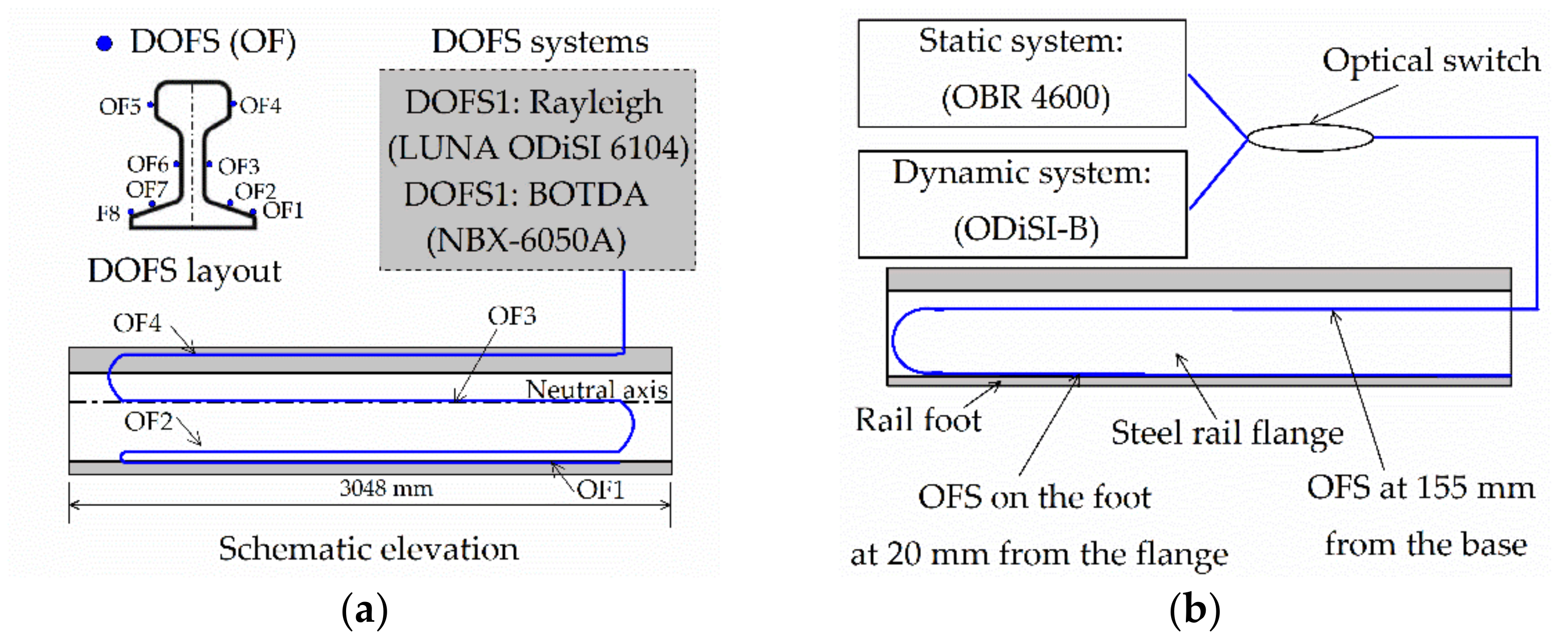
3.2.1. Rails

Many approaches using OFS have been proposed in the literature to monitor rail track conditions. Ping et al. [70] attached two FBGs on the rail web, as a bidirectional device (Figure 7a), to accurately measure the longitudinal force in a Chinese high-speed railway line. Sealing was used to protect the FBGs from potential hazards due to the external environment. Temperature compensation through calibration tests and 23 h tests were conducted. Zeni et al. [71] used a layout of distributed optical fiber sensors (DOFS) to monitor the railway traffic condition in real time on the Italian regional line, as shown in Figure 7b. A slope-assisted Brillouin optical time-domain analysis (SA-BOTDA) technique interrogated the signals from the DOFS. The sensors were bonded on the surface of the rail web with a fast-curing epoxy adhesive. The collected data are useful to measure the speed of train and monitor the dynamic loading states of the track.
Sun et al. [72] utilized two types of DOFS systems to detect the lateral buckling of a steel rail under axial loading. The DOFS is made of a nylon-coated single-mode optical fiber glued with an adhesive (Loctite 4861) at four different locations of each side of the rail (Figure 8a). The strain measurement from both Rayleigh- and Brillouin-based DOFS system demonstrated a high accuracy measurement from the first system, but is inappropriate for practical application due to short-distance limitation. Wheeler et al. [56] measured the dynamic strains of rail using a Rayleigh backscattered-based DOFS. The field test consists of a 7.5 m long section of rail and the sensing fibers are a nylon-coated single-mode fiber, installed on the rail at 20 mm and 155 mm from the bottom of the rail (Figure 8b). A static test was firstly performed up to 140 kN using the OBR 4600 analyzer from Luna Ltd. Then, the ODiSI-B analyzer captured the dynamic strains of the cyclic loading (14 kN to 140 kN using a frequency of 0.5 Hz). A recent study [73] used an hybrid system (FBG sensors and Raman based DOFS) to provide early warning defects on the rail track condition. The sensors were glued with a fast-curing adhesive, and was protected with waterproof protective patches.

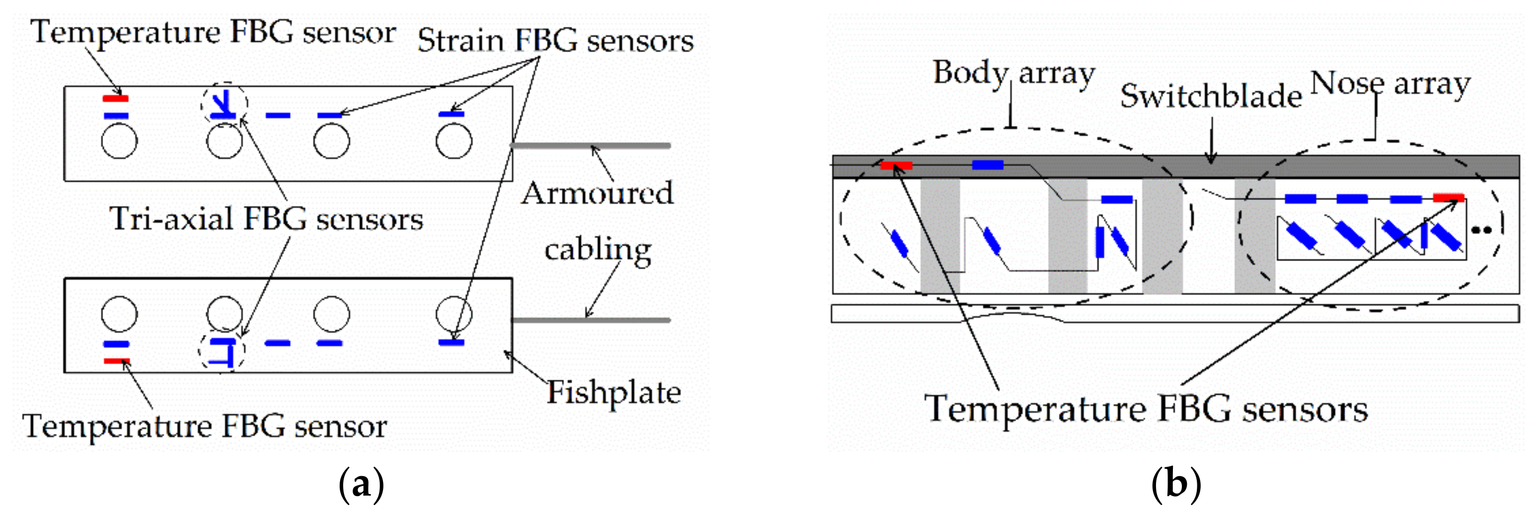
3.2.2. Rail Components

The only available literature for the safety condition of rail components using OFS is found in Buggy et al. [74] The sensor array installed on the rail fishplate (Figure 9a) consists of seven strain FBG sensors (blue) including a tri-axial FBG sensor, and a temperature FBG (red). For the switchblade, two arrays of FBG sensors (seven at the body array and nine at the nose array) were attached at each switchblade (Figure 9b). The tests were performed at the laboratory condition, and silicon sealant was used to protect the sensors. The sensors captured the dynamic strains from a movement of a tram at the sensor locations, and strains data are able to recognize some indicative features of state changes of the components. Thus, the FBG-based technique provides real-time monitoring of rail components.

3.2.3. Concrete Sleepers, Ballast and Ballastless Track Slab

Zhang et al. [75] proposed a long-term and real-time monitoring system for track slab on the Beijing-Shanghai high-speed railway using optical fiber accelerometer to record train-induced vibration. Under a long-term temperature load (in winter and summer), they found a positive correlation between the track slab deformation and the wavelet packet energy. Chapeleau et al. [76] proposed a DOFS to monitor the long-term condition of ballastless track in laboratory condition for high-speed railway line. Special optical fiber cables with good mechanical resistance were attached on steel rebars, then embedded into the concrete slab (see Figure 10a). The ballastless slab was tested under fatigue load for 10 million cycles. Rayleigh scattering technique (OFDR) is used to achieve a spatial resolution less than 2 cm. The distributed strain data allows to identify and localize cracks on the slab. A successfully deployment of the sensing system in a small section of onsite ballastless track has been achieved in France. Butler et al. [69] used robust optical fiber sensor arrays made of two FBG temperature sensors and several FBG strain sensors, to monitor the early-age performance of concrete sleepers. The sensors were attached on the prestressing wires during the production process at CEMEX facility in Birmingham, UK. Figure 10b shows the fabricated smart concrete sleepers with embedded robust FBG arrays. The sleepers are considered among innovative sleepers developed for modern railway transportation. Glass FRP and ceramic-based coatings are used to increase the robustness of the OFS, and a PTFE tubing is used for temperature-compensating FBG sensor. The data gathered from the embedded sensors provide relative measurement of performance during four months after production. The mechanical behavior of the smart sleepers has also been captured by the FBGs during a qualification test under three-point bending conditions.

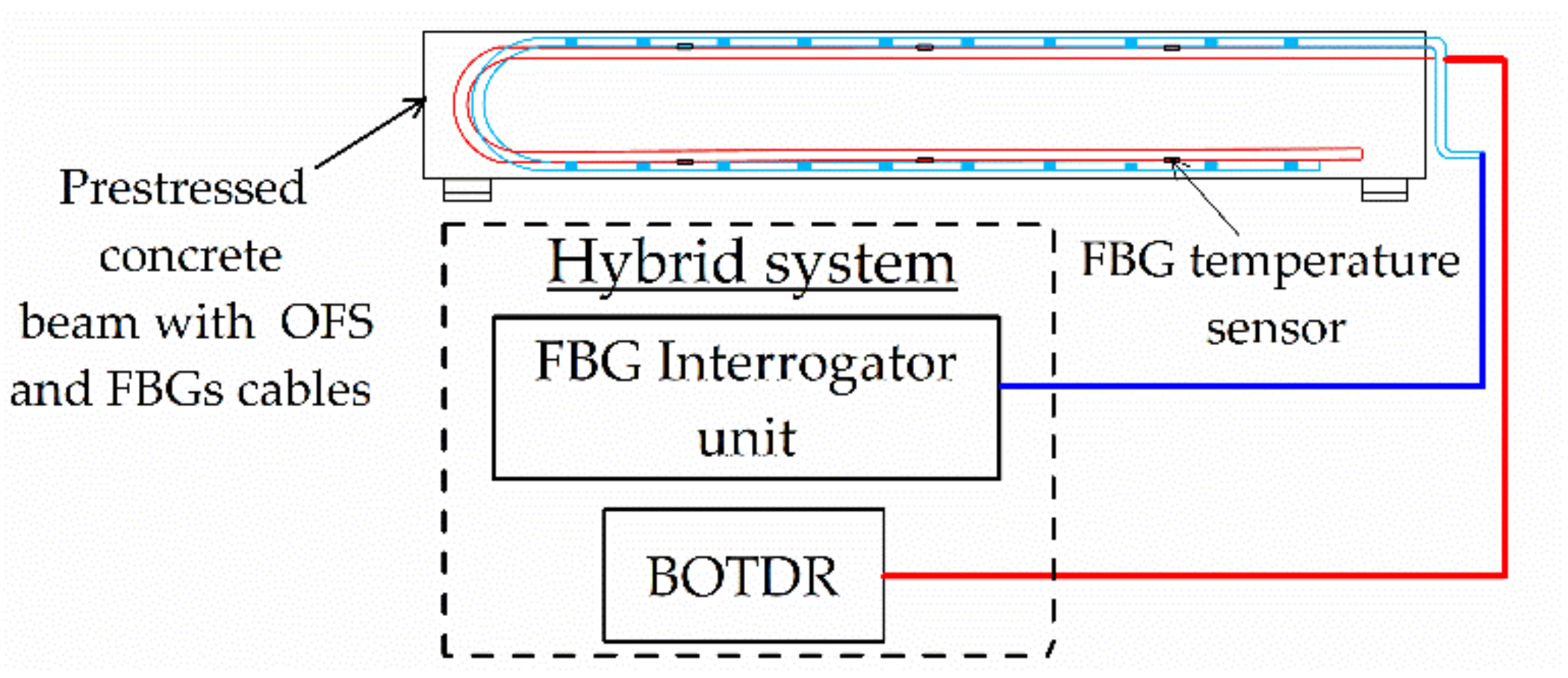
3.2.4. Railway Bridges and Tunnels

Kerrouche et al. [77] incorporated FBG sensors into carbon FRP (CFRP) for monitoring the strengthening condition of a 50 years aged railway bridge in Sweden. Before strengthening, a groove of 1 mm depth and 2 mm width was cut from the CFRP tube and rod, which serves to accommodate the seven FBG sensors glued with cyano-acrylate and covered with epoxy (Figure 11a). The monitoring results indicate that reliable strain measurements are possible to evaluate the strengthening condition of each strengthening component (rod and tube) in the elastic regime. Yoon et al. [78] demonstrated that the possibility of using the DOFS based on a BOCDA technique to monitor the real-time distributed strains of girder and rail in a railway bridge under train movement. The lower flange of the girder was equipped with Telecom optical fiber without treatment (Figure 11b), which was covered with a PET film of 0.3 mm thickness.
Ye et al. [79] used a hybrid system consisting of distributed and point OFS, to evaluate the prestressing force losses in the prestressed concrete girder of a newly constructed railway bridge in the U.K. Optical fiber cables including FBGs and distributed OFS (BOTDR) were mounted on the prestressing steel strands during manufacturing of the beams, according to the sensors layout shown in Figure 12. The same coating method from Butler et al. [69,80] was applied to the optical fiber-based sensors to ensure robustness, durability and long-term accuracy. Since concrete casting, temperature and strain were measured for two and half years. It was concluded that the hybrid system enables us to monitor the condition of the bridge structure from the beginning of its lifecycle. Velha et al. [73] used Raman distributed temperature sensing and FBG sensors to detect anomalies in masonry bridges along the railway network in Italy. Early warning of abnormal behavior has been detected with the setup sensing system. In their study, the sensors were glued to the structure and only a waterproof protective patch was used.
Ye et al. [81] monitored the construction safety of the railway tunnel with FBG sensing technology. An FBG-based temperature sensor assured the real-time measurement of temperature in the frozen soils, while in-situ FBG-based liquid-level sensors monitored the subgrade settlement. It was observed that the FBG sensors are strong enough to survive in harsh environments, but further enhancements are expected to improve the durability of the sensors.

3.2.5. Rail Foundation

Besides the monitoring of major parts in the railway system, optical fiber sensors were also adopted to monitor the stability of rail foundation and to characterize the landslides. OTDR and FBG sensing technologies were used in the retaining wall parallels to the Thompson River in Canada, to monitor multi-parameters such as displacement, local and distributed strain, and temperature [82]. The multi-parameter detection system prevents hazards from slow moving landslides to major onsite national rail lines. Minardo et al. [83] applied DOFS along the two walls of a railway tunnel located in Italy, to detect and identify potential dangerous strained regions due to an active landslide. The DOFS system used the Brillouin technique and showed successful results during a three-year span monitoring.

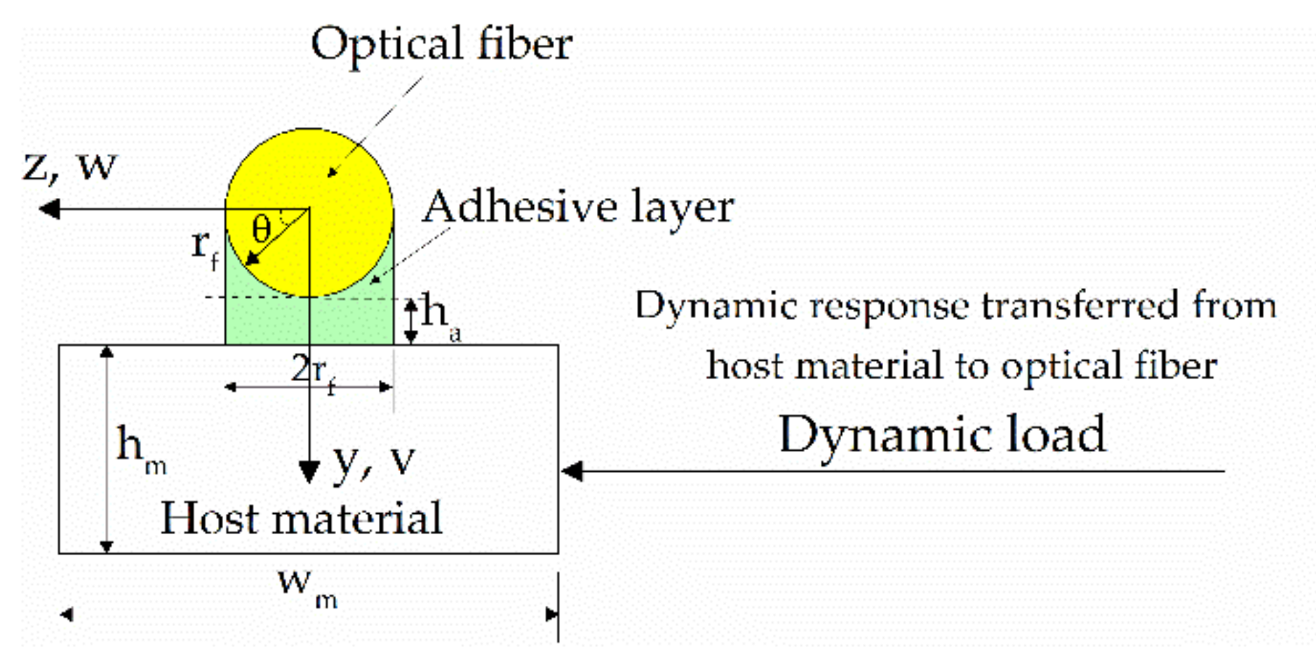
4. Parameter Reflection of Railway Structures Based on Strain Transfer Analysis

Based on the analysis in Section 3, it can be observed that different kinds of industrialized OFS have been developed to directly measure the strain, temperature, and vibration of railway systems. Therefore, how to use the measured information to characterize the parameters and identify the health state of railway structures has always been an important issue. Strain transfer analysis can thus be used to interpret the data measured by optical fiber sensors, and to reflect the structural parameters and health state of railways [25,84,85,86].
Considerable research has contributed to the investigation on the strain transfer mechanism of multi-layered sensing models under different loading conditions. Wang et al. [87] investigated the strain transfer relationship between the sensing fiber and the monitored structures under fatigue load, and the performance of FBG sensors to reflect the dynamic response of structures was also explored [88,89]. Wang and Dai explored the strain transfer relationship when a three surface-attached sensing model is subjected to a thermal load [90]. The cases of monitored structure with local damage (i.e., crack and interfacial debonding) have been also discussed [84,85,91]; they are used to instruct the durability and robustness design of optical fiber-based sensors in civil engineering. Based on the analysis, the suggestions to improve temperature compensation are given when the structures are subjected to mechanical load, thermal load or the combined actions [92]. These studies can be implemented to instruct the establishment of an optical fiber sensing system for the structural health monitoring of railway infrastructures with a high accuracy, a low cost and long-term stability.
Based on the effective data collected by the sensors, mechanical analysis is required to understand the interactive effect between the railways and the sensors, and then the railway structural parameters can be characterized. For train bodies, the deformation is mainly caused by the surrounding pressure and temperature variations. Axles and wheels are the key components of the bogies, and their rotation can produce mechanical friction with the contact components. The deformation and pressure of the track wheel can be measured by the surrounded FBGs in series, as is shown in Figure 13a. By establishing the mechanical model with the symmetry considered, as shown in Figure 14, the dynamic response of the wheel can be characterized. The continuous monitoring data can be further used to determine the health status and to identify the possible damage (micro-crack, wheel flat) of the wheels based on the parametric inverse analysis. For the rail track, the distributed optical fiber sensors are attached to check the longitudinal deformation and shape profile, as shown in Figure 13b. Local FBG sensors attached in the vertical direction can be adopted to measure the pressure and to identify the load transferred from the train to the track. The combined data from the distributed optical fiber and point FBG sensors can be further used to check the track settlement. It should be noted that the parametric reflection methods are based on mechanical and mathematical theory. Except for the two general methods, the signal processing method (i.e., frequency domain technique and time domain technique) can be also an efficient way to identify partial feature parameters of the railway system [93]. The proper selection of a feasible method for parameter reflection correlates with the loading conditions, the boundary constraints and the working status of the monitored components.

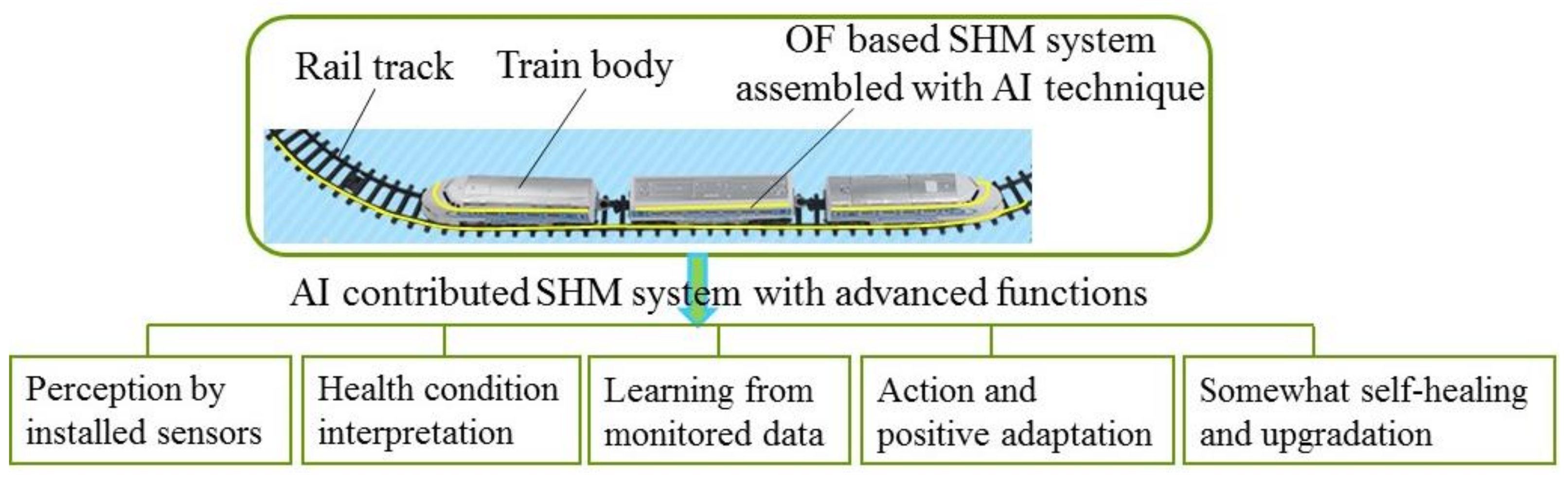
5. Smart Concept for AI Contribution in Monitoring System of Railway Infrastructures

AI technology is a comprehensive subject with machine learning and computer vision included, which can be used to make the railway structures with smart consciousness by introducing the sensing system. Optical fiber sensors can be considered as neural networks of the railways, and actuate the train bodies, wheels and tracks positively responded to the sudden intrusion, extreme weather (i.e., rainstorm, heavy snowfall, and freeze), impact and earthquake actions [94]. The features of the smart concept can be the self-healing of structural defects by a combined use of the smart sensors and materials. This means that the railway structure is expected to behave like a human and can have a somewhat self-consciousness and adjustment to the external action by using statistics, informatics and cybernetics.
Currently, the use of AI in civil engineering has attracted considerable attention. Partial study explores the use of AI in construction industry [95,96], and some studies predict the use of AI in SHM field [97]. As one important subfield of AI, machine learning means that the computers can learn from collected data and make predictions on the data evolution, which exhibits intelligence like a human. By using algorithms, machine learning and computer vision, the AI contributed SHM system can accumulate experiences through both engineering and modeling approaches, and then solve certain general problems by itself, as shown in Figure 15. It is expected that the AI technique can enhance the function of the SHM system from damage identification, model updating, and condition assessment to self-adaptation, self-healing and self-upgradation. With the rapid development of smart sensors and smart functional materials, AI that contributes to the SHM system can be a promising tool to deal with the health monitoring, condition assessment, structural safety, self-healing with microdamage, self-protection and upgradation with sudden intrusion or strong action.
Besides, the building information modeling (BIM) and digital twin technology can also be assembled in the SHM system, which can be an additional part to assist in the smart management of structural performance rehabilitation and maintenance [98,99,100]. In other words, the SHM system assembled with BIM and a digital twin can produce advance functions. With the efficient use of monitored data information of the railway structures, the operation management and the safety control can become intelligent, which is expected in engineering.

6. Conclusions

The study gives a general literature review on the application of an OFS-based SHM system of railway infrastructures and its possible combination with an AI technique. Through the analysis, the following conclusions can be drawn: |
(1)
A concise report on the applications/studies of novel optical fiber based sensors in civil engineering and the possible use in the railway system is given.
(2)
Review of the application of industrialized OFS in the monitoring of structural parameters and damage status is provided, which declares the intensive use of OFS in the railway system.
(3)
Strain transfer-based parameter reflection of railway structures is discussed, which further declares the innovative ways for feature identification and health state prediction.
(4)
Smart concept for the AI contribution in the SHM system of railway structures is conferred and the possible advanced functions (i.e., adaptation and upgradation) are declared, which can provide challenging instructions for the development of SHM systems and the extended function (i.e., BIM and digital twin) for the smart management in the railway industry.
(5)
Applications of OFS embedded into fiber-reinforced composite materials to design self-sensing structural components to monitor the parameters of railway infrastructures, which can be further conducted by association with the strain transfer analysis and AI-based technology.

Author Contributions

Conceptualization, formal analysis, resources, data curation, writing—original draft preparation, Y.W.S.C.; writing (Section 4, Section 5 and Section 6), review and editing, H.-P.W.; investigation and supervision, P.X. All authors have read and agreed to the published version of the manuscript.

Funding

This research was funded by the National Natural Science Foundation of China (Grant No. 51908263), Double First-Class (First-Class University and First-Class Disciplines) Funds of Lanzhou University (Grant No. 561119201), the Fundamental Research Funds for the Central Universities (Grant No. lzujbky-2020-56), Key Laboratory of Structures Dynamic Behavior and Control (Ministry of Education) in Harbin Institute of Technology (Grant No. HITCE201901), Gansu Provincial Projects (2020-0624-RCC-0013 and JK2021-18), the National Natural Science Foundation of China (11972379), the R&D Program of Hunan Province (2020SK2060), Hunan Science Fund for Distinguished Young Scholars (2021JJ10061).

Institutional Review Board Statement

Not applicable.

Informed Consent Statement

Not applicable.

Data Availability Statement

The data supporting the results reported in the paper can be accessed from the corresponding authors.

Acknowledgments

Special thanks are due to Jinping Ou and Zhi Zhou of Dalian University of Technology, and Youhe Zhou and Ning Huang of Lanzhou University. The findings and opinions expressed in this article are only those of the authors and do not necessarily reflect the views of the sponsors.

Conflicts of Interest

The authors declare no conflict of interest.

References

  1. Gou, H.; Leng, D.; Bao, Y.; Pu, Q. Cumulative deformation of high-speed railway bridge pier under repeated earthquakes. Earthq. Struct. 2019, 16, 391–399. [Google Scholar] [CrossRef]
  2. Wang, Q.; Liu, K.; Wang, M.; Koks, E.E. A River Flood and Earthquake Risk Assessment of Railway Assets along the Belt and Road. Int. J. Disaster Risk Sci. 2021, 12, 553–567. [Google Scholar] [CrossRef]
  3. Kyriakidis, M.; Pak, K.T.; Majumdar, A. Railway Accidents Caused by Human Error: Historic Analysis of UK Railways, 1945 to 2012. Transp. Res. Rec. 2015, 2476, 126–136. [Google Scholar] [CrossRef]
  4. Meng, Z.; Shu, C.; Wu, Q.; Wang, Y.; Yang, Y.; Fu, Z. Surface Deformation of High-Speed Railway Between Changchun and Harbin Based on Time-Series Insar Techinque. In Proceedings of the IGARSS 2020—2020 IEEE International Geoscience and Remote Sensing Symposium, Waikoloa, HI, USA, 26 September–2 October 2020; pp. 1023–1026. [Google Scholar]
  5. Bian, X.; Jiang, H.; Chen, Y. Accumulative deformation in railway track induced by high-speed traffic loading of the trains. Earthq. Eng. Eng. Vib. 2010, 9, 319–326. [Google Scholar] [CrossRef]
  6. Lai, Z.; Kang, X.; Jiang, L.; Zhou, W.; Fetng, Y.; Zhang, Y.; Yu, J.; Nie, L. Earthquake Influence on the Rail Irregularity on High-Speed Railway Bridge. Shock Vib. 2020, 2020, 4315304. [Google Scholar] [CrossRef]
  7. Lin, W.; Taniguchi, N.; Yoda, T.; Satake, S. A Preventive Strengthening Strategy for Aged Steel Columns; CRC Press—Taylor & Francis Group: Boca Raton, FL, USA, 2018. [Google Scholar]
  8. Wang, Q.A.; Ni, Y.Q. Measurement and Forecasting of High-Speed Rail Track Slab Deformation under Uncertain SHM Data Using Variational Heteroscedastic Gaussian Process. Sensors 2019, 19, 3311. [Google Scholar] [CrossRef] [PubMed] [Green Version]
  9. Chang, F.K. Ultra reliable and super safe structures for the new century. In Proceedings of the First European Workshop on Structural Health Monitoring, Paris, France, 10–12 July 2002. [Google Scholar]
  10. Barke, D.; Chiu, W.K. Structural Health Monitoring in the Railway Industry: A Review. Struct. Health Monit. 2005, 4, 81–93. [Google Scholar] [CrossRef]
  11. Balliet, H.S. The Invention of the Track Circuit: The History of Dr. William Robinson’s Invention of the Track Circuit, the Fundamental Unit Which Made Possible Our Present Automatic Block Signaling and Interlocking Systems; Signal Section, American Railway Association: Washington, DC, USA, 1922. [Google Scholar]
  12. Soni, A.; Robson, S.; Gleeson, B. Structural monitoring for the rail industry using conventional survey, laser scanning and photogrammetry. Appl. Geomat. 2015, 7, 123–138. [Google Scholar] [CrossRef]
  13. Macchi, M.; Garetti, M.; Centrone, D.; Fumagalli, L.; Piero Pavirani, G. Maintenance management of railway infrastructures based on reliability analysis. Reliab. Eng. Syst. Saf. 2012, 104, 71–83. [Google Scholar] [CrossRef]
  14. Mori, H.; Tsunashima, H.; Kojima, T.; Matsumoto, A.; Mizuma, T. Condition Monitoring of Railway Track Using In-service Vehicle. J. Mech. Syst. Transp. Logist. 2010, 3, 154–165. [Google Scholar] [CrossRef] [Green Version]
  15. Chraim, F.; Puttagunta, S. Monitoring Track Health Using Rail Vibration Sensors; Academia. Available online: https://www.academia.edu/7833123/Monitoring_Track_Health_Using_Rail_Vibration_Sensors. (accessed on 10 September 2021).
  16. Thakkar, N.A.; Steel, J.A.; Reuben, R.L. Rail–wheel interaction monitoring using Acoustic Emission: A laboratory study of normal rolling signals with natural rail defects. Mech. Syst. Signal Process. 2010, 24, 256–266. [Google Scholar] [CrossRef]
  17. Clark, A.; Kaewunruen, S.; Janeliukstis, R.; Papaelias, M. Damage Detection in Railway Prestressed Concrete Sleepers using Acoustic Emission. IOP Conf. Ser. Mater. Sci. Eng. 2017, 251, 012068. [Google Scholar] [CrossRef] [Green Version]
  18. Zhang, X.; Feng, N.; Wang, Y.; Shen, Y. Acoustic emission detection of rail defect based on wavelet transform and Shannon entropy. J. Sound Vib. 2015, 339, 419–432. [Google Scholar] [CrossRef]
  19. Edwards, J.R.; Gao, Z.; Wolf, H.E.; Dersch, M.S.; Qian, Y. Quantification of concrete railway sleeper bending moments using surface strain gauges. Measurement 2017, 111, 197–207. [Google Scholar] [CrossRef]
  20. Pisanu, T.; Buffa, F.; Poppi, S.; Marongiu, P.; Serra, G.; Vargiu, G.P.; Concu, R. The SRT inclinometer for monitoring the rail and the thermal gradient effects on the alidade structure. In Ground-Based and Airborne Telescopes V, Proceedings of the SPIE Astronomical Telescopes + Instrumentation, Montréal, QC, Canada, 22–27 June 2014; SPIE: Bellingham, WA, USA, 2014; p. 91454R. [Google Scholar]
  21. Carboni, M.; Collina, A.; Liu, R.; Zappa, E. A preliminary feasibility analysis about the structural health monitoring of railway concrete sleepers by acoustic emission and digital image correlation. In Proceedings of the International Symposium on Structural Health Monitoring and Nondestructive Testing (SHM-NDT 2018), Saarbruecken, Germany, 4–5 October 2018; pp. 1–9. [Google Scholar]
  22. Zhou, Z.; Sasy Chan, Y.W.; Ou, J.P. Optical fiber sensor-based smart structures. J. Phys. Conf. Ser. 2018, 1065, 252003. [Google Scholar] [CrossRef] [Green Version]
  23. Sasy Chan, Y.W.; Zhou, Z.; Liu, W.; Ou, J. OFBG-Based Smart Double-Skin Tubular Confined-Concrete Column with Basalt FRP-Steel Composite. Sensors 2019, 19, 3572. [Google Scholar] [CrossRef] [Green Version]
  24. Zhou, Z.; Sasy Chan, Y.W.; Ou, J.P. Advances in FRP-Based Smart Components and Structures. In Structural Health Monitoring of Composite Structures Using Fiber Optic Methods, 1st ed.; Rajan, G., Prusty, B.G., Eds.; CRC Press: Boca Raton, FL, USA, 2016; pp. 371–413. [Google Scholar]
  25. Wang, H.P.; Xiang, P.; Jiang, L.Z. Strain transfer theory of industrialized optical fiber-based sensors in civil engineering: A review on measurement accuracy, design and calibration. Sens. Actuator A Phys. 2019, 285, 414–426. [Google Scholar] [CrossRef]
  26. Udd, E. Overview of Fiber Optic Sensors. In Fiber Optic Sensors, 2nd ed.; Yin, S., Ruffin, P.B., Yu, F.T.S., Eds.; CRC Press: Boca Raton, FL, USA, 2008; pp. 1–34. [Google Scholar]
  27. Zhang, L.; Zhang, W.; Bennion, I. In-Fiber Grating Optic Sensors. In Fiber Optic Sensors, 2nd ed.; CRC Press: Boca Raton, FL, USA, 2008; pp. 109–162. [Google Scholar]
  28. Tosi, D. Review and Analysis of Peak Tracking Techniques for Fiber Bragg Grating Sensors. Sensors 2017, 17, 2368. [Google Scholar] [CrossRef]
  29. Lee, B.; Jeong, Y. Interrogation Techniques for Fiber Grating Sensors and the Theory of Fiber Gratings. In Fiber Optic Sensors, 2nd ed.; Yin, S., Ruffin, P.B., Yu, F.T.S., Eds.; CRC Press: Boca Raton, FL, USA, 2008; pp. 253–332. [Google Scholar]
  30. F610A-FBG Wavelength Interrogator. Available online: https://www.fiberer.com/FBG-wavelength-interrogator.html (accessed on 27 September 2021).
  31. Li, R.; Tan, Y.; Chen, Y.; Hong, L.; Zhou, Z. Investigation of sensitivity enhancing and temperature compensation for fiber Bragg grating (FBG)-based strain sensor. Opt. Fiber Technol. 2019, 48, 199–206. [Google Scholar] [CrossRef]
  32. Azhari, A.; Liang, R.; Toyserkani, E. A novel fibre Bragg grating sensor packaging design for ultra-high temperature sensing in harsh environments. Meas. Sci. Technol. 2014, 25, 11. [Google Scholar] [CrossRef]
  33. Li, D.; Zhou, Z.; Ou, J. Development and sensing properties study of FRP-FBG smart stay cable for bridge health monitoring applications. Measurement 2011, 44, 722–729. [Google Scholar] [CrossRef]
  34. Dandridge, A. Fiber Optic Sensors Based on the Mach–Zehnder and Michelson Interferometers. In Fiber Optic Sensors: An Introduction for Engineers and Scientists, 2nd ed.; Udd, E., Spillman, W.B., Jr., Eds.; John Wiley & Sons: Hoboken, NJ, USA, 2011; pp. 231–275. [Google Scholar]
  35. Liu, Y.; Lin, H.; Dai, Y.; Zhou, A.; Yuan, L. Fiber In-Line Mach–Zehnder Interferometer for Gas Pressure Sensing. IEEE Sens. J. 2018, 18, 8012–8016. [Google Scholar] [CrossRef]
  36. Wu, Y.; Xu, Y.; Yang, Y.; Jin, W.; Jiang, Y.; Shen, Y.; Jian, S. High-sensitivity pressure sensor based on fiber Mach–Zehnder interferometer. Meas. Sci. Technol. 2017, 28, 105102. [Google Scholar] [CrossRef] [Green Version]
  37. Taylor, H. Fiber Optic Sensors Based upon the Fabry–Perot Interferometer. In Fiber Optic Sensors, 2nd ed.; CRC Press: Boca Raton, FL, USA, 2008; pp. 35–64. [Google Scholar]
  38. Zhang, G.; Yu, Q.; Song, S. An investigation of interference/intensity demodulated fiber-optic Fabry–Perot cavity sensor. Sens. Actuator A Phys. 2004, 116, 33–38. [Google Scholar] [CrossRef]
  39. Xiao, G.; Adnet, A.; Zhang, Z.; Lu, Z.; Grover, C. Fiber Optic Fabry-Perot Interferometric Gas Pressure Sensors Embedded in Pressure Fittings. Microw. Opt. Technol. Lett. 2004, 42, 486–489. [Google Scholar] [CrossRef]
  40. Islam, M.R.; Ali, M.M.; Lai, M.-H.; Lim, K.-S.; Ahmad, H. Chronology of Fabry-Perot Interferometer Fiber-Optic Sensors and Their Applications: A Review. Sensors 2014, 14, 7451–7488. [Google Scholar] [CrossRef] [PubMed] [Green Version]
  41. Feng, X.; Wu, W.; Meng, D.; Ansari, F.; Zhou, J. Distributed monitoring method for upheaval buckling in subsea pipelines with Brillouin optical time-domain analysis sensors. Adv. Struct. Eng. 2016, 20, 180–190. [Google Scholar] [CrossRef]
  42. Bado, M.F.; Casas, J.R. A Review of Recent Distributed Optical Fiber Sensors Applications for Civil Engineering Structural Health Monitoring. Sensors 2021, 21, 1818. [Google Scholar] [CrossRef]
  43. He, Z.; Liu, Q.; Fan, X.; Chen, D.; Wang, S.; Yang, G. A Review on Advances in Fiber-optic Distributed Acoustic Sensors (DAS). In Proceedings of the CLEO Pacific Rim Conference, Conference on Lasers and Electro-Optics/Pacific Rim, Hong Kong, China, 29 July–3 August 2018; Optica Publishing Group: Washington, DC, USA, 2018; p. Th2L.1. [Google Scholar]
  44. Bao, X.; Chen, L. Recent Progress in Distributed Fiber Optic Sensors. Sensors 2012, 12, 8601–8639. [Google Scholar] [CrossRef] [PubMed] [Green Version]
  45. Dong, Y.; Chen, L.; Bao, X. Extending the Sensing Range of Brillouin Optical Time-Domain Analysis Combining Frequency-Division Multiplexing and In-Line EDFAs. J. Light. Technol. 2012, 30, 1161–1167. [Google Scholar] [CrossRef]
  46. Garcus, D.; Gogolla, T.; Krebber, K.; Schliep, F. Brillouin optical-fiber frequency-domain analysis for distributed temperature and strain measurements. J. Light. Technol. 1997, 15, 654–662. [Google Scholar] [CrossRef]
  47. Minardo, A.; Bernini, R.; Ruiz-Lombera, R.; Mirapeix, J.; Lopez-Higuera, J.M.; Zeni, L. Proposal Proposal of Brillouin optical frequency-domain reflectometry (BOFDR). Opt. Express 2016, 24, 29994–30001. [Google Scholar] [CrossRef] [PubMed]
  48. Kurashima, T.; Horiguchi, T.; Tateda, M. Distributed-temperature sensing using stimulated Brillouin scattering in optical silica fibers. Opt. Lett. 1990, 15, 1038–1040. [Google Scholar] [CrossRef] [PubMed]
  49. Kurashima, T.; Horiguchi, T.; Izumita, H.; Furukawa, S.; Koyamada, Y. Brillouin optical-fiber time domain reflectometry. Int. Quantum Electron. Conf. 1993, E76-B, 382–390. [Google Scholar]
  50. Jeong, J.H.; Lee, K.; Song, K.Y.; Jeong, J.-M.; Lee, S.B. Differential measurement scheme for Brillouin Optical Correlation Domain Analysis. Opt. Express 2012, 20, 27094–27101. [Google Scholar] [CrossRef]
  51. Mizuno, Y.; Zou, W.; He, Z.; Hotate, K. Proposal of Brillouin optical correlation-domain reflectometry (BOCDR). Opt. Express 2008, 16, 12148–12153. [Google Scholar] [CrossRef]
  52. Bao, X.; Chen, L. Recent Progress in Brillouin Scattering Based Fiber Sensors. Sensors 2011, 11, 4152–4187. [Google Scholar] [CrossRef]
  53. Kreger, S.; Rahim, N.A.A.; Garg, N.; Klute, S.M.; Metrey, D.R.; Beaty, N.; Jeans, J.W.; Gamber, R. Optical frequency domain reflectometry: Principles and applications in fiber optic sensing. In SPIE Fiber Optic Sensors and Applications XIII, Proceedings of the SPIE Comercial + Scientific Sensing and Imaging, Baltimore, MD, USA, 17–21 April 2016; SPIE: Bellingham, WA, USA, 2016; p. 98520T. [Google Scholar]
  54. Tosi, D.; Molardi, C.; Sypabekova, M.; Blanc, W. Enhanced Backscattering Optical Fiber Distributed Sensors: Tutorial and Review. IEEE Sens. J. 2021, 21, 12667–12678. [Google Scholar] [CrossRef]
  55. OBR 4600. Available online: https://lunainc.com/product/obr-4600 (accessed on 10 September 2021).
  56. Wheeler, L.N.; Pannese, E.; Hoult, N.A.; Take, W.A.; Le, H. Measurement of distributed dynamic rail strains using a Rayleigh backscatter based fiber optic sensor: Lab and field evaluation. Transp. Geotech. 2018, 14, 70–80. [Google Scholar] [CrossRef]
  57. Failleau, G.; Beaumont, O.; Razouk, R.; Delepine-Lesoille, S.; Landolt, M.; Courthial, B.; Hénault, J.; Martinot, F.; Bertrand, J.; Hay, B. A metrological comparison of Raman-distributed temperature sensors. Measurement 2018, 116, 18–24. [Google Scholar] [CrossRef]
  58. Soto, M.A.; Sahu, P.; Faralli, S.; Bolognini, G.; Di Pasquale, F.; Nebendahl, B.; Rueck, C. Distributed temperature sensor system based on Raman scattering using correlation-codes. Electron. Lett. 2007, 43, 862–864. [Google Scholar] [CrossRef] [Green Version]
  59. Du, C.; Dutta, S.; Kurup, P.; Yu, T.; Wang, X. A review of railway infrastructure monitoring using fiber optic sensors. Sens. Actuator A Phys. 2020, 303, 111728. [Google Scholar] [CrossRef]
  60. Speziale, S.; Marquardt, H.; Duffy, T.S. Brillouin Scattering and its Application in Geosciences. Rev. Mineral. Geochem. 2014, 78, 543–603. [Google Scholar] [CrossRef]
  61. Galindez-Jamioy, C.A.; López-Higuera, J.M. Brillouin Distributed Fiber Sensors: An Overview and Applications. J. Sens. 2012, 2012, 204121. [Google Scholar] [CrossRef] [Green Version]
  62. Zou, W.; Long, X.; Chen, J. Brillouin Scattering in Optical Fibers and Its Application to Distributed Sensors. In Advances in Optical Fiber Technology: Fundamental Optical Phenomena and Applications; IntechOpen: London, UK, 2015. [Google Scholar]
  63. Yuksel, K.; Wuilpart, M.; Moeyaert, V.; Megret, P. Optical frequency domain reflectometry: A review. In Proceedings of the 2009 11th International Conference on Transparent Optical Networks, Ponta Delgada, Portugal, 28 June–2 July 2009; pp. 1–5. [Google Scholar]
  64. ODiSI 6000 Series. Available online: https://lunainc.com/product/odisi-6000-series (accessed on 10 September 2021).
  65. Ghildiyal, S.; Ranjan, P.; Mishra, S.; Balasubramaniam, R.; John, J. Fabry–Perot Interferometer-Based Absolute Pressure Sensor With Stainless Steel Diaphragm. IEEE Sens. J. 2019, 19, 6093–6101. [Google Scholar] [CrossRef]
  66. Chen, Z.; Xiong, S.; Gao, S.; Zhang, H.; Wan, L.; Huang, X.; Huang, B.; Feng, Y.; Liu, W.; Li, Z. High-Temperature Sensor Based on Fabry-Perot Interferometer in Microfiber Tip. Sensors 2018, 18, 202. [Google Scholar] [CrossRef] [PubMed] [Green Version]
  67. Berardi, M.; Bielawski, K.; Rijnveld, N.; Gruca, G.; Aardema, H.; van Tol, L.; Wuite, G.; Akca, B.I. Optical interferometry based micropipette aspiration provides real-time sub-nanometer spatial resolution. Commun. Biol. 2021, 4, 610. [Google Scholar] [CrossRef]
  68. Zhu, Z.; Ba, D.; Liu, L.; Qiu, L.; Yang, S.; Dong, Y. Multiplexing of Fabry-Pérot Sensor by Frequency Modulated Continuous Wave Interferometry for Quais-Distributed Sensing Application. J. Light. Technol. 2021, 39, 4529–4534. [Google Scholar] [CrossRef]
  69. Butler, L.J.; Xu, J.; He, P.; Gibbons, N.; Dirar, S.; Middleton, C.R.; Elshafie, M.Z. Robust fibre optic sensor arrays for monitoring early-age performance of mass-produced concrete sleepers. Struct. Health Monit. 2017, 17, 635–653. [Google Scholar] [CrossRef]
  70. Wang, P.; Xie, K.; Shao, L.; Yan, L.; Xu, J.; Chen, R. Longitudinal force measurement in continuous welded rail with bi-directional FBG strain sensors. Smart Mater. Struct. 2015, 25, 015019. [Google Scholar] [CrossRef]
  71. Zeni, L.; Minardo, A.; Porcaro, G.; Giannetta, D.; Bernini, R. Monitoring railways with optical fibers. SPIE Newsroom 2013. Available online: https://www.spie.org/news/5246-monitoring-railways-with-optical-fibers?SSO=1 (accessed on 10 September 2021). [CrossRef]
  72. Sun, F.; Hoult, N.A.; Butler, L.J.; Zhang, M. Distributed monitoring of rail lateral buckling under axial loading. J. Civ. Struct. Health Monit. 2021. [Google Scholar] [CrossRef]
  73. Velha, P.; Nannipieri, T.; Signorini, A.; Morosi, M.; Solazzi, M.; Barone, F.; Frisoli, A.; Ricciardi, L.; Eusepi, R.; Icardi, M.; et al. Monitoring Large Railways Infrastructures Using Hybrid Optical Fibers Sensor Systems. IEEE Trans. Intell. Transp. Syst. 2020, 21, 5177–5188. [Google Scholar] [CrossRef]
  74. Buggy, S.J.; James, S.W.; Staines, S.; Carroll, R.; Kitson, P.; Farrington, D.; Drewett, L.; Jaiswal, J.; Tatam, R. Railway track component condition monitoring using optical fibre Bragg grating sensors. Meas. Sci. Technol. 2016, 27, 055201. [Google Scholar] [CrossRef] [Green Version]
  75. Zhang, J.; Huang, W.; Zhang, W.; Li, F.; Du, Y. Train-Induced Vibration Monitoring of Track Slab under Long-Term Temperature Load Using Fiber-Optic Accelerometers. Sensors 2021, 21, 787. [Google Scholar] [CrossRef] [PubMed]
  76. Chapeleau, X.; Sedran, T.; Cottineau, L.-M.; Cailliau, J.; Taillade, F.; Gueguen, I.; Henault, J.-M. Study of ballastless track structure monitoring by distributed optical fiber sensors on a real-scale mockup in laboratory. Eng. Struct. 2013, 56, 1751–1757. [Google Scholar] [CrossRef]
  77. Kerrouche, A.; Boyle, W.; Gebremichael, Y.; Sun, T.; Grattan, K.; Täljsten, B.; Bennitz, A. Field tests of fibre Bragg grating sensors incorporated into CFRP for railway bridge strengthening condition monitoring. Sens. Actuator A Phys. 2008, 148, 68–74. [Google Scholar] [CrossRef]
  78. Yoon, H.-J.; Song, K.-Y.; Choi, C.; Na, H.-S.; Kim, J.-S. Real-Time Distributed Strain Monitoring of a Railway Bridge during Train Passage by Using a Distributed Optical Fiber Sensor Based on Brillouin Optical Correlation Domain Analysis. J. Sens. 2016, 2016, 1–10. [Google Scholar] [CrossRef] [Green Version]
  79. Ye, C.; Butler, L.J.; Elshafie, M.Z.E.B.; Middleton, C.R. Evaluating prestress losses in a prestressed concrete girder railway bridge using distributed and discrete fibre optic sensors. Constr. Build. Mater. 2020, 247, 118518. [Google Scholar] [CrossRef]
  80. Butler, L.J.; Gibbons, N.; He, P.; Middleton, C.; Elshafie, M.Z.E.B. Evaluating the early-age behaviour of full-scale prestressed concrete beams using distributed and discrete fibre optic sensors. Constr. Build. Mater. 2016, 126, 894–912. [Google Scholar] [CrossRef]
  81. Ye, X.W.; Ni, Y.Q.; Yin, J.H. Safety Monitoring of Railway Tunnel Construction Using FBG Sensing Technology. Adv. Struct. Eng. 2013, 16, 1401–1409. [Google Scholar] [CrossRef]
  82. Bobrowsky, P.; Sladen, W.; Huntley, D.; Quing, Z.; Bunce, C.; Edwards, T.; Hendry, M.; Martin, D.; Choi, E. Multi-parameter Monitoring of a Slow Moving Landslide: Ripley Slide, British Columbia, Canada. In Engineering Geology for Society and Territory; Lollino, G., Giordan, D., Crosta, G.B., Corominas, J., Azzam, R., Wasowski, J., Sciarra, N., Eds.; Springer International Publishing: Cham, Switzerland, 2015; Volume 2, pp. 155–158. [Google Scholar]
  83. Minardo, A.; Catalano, E.; Coscetta, A.; Zeni, G.; Di Maio, C.; Vassallo, R.; Picarelli, L.; Coviello, R.; Macchia, G.; Zeni, L. Long-Term Monitoring of a Tunnel in a Landslide Prone Area by Distributed Optical Fiber Sensors. In Proceedings of the GARSS 2020—2020 IEEE International Geoscience and Remote Sensing Symposium, Waikoloa, HI, USA, 26 September–2 October 2020; pp. 6600–6603. [Google Scholar]
  84. Wang, H.P.; Xiang, P. Strain transfer analysis of optical fiber based sensors embedded in an asphalt pavement structure. Meas. Sci. Technol. 2016, 27, 075106. [Google Scholar] [CrossRef]
  85. Wang, H.P.; Jiang, L.Z.; Xiang, P. Improving the durability of the optical fiber sensor based on strain transfer analysis. Opt. Fiber Technol. 2018, 42, 97–104. [Google Scholar] [CrossRef]
  86. Wang, H.P.; Jiang, L.Z.; Xiang, P. Priority design parameters of industrialized optical fiber sensors in civil engineering. Opt. Laser Technol. 2018, 100, 119–128. [Google Scholar] [CrossRef]
  87. Wang, H.P.; Xiang, P.; Li, X. Theoretical Analysis on Strain Transfer Error of FBG Sensors Attached on Steel Structures Subjected to Fatigue Load. Strain 2016, 52, 522–530. [Google Scholar] [CrossRef]
  88. Wang, H.P.; Chen, H.; Chen, C.; Zhang, H.-Y.; Jiang, H.; Song, T.; Feng, S.-Y. The Structural Performance of CFRP Composite Plates Assembled with Fiber Bragg Grating Sensors. Symmetry 2021, 13, 1631. [Google Scholar] [CrossRef]
  89. Wang, H.P.; Feng, S.-Y.; Gong, X.-S.; Guo, Y.-X.; Xiang, P.; Fang, Y.; Li, Q.-M. Dynamic Performance Detection of CFRP Composite Pipes based on Quasi-Distributed Optical Fiber Sensing Techniques. Front. Mater. 2021, 8. [Google Scholar] [CrossRef]
  90. Wang, H.P.; Dai, J.G. Strain transfer analysis of fiber Bragg grating sensor assembled composite structures subjected to thermal loading. Compos. B Eng. 2019, 162, 303–313. [Google Scholar] [CrossRef]
  91. Wang, H.P.; Ni, Y.-Q.; Dai, J.-G.; Yuan, M.-D. Interfacial debonding detection of strengthened steel structures by using smart CFRP-FBG composites. Smart Mater. Struct. 2019, 28, 115001. [Google Scholar] [CrossRef]
  92. Wang, H.P.; Dai, J.-G.; Wang, X.-Z. Improved temperature compensation of fiber Bragg grating-based sensors applied to structures under different loading conditions. Opt. Fiber Technol. 2021, 63, 102506. [Google Scholar] [CrossRef]
  93. Shafique, R.; Siddiqui, H.-U.-R.; Rustam, F.; Ullah, S.; Siddique, M.A.; Lee, E.; Ashraf, I.; Dudley, S. A Novel Approach to Railway Track Faults Detection Using Acoustic Analysis. Sensors 2021, 21, 6221. [Google Scholar] [CrossRef]
  94. Xiang, P.; Wei, M.; Sun, M.; Li, Q.; Jiang, L.; Liu, X.; Ren, J. Creep Effect on the Dynamic Response of Train-Track-Continuous Bridge System. Int. J. Struct. Stab. Dyn. 2021, 21, 2150139. [Google Scholar] [CrossRef]
  95. Thon, C.; Finke, B.; Kwade, A.; Schilde, C. Artificial Intelligence in Process Engineering. Adv. Intel. Syst. 2021, 3, 2000261. [Google Scholar] [CrossRef]
  96. Abioye, S.O.; Oyedele, L.O.; Akanbi, L.; Ajayi, A.; Delgado, J.M.D.; Bilal, M.; Akinade, O.O.; Ahmed, A. Artificial intelligence in the construction industry: A review of present status, opportunities and future challenges. J. Build. Eng. 2021, 44, 103299. [Google Scholar] [CrossRef]
  97. Bao, Y.; Chen, Z.; Wei, S.; Xu, Y.; Tang, Z.; Li, H. The State of the Art of Data Science and Engineering in Structural Health Monitoring. Engineering 2019, 5, 234–242. [Google Scholar] [CrossRef]
  98. Kaewunruen, S.; Lian, Q. Digital twin aided sustainability-based lifecycle management for railway turnout systems. J. Clean. Prod. 2019, 228, 1537–1551. [Google Scholar] [CrossRef]
  99. Kampczyk, A.; Dybeł, K. The fundamental approach of the digital twin application in railway turnouts with innovative monitoring of weather conditions. Sensors 2021, 21, 5757. [Google Scholar] [CrossRef] [PubMed]
  100. Consilvio, A.; Solís-Hernández, J.; Jiménez-Redondo, N.; Sanetti, P.; Papa, F.; Mingolarra-Garaizar, I. On applying machine learning and simulative approaches to railway asset management: The earthworks and track circuits case studies. Sustainability 2020, 12, 2544. [Google Scholar] [CrossRef] [Green Version]
Figure 1. Schematic and principle of a fiber Bragg grating (FBG) sensor.
Symmetry 13 02251 g001
Figure 2. Functionality of interferometry-based sensors: (a) Mach–Zehnder; (b) Fabry–Perot.
Symmetry 13 02251 g002
Figure 3. Working principle of OTDR and distributed acoustic sensing (DAS).
Symmetry 13 02251 g003
Figure 4. Spectrum of backscattered light properties in optical fiber.
Symmetry 13 02251 g004
Figure 5. Installation methods of industrialized OFS: (a) Surface attached; (b) Embedded (modified from [25]).
Symmetry 13 02251 g005
Figure 6. Available industrialized OFS (discrete and distributed): Steel packaged (E-OF2)); FRP packaged (E-OF1, S-OF1); Stainless steel (SS) packaged (E-OF3, S-OF2); GFRP packaged (E-OF3); Smart FRP-OFS based components (E-OF1: GFRP-OF/FBG bar, robust OFS arrays [69]).
Symmetry 13 02251 g006
Figure 7. Rail track monitoring methods by using: (a) FBG sensors layout (modified from [70]); (b) Distributed single mode optical fiber (reproduced from [71]).
Symmetry 13 02251 g007
Figure 8. Rail track monitoring using nylon-coated distributed OFS approaches: (a) Schematic installation for lateral buckling (modified from [72]); (b) Sensors installation for static and dynamic strains monitoring (reproduced from [56]).
Symmetry 13 02251 g008
Figure 9. FBG sensors attached at: (a) Fishplate; (b) Switchblade (reproduced from [74]).
Symmetry 13 02251 g009
Figure 10. Monitoring of: (a) Ballastless track slab using DOFS (modified from [76]); (b) Smart concrete sleepers with embedded robust FBG sensors arrays (modified from [69]).
Symmetry 13 02251 g010
Figure 11. Bridge monitoring with: (a) FBG incorporation into CFRP tube and rod (modified from [77]); (b) DOFS installation (reproduced from [78]).
Symmetry 13 02251 g011
Figure 12. Typical optical fiber sensor layout on prestressed concrete beam (modified from [79]).
Symmetry 13 02251 g012
Figure 13. Layout of distributed optical fiber and FBG sensors: (a) Track wheel; (b) Rail track.
Symmetry 13 02251 g013
Figure 14. Three-layered sensing model under dynamic load (modified from [87]).
Symmetry 13 02251 g014
Figure 15. The possible application of AI in the health monitoring of a railway structural system.
Symmetry 13 02251 g015
Table 1. Comparison between various optical fiber sensing technologies (improved from [59]).
Sensing TechniqueCharacteristicsAdvantagesShortcomings
Grating basedType: Point/Quasi-distributed.Easy integration and tiny size.Thermal cross-sensitivity
Sensing range: up to 100 channels.Unique wavelength multiplexing capability.Transverse strain sensitivity
Discrete
Measurement parameters: Strain, temperature and displacement.
Spatial resolution: 2 mm as Bragg length
Multiple FBG sensors into single optical channel.
Immune to EMI.
Dynamic strain measurement
Expensive
Difficulty for wavelength shift demodulation for multipoint sensing
RamanType: DistributedLong distance measurementWorking environment: ≤300 °C
Sensing range: 1–37 km
Measurement parameters: Temperature
Spatial resolution: 0.01 m–17 m
Low spatial resolution
Suitable for heavy industrial applications
Hostile environment resistance
Unsuitable for real time fiber monitoring
Limited to temperature monitoring
BrillouinType: DistributedHigh accuracy [60]High spatial resolution
Sensing range: 100–150 km [44]Multiple sensitivities [61]Brillouin peaks overlapping [62]
Measurement parameters: Temperature and strainNo dead zones of sensing location (distributed sensing)Unsuitable for short distance measurement
Spatial resolution: 0.5 m–5 m [45]Low-cost fiber sensingFiber loss
Rayleigh
(DAS and OTDR)
Type: Scattered
Sensing range: From 10 to 50 km
Measurement parameters: Temperature, strain, and vibration
Spatial resolution ≈ 5–10 m
Solid and small design
Distributed sensing
Real-time and continuous monitoring
Suitable for long-distance and dynamic monitoring
Low S/N ratio
Thermal cross-sensitivity
Unsuitable for harsh environment application
Uncertainty in channel depth
Rayleigh
(OFDR)
Type: Distributed
Sensing range: 50–70 m
Measurement parameters: Strain and temperature
Spatial resolution ≈ 1 mm
Small spatial resolution
High sensitivity and S/N ratio
Continuous and real-time data monitoring
Non-intrusive
Convenient for static measurements
Short distance measurement
Non-linearity effects
Polarization issues
Frequent signal attenuation
Expensive
Intense noise of Laser [63]
Rayleigh
(OBR and ODiSi)
Type: Distributed
Sensing range: 10–50 m
Measurement parameters: Strain and temperature
Spatial resolution ≤ 1 mm
Static (OBR-4600) and dynamic (ODiSi-6000) measurement
Very low spatial resolution [64]
Recent technology
Expensive
Short distance measurement
Interferometry based (Fabry-Perot)Type: Discrete/Quasi-distributed.
Sensing range ≈ 100 Channels.
Measurement parameters: Pressure and temperature.
Spectral resolution ≈ 0.2 nm [65]
High temperature measurement range (25–1000 °C) [66]
Miniaturize sensor
Very high resolution (sub-nanometer) [67]
Multiplexing ability [68]
Demodulation
High-cost and complex structures
Short-distance measurement
Publisher’s Note: MDPI stays neutral with regard to jurisdictional claims in published maps and institutional affiliations.

