Article

Entropy Analysis for Cilia-Generated Motion of Cu-Blood Flow of Nanofluid in an Annulus

1
Department of Mathematics, Division of Science and Technology, University of Education, Lahore 54770, Pakistan
2
Department of Medical and Surgical Specialties, Faculty of Medicine, Transilvania University of Brasov, 500019 Brasov, Romania
3
Department of Mathematics, Symbiosis Institute of Technology, Symbiosis International University, Pune 412115, India
4
Department of Mathematics and Statistics, International Islamic University, Islamabad 44000, Pakistan
5
Fulbright Fellow, Department of Mechanical Engineering, University of California Riverside, Riverside, CA 92521, USA
*
Author to whom correspondence should be addressed.
Symmetry 2021, 13(12), 2358; https://doi.org/10.3390/sym13122358
Submission received: 11 November 2021 / Revised: 28 November 2021 / Accepted: 29 November 2021 / Published: 8 December 2021

Abstract

:
In this study, a novel model of entropy generation effects measured in the Cu-blood flow of a nanofluid under the effect of ciliary-oriented motion is proposed. The effects of viscous dissipation are also taken into account. The physical model was composed with the incorporation of a low Reynolds number and long-wavelength phenomena. The exact solutions for the axial velocity, temperature and pressure gradient distribution were achieved successfully. Key findings are presented through a strategy of plotting the significant factors affecting the physical quantities of the stream. It was found that the heat absorption parameter and Brownian motion accounted for the large thermal transfer rate, while the effect of entropy was minimal compared to these factors in the center of the flow but increased on the walls in the case of Cu-blood flow. It can also be added that a more intense flow gave rise to the entropy effects. This study may be helpful in medical science as cilia play vital roles, which include cell migration and external fluid transport, in human tissues and some key organs. Moreover, the considered annulus-shaped geometry gives vital readings that are used in medical equipment such as endoscopes.

1. Introduction

In the 19th century, Maxwell [1] started including solid particles in original fluids, such as ethylene-glycol, oil and water, to investigate the improvement of the thermal conductivity of the mixture. Later, many investigators have discussed the effect of fluid supplements on the heat transfer rise. This strategy has some drawbacks, such as additional stress on the system, fouling, clogging and abrasion [2]. This issue is resolved by introducing nanoparticles. The size of the nanoparticles is fairly close to the size of the molecules of actual fluid. In general, a nanofluid is generated by the mixture of two non-homogeneous components such as a base fluid and nanoparticles. Recently, nanofluids have received much attention in the case of improving the heat exchange rate. The current researchers also focused on the thermophysical characteristics of nanofluid flow systems. It is also proven that the migration of nanoparticles has significant impacts on the thermal transfer and flow characteristics of nanoliquids. Thus, many researchers have started working on nanofluid flows in various directions and geometries. For instance, Waini et al. [3] used the Matlab bvp4c solver to investigate the motion of hybrid nanofluids (such as copper and alumina, categorized as hybrid nanoparticles) towards a shrinking/stretching cylinder. Mahdavi et al. [4] examined the effects of nanoparticles on the Poiseuille flow. Gul et al. [5] provided the Homotopy analysis method (HAM) solutions for the three-dimensional (3D) nanofluid transport between a cone and a disk in a rotating system. Tassaddiq et al. [6] analytically investigated the flow of a nanofluid over a rotating disk using the methodology of the HAM. Ramzan et al. [7] produced numerical results for the stagnation point of a nanofluid stream over a contracting/expanding surface with the help of the built-in Matlab function bvp4c. Eid et al. [8] composed the shooting algorithm for the motion of a 3D Prandtl nanofluid traveling towards a heated sheet in the presence of a porous medium. Eid [9] studied the influences of the heat and the shapes of gold nanoparticles on the Sisko nanofluid flowing past an exponential stretching sheet using the Runge–Kutta–Fehlberg Method (RKF45). Mondal and Pal [10] used the Mathematica software to analyze the nanofluid flow past a stretching sheet with motile gyrotactic microorganisms, and they were convinced that their results are applicable to bio-nanocoolant systems and bioconvection energy conversion devices. Several recent studies on the topic can be cited in [11,12,13,14,15,16,17].
Cilia are hair-like cell protrusions that are commonly found in the eukaryotic kingdom. The cilium comprises the axoneme, microtubule and the encompassing ciliary membrane. Ciliary fluid motions are widely involved in brain functions [18]. The molecular motors of the diversity involved in ciliary biogenesis and ciliary motility include ciliary kinesins, cytoplasmic dynein and cloning. In general, the fluid that flows through peristaltic ciliated walls can be seen in many physiological systems of the human body. The importance of nanofluids in the field of biological systems is well-known to the current investigators. In view of this discussion, many investigators have worked on the motion of diverse nanofluids in peristaltic ciliated walls in different geometries. Sadaf and Nadeem [19] studied the Cu-blood nanofluid flow through a biological study of cilia with the help of Mathematica simulations. In general, the nanoparticles’ higher thermal conductivity plays a very important role in heat dissipation. To prove this, the authors have used copper nanoparticles in various directions as a coolant. Shaheen et al. [20] discussed the Jeffrey nanofluid flow through the beating of cilia via Mathematica and the Homotopy perturbation method and concluded that their results are remarkable in various places such as the microrheology of mucus. Imran et al. [21] investigated the nanofluid flow through a ciliated peristaltic channel and they provided that their analysis is applicable in the human male reproductive tract. Nadeem and Sadaf [22] presented two-dimensional modeling of ciliary flow in an annulus by considering viscous nanofluid (Blood as base fluid and copper as nanoparticles), and they provided that, in the case of buoyancy forces, reflux can occur near the ciliated walls. Nadeem and Sadaf [23] gave closed-form solutions for the motion of a nanofluid in a curved channel with ciliary properties and proved that trapped bolus symmetry is disturbed in a curved channel. Nadeem and Sadaf [24] discussed Cu-blood nanofluid flow by a metachronal wave of cilia and analyzed many characteristics of the ciliary motion of the nanofluid. Javid et al. [25] provided the numerical solutions for the motion of nanofluids in a curved domain, due to the metachronal beating of cilia, via the finite difference technique through FORTRAN and suggested that their study could be useful in drug delivery. Awais et al. [26] considered the Ostwald-de-Waele power-law nanofluid model to investigate the flow mechanism in a ciliated tube with a magnetic field using the HAM and suggested that their results may have applications in the biomedical field, especially in drug transportation tools. Maqbool et al. [27] discussed the flow of an MHD tangent hyperbolic nanofluid in a ciliated tube using Mathematica and the Adomian decomposition method and concluded that their findings could be helpful in blood clotting in the fallopian tube. Akbar et al. [28] studied the cilia-induced MHD flow of a nanofluid with the help of Mathematica, and their findings have many applications such as nano-magneto-biomimetic technologies. Abrar et al. [29] provided the exact solutions for the cilia transport of water-based titanium dioxide nanoparticles under the effect of a magnetic field. Awan et al. [30] used the finite difference method to discuss the hybrid nanofluid flow induced by metachronal ciliary beating under the influence of an MHD. As per this study, the thermal performance of a nanofluid can be increased by utilizing a hybrid nanomaterial, with about the strength of a wall, for stability. Abrar et al. [31] presented the closed-form solutions for the MHD water-based silicon dioxide nanofluid in a peristaltic ciliated channel and concluded that their findings are applicable in biomedical engineering. Some more research on the cilia motion of biofluids can be found in [32,33,34].
Currently, all thermal transfer procedures execute entropy. For instance, the magnetic field, fluid viscosity, heat exchange process, reduction in temperature rate, etc., are each accountable for the generation of entropy. The entropy generation is linked with the large quantity of energy-associated enactments, such as geothermal energy networks, cooling of modern electronic structures and solar-energy collectors. Initially, Bejan [35] proposed the theory of entropy generation in heat transfer and fluid flow systems. Some relevant studies on the subject can be seen in the list of references: Pakdemirli and Yilbas [36], Aiboud and Saouli [37], Sheikholeslami et al. [38], Galanis and Rashidi [39], Rashidi et al. [40], Ellahi et al. [41], Bhatti et al. [42] and Jamalabadi et al. [43] and Upreti et al. [44].
Keeping in mind all of the above valuable discussion on the applications and vitality of ciliary-based flows of nanofluids and their heat transfer mechanism, the authors are motivated to discover the data for entropy generation during the flow of a nanofluid past an annulus, including the aspect of viscous dissipation affecting the transfer of heat. The problem has been simplified through the incorporation of a wave frame and a dimensionless scheme, resulting in coupled ordinary differential equations with non-homogeneous boundary conditions whose exact solutions have been achieved and elaborated in a graphical manner.

2. Materials and Methods

An entropy analysis of a cilia-generated flow of a nanofluid in a two-dimensional annulus was considered in the presence of viscous dissipation effects and worked out in the light of the established fact of the lubrication theory used by many authors in their research [21,22,23,24]. An unsteady problem was made steady by injecting a wave-frame mechanism and the problem was manufactured by dimensionless criteria, a popular step in fluid mechanics. The inner and outer radii were considered as a 1 and a 2 , respectively (Figure 1). The flow was taken in the vertical direction through metachronal waves of length, λ . In the figure, r and z indicate, respectively, the radial and axial paths.
The considerable equations stating the conservation of mass law, the laws of momentum and energy conservation can be written as [22]:
U ˜ R ˜ + U ˜ R ˜ + W ˜ Z ˜ = 0 ,
ρ n f U ˜ t ˜ + U ˜ U ˜ R ˜ + W ˜ U ˜ Z ˜ = P ˜ R ˜ + μ n f 1 R ˜ R ˜ R ˜ U ˜ R ˜ U ˜ R ˜ 2 + 2 U ˜ Z ˜ 2 ,
ρ n f W ˜ t ˜ + U ˜ W ˜ R ˜ + W ˜ W ˜ Z ˜ = P ˜ Z ˜ + μ n f 1 R ˜ R ˜ R ˜ W ˜ R ˜ + 2 W ˜ Z ˜ 2 ,
ρ c p n f T ˜ t ˜ + U ˜ T ˜ R ˜ + W ˜ T ˜ Z ˜ = k n f 2 T ˜ R ˜ 2 + 1 R ˜ T ˜ R ˜ + 2 T ˜ Z ˜ 2 + Q 0 + μ n f 2 U ˜ Z ˜ 2 + 2 W ˜ R ˜ 2 + U ˜ R ˜ + W ˜ Z ˜ 2
The thermophysical characteristics of the nanofluid are presented as follows [22]:
α n f = k n f ρ c p n f ,   μ n f = μ f 1 φ 2.5 ,   ρ n f = 1 φ ρ f + φ ρ s , ρ β n f = 1 φ ρ f β f + φ ρ s β s , ρ c p n f = 1 φ ρ c p f + φ ρ c p s , k n f k f = k s + 2 k f 2 φ k f k s k s + 2 k f + φ k f k s .
The mathematical form of the cilia-like walls can be composed in the format given below [22]:
R ˜ = f ˜ ( Z ˜ , t ˜ ) = a 2 + a 2 ε   c o s 2 π λ ( Z ˜ c t ˜ ) = R ˜ 2 .  
The final vertical form of the cilia motion in an elliptical path is described as:
Z ˜ = g ˜ ( Z ˜ , Z ˜ 0 , t ˜ ) = Z ˜ 0 + a 2 α ε   c o s 2 π λ ( Z ˜ c t ˜ ) .
The boundaries of the cilia predicting no-slip conditions is provided as [22]:
W ˜ = 2 π λ a 2 ε α c 2 π λ ( Z ˜ c t ˜ ) 1 2 π λ a 2 ε α 2 π λ ( Z ˜ c t ˜ ) = f ˜ ( Z ˜ , t ˜ ) ,
U ˜ = 2 π λ ε a 2 c 2 π λ ( Z ˜ c t ˜ ) 1 2 π λ a 2 ε α 2 π λ ( Z ˜ c t ˜ ) a t   R ˜ = R ˜ 2 .
The shifting between the coordinates of the two frames can be related as:
r ˜ = R ˜ , z ˜ = Z ˜ c t ˜ , u ˜ = U ˜ , w ˜ = W ˜ c .
The suitable limit conditions are defined as:
W ˜ = 0 ,   a t   R ˜ = R ˜ 1 ,   W ˜ = f ˜ ( Z ˜ , t ˜ )   a t   R ˜ = R ˜ 2 = a 2 + a 2 ε cos 2 π λ ( Z ˜ c t ˜ ) .
We incorporate the following dimension-free parameters:
R = R ˜ a 2 ,   r = r ˜ a 2 ,   Z = Z ˜ λ ,   W = W ˜ c ,   w = w ˜ c ,   U = λ U ˜ a 2 c ,   u = λ u ˜ a 2 c ,   p = a 2 2 p ˜ c λ μ f , δ = a 2 λ ,   t = c t ˜ λ ,   R e = a c ρ f μ f ,   r 1 = r ˜ 1 a 2 = a 1 a 2 = ξ ,   θ = T ˜ T ˜ 1 T ˜ 0 T ˜ 1 ,   B = Q 0 a 2 k f T ˜ 0 T ˜ 1 ,   G r = g β f ρ f a 2 T ˜ 0 T ˜ 1 c μ f ,   r 2 = r ˜ 2 a 2 = 1 + ε cos 2 π z .
After inputting the above factors and applying the constraints, such as dropping the terms containing Re, δ 2 and higher powers, we obtain the following equations:
p r = 0 ,
d p d z + μ n f μ f 1 r r r w r = 0 ,
α n f α f 1 r θ r + 2 θ r 2 + B ρ c p f ρ c p n f + 2 B r 1 φ 2.5 ρ c p f ρ c p n f w r 2 = 0
and the boundary conditions are switched into the following structure [22]:
w = 1 2 π ε α δ cos 2 π z = f z , u = 2 π ε sin 2 π z + 2 π 2 ε α δ cos 2 π z sin 2 π z   a t   r = r 2 ,
w = 1   a t   r = r 1 = ξ ,   θ = 1   a t   r = r 1 = ξ ,   θ = 0   a t   r = r 2 .

3. Solutions

The exact solutions of the final system in Equations (14)–(17), calculated on Mathematica by using DSolve commands, are composed as:
w = d p / d z r 2 4 b 6 + c 2 + c 1 Log r ,
θ = c 4 + 1 2 ( r 2 b 1 b 2 Br p 16 b 6 c 1 + d p / d z r 2 + 8 b 3 b 6 2 1 φ 5 / 2 16 b 6 2 1 φ 5 / 2 + 2 c 3 Log r 2 b 1 b 2 Br c 1 2 Log r 2 1 φ 5 / 2 ) ,
d p d z = Q + 1 2 r 1 r 2 r 1 + r 2 + 1 2 1 + ϵ 2 2 ξ 2 + π α δ ϵ Cos 2   π z ( r 1 r 2 r 1 + r 2 + 2 r 2 2 Log r 2 r 1 ) 2 ( Log r 1 r 2 ) r 1 r 2 r 1 + r 2 r 1 2 + r 2 2 16 b 6 r 1 r 2 r 1 + r 2 r 1 2 + r 2 2 16 b 6 ( Log r 1 r 2 ) .
The constants b i ʻ s   and   c i ʻ s have been presented in Appendix A.

4. Entropy Generation

Entropy generation can be defined mathematically as [35,36,37,38,39,40,41,42,43]:
s ^ g e n = k n f Q ^ 0 2 T ˜ r ˜ 2 + T ˜ z ˜ 2 + μ n f Q ^ 0 2 2 u ˜ z ˜ 2 + 2 w ˜ r ˜ 2 + u ˜ r ˜ + w ˜ z ˜ 2 .
Now, here we use these three new parameters:
s ^ G e n = k f T ˜ 0 T ˜ 1 2 Q ^ 0 2 a 2 2 , Λ = Q ^ 0 T ˜ 0 T ˜ 1 , N s = s ^ g e n s ^ G e n .
Using the non-dimensional parameters, the dimensionless form of Equation (21) will become:
N s = k n f k f θ r 2 + δ 2 θ z 2 + B r Λ μ n f μ f δ 4 2 u z 2 + 2 w r 2 + δ 2 u r + w z 2 .
By putting δ 2 0 in the above equation, it becomes:
N s = k n f k f θ r 2 + 2 B r Λ μ n f μ f w r 2 .
The Began number B e is defined as:
B e = k n f k f θ r 2 k n f k f θ r 2 + 2 B r Λ μ n f μ f w r 2 .

5. Graphical Results and Discussion

This portion contains the analysis of the results by presenting the graphs of a variety of physical quantities to estimate the effects of significant non-dimensional factors appearing in the mechanism. Figure 2, Figure 3, Figure 4, Figure 5, Figure 6, Figure 7, Figure 8, Figure 9, Figure 10, Figure 11, Figure 12, Figure 13, Figure 14 and Figure 15 have been included for a graphical discussion of the results, which are reflective of the behavior of the heat distribution, entropy coefficient, Bejan number profile and circulating contour depicting flow pattern.
We can find the behavior of the heat transfer profile, θ , near the increasing strength of the heat source parameter, B, Brinkman number, Br, radial parameter, ξ , and nano parameter, φ , in Figure 2, Figure 3, Figure 4 and Figure 5, accordingly. From Figure 2 and Figure 3, it can be stated that heat is transferred at an increasing rate with B and B r , but with the increase in B r , a greater variation is seen in the central portion, while the change in B shows the heat transferring with less intensity. It physically describes that the movement of the beating cilia contributes more to the transfer of heat in the system than as a proper heating agent itself. It is also reported here that the temperature is more affected by the variation of the Brinkman number than by the heating agent, for a smaller change in both of these factors. Almost the same characteristics can be reported for ξ , but in the case of this factor, the height of the curves is less than that of B r (see Figure 4). ξ , being the ratio of the inner and outer cylinders’ radii, gives the comparison of how the two radii affect the temperature of the flow. It can be added from this information that if we increase the radius of the inner cylinder more than the outer one, the heat of the system shifts rapidly from the inner cylinder to the outer cylinder. Figure 5 gives a totally opposite reading for θ against the parameter φ . It is also interesting to discuss that near the inner tube of the annulus, θ curves go higher then decline very quickly after a short range and then reduce successively. This figure, in comparison with the previous chapter, suggests that if we use the values of φ < 0.1 , we obtain decreasing results, while for φ > 0.1 , curves have large heights with the rise in the parameter. One can also imagine a minute change between φ = 0.1   and   φ = 0.2 , but after that, variation becomes significant, which shows that the larger the viscosity of the nanofluid, the larger the rate of thermal exchange.
In Figure 6, it is noticed that the rate of entropy becomes high for large values of factor B on the right side of the domain, which is totally opposite to what is seen on the left side. It can also be observed that the entropy rate is maximal on the walls of the inner cylinder and minimal in the middle of the annular region. It is measured here that the entropy rate is increasing in the right domain but decreasing in the left region of the plot. Figure 7, Figure 8, Figure 9 and Figure 10 provide the variation of the entropy profile for the factors B r , φ ,   Q   and   Λ , respectively. The common finding noted from these graphs is a direct relation to the heat transfer rate, which means that, in all cases, the rate of entropy generation is going to increase with an increase in said parameters, but if we look at the height of the curves, we obtain very different readings. It is worth mentioning that the behavior of the entropy curves against these factors looks like an inverse of the entropy curve against the heat source factor, B. In all of these parameters’ graphs, it is calculated that the entropy rate significantly increases near the inner cylinder and starts decreasing on the side near the walls of the outer cylinder. One important difference that should be highlighted is that the height of the curves in the graph of φ is larger than in all other graphs of entropy.
Figure 11 shows the Bejan number profile varying against the heat source parameter, B. From this plot, we can visualize that the Bejan number curves are obtaining altitude when we raise the impact of B, which depicts that the entropy due to heat transfer overcomes the entropy due to the whole environment under the large impact of a heating source. One thing, which is quite significant to note, is that there is very little variation in the curves near the left area, but the variation becomes very large after a central point towards the right corner. It can be suggested, by the graph of Be for the parameter Λ (see Figure 12), that the Bejan number gives totally inverse readings in the case of this factor as compared to that of B. There is a slight change in the curves’ heights at the start of the domain from the left corner, and when we travel towards the right side, it becomes quite large and clear. It can be related to the physical reason that the presence of cilia on the outer walls counts for more heat loss compared to the cilia-free walls.
Figure 13 describes the circulating contours phenomenon of the flow pattern for the parameter α , and we observe in this diagram that a change in the values of this factor in an increasing manner can produce larger elliptical contours surrounded by parallel lines. Figure 14 is included to imagine the flow characteristics through streamlines by various values of ε . It is quite obvious from this plot that large values of the above-mentioned parameter push the fluid faster, producing an increase in the number of elliptical contours. It physically reflects that the presence of cilia on the outer boundaries produces metachronal waves, which accelerate the fluid speed. Figure 15 is drawn in order to estimate the impact of the flow rate, Q, on the flow mechanism, and we conceive here that the increasing flow rate gives large contours.
For validation, a comparison of the current results is made with those already existing in the literature [22] as shown in Table 1. It is clearly emphasized that the present study has produced very accurate results due to the fact that when we neglect the viscous dissipation effects, i.e., B r = 0 , the current readings of the temperature profile, θ , overlap those found in [22] up to five decimal places.

6. Conclusions

It is to be summarized here that in the current analysis, we considered the entropy generation and viscous dissipation effects to investigate the incompressible flow of Cu-Blood nanofluid through an annular part of two tubes with cilia motion. The mathematical expressions were reduced to linear differential equations whose exact solutions were presented. From the above study, we obtained the following main results:
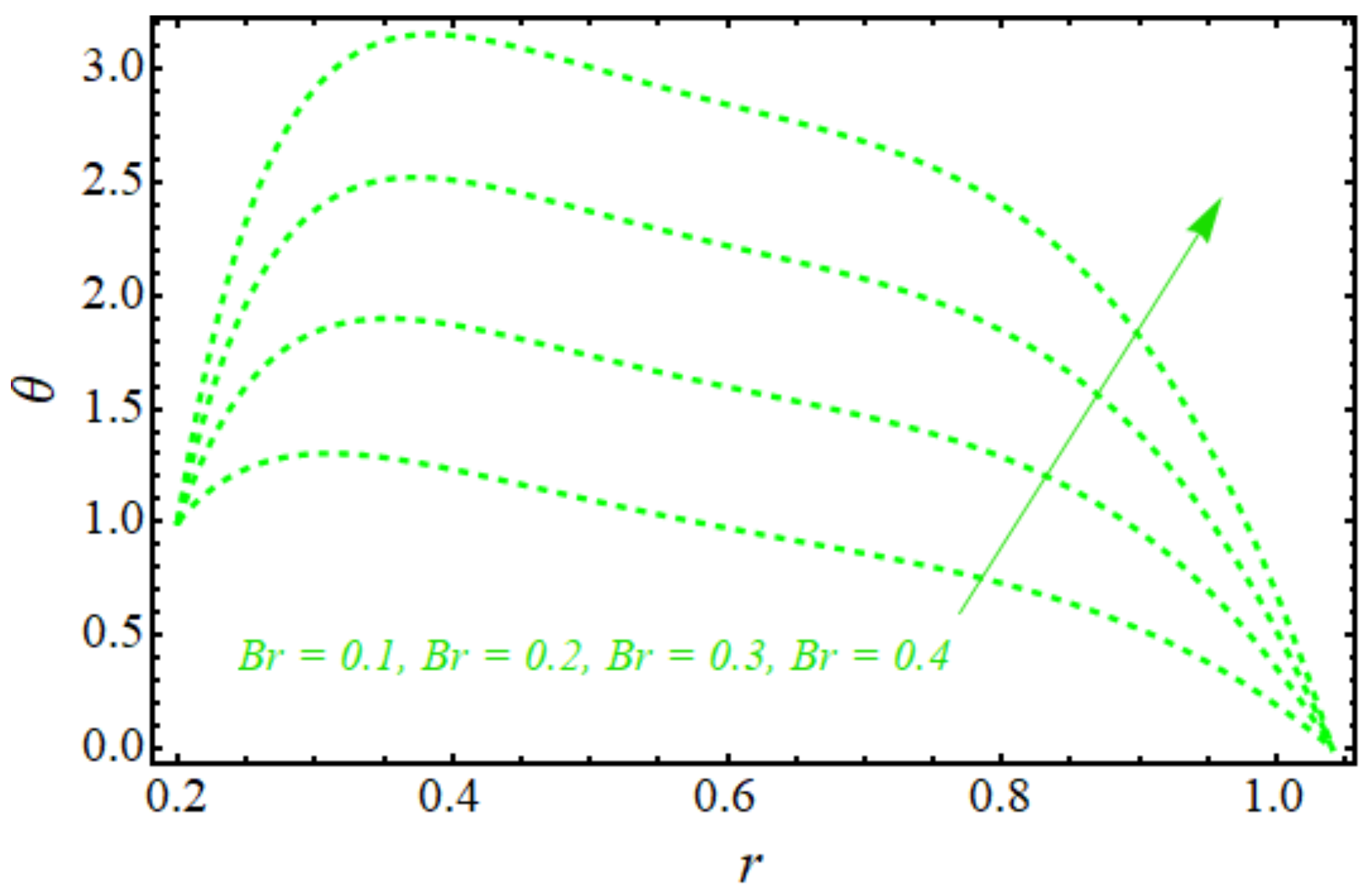
  • It is found that beating cilia produce large temperature differences between the lower wall and the upper wall by increasing the viscous dissipation magnitude.
  • It is also noted that the nanofluid executes a greater heat transfer rate in the case of the viscous dissipation term, which is decided by comparing the results with a previous study.
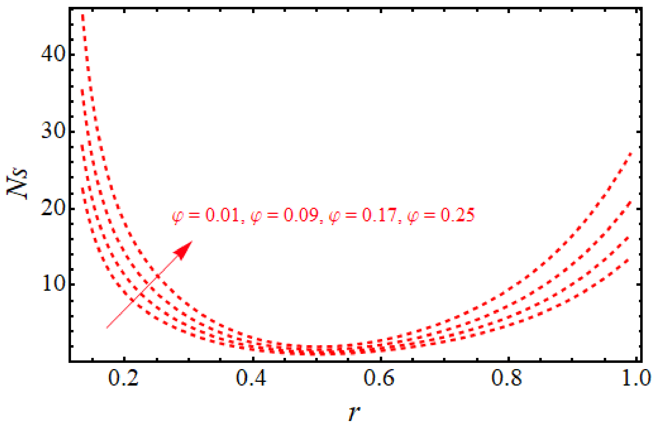
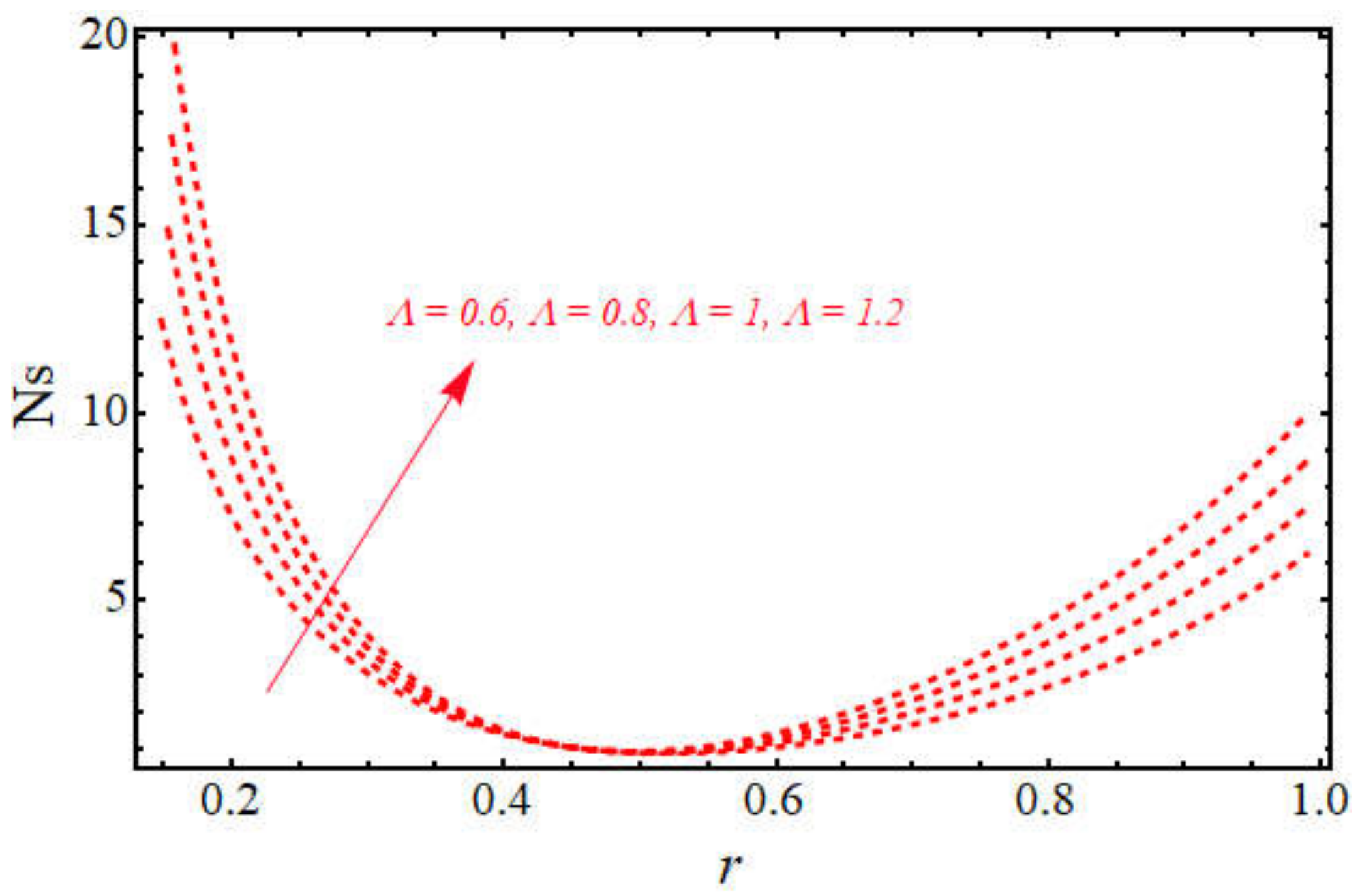
  • Furthermore, we come to the fact that a large amount of viscous dissipation produces a lot of entropy in the flow, and entropy is an increasing function of the flow rate.
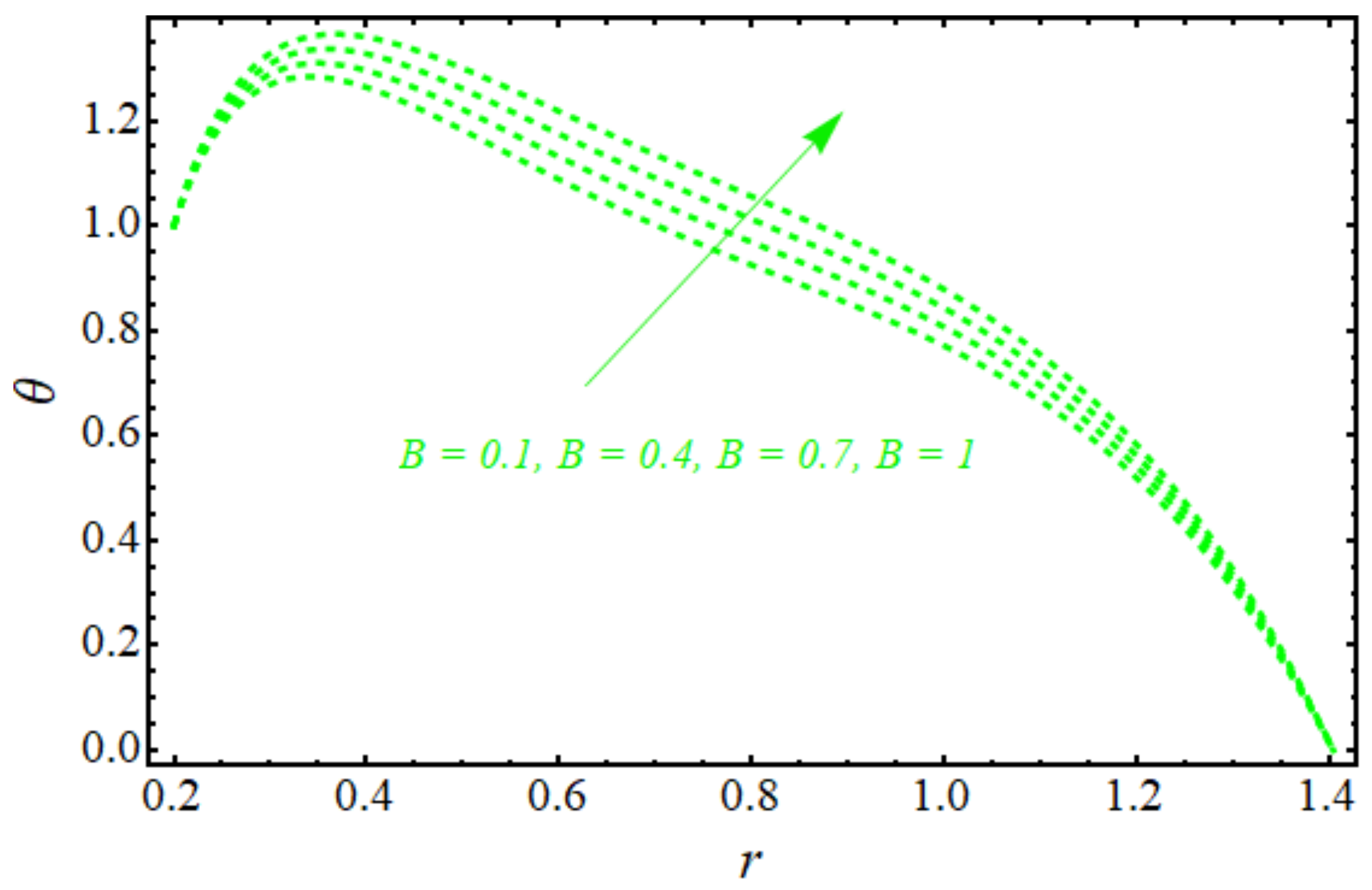
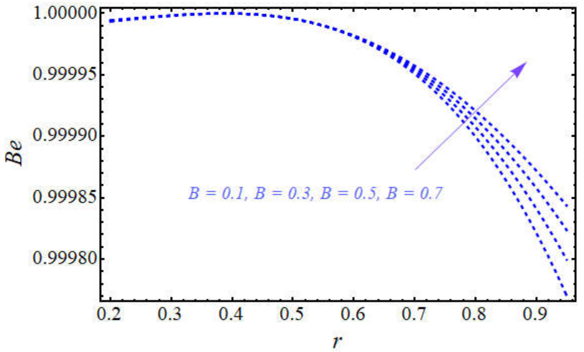
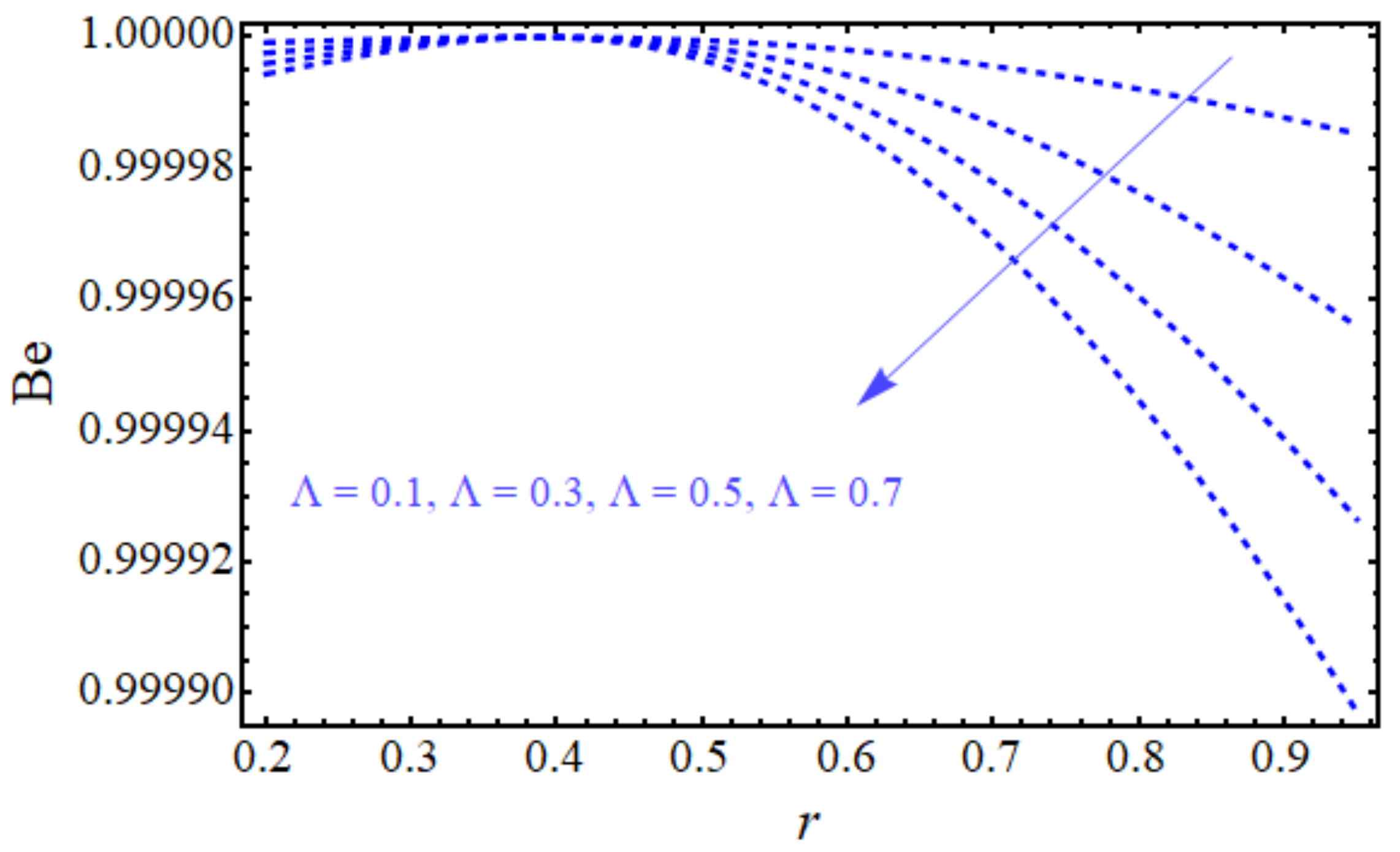
  • It can be stated from the figures that the rate of entropy due to the heat phenomenon is greater than that due to the total entropy of the system in the case when we enhance the values of the heat source constant, B.
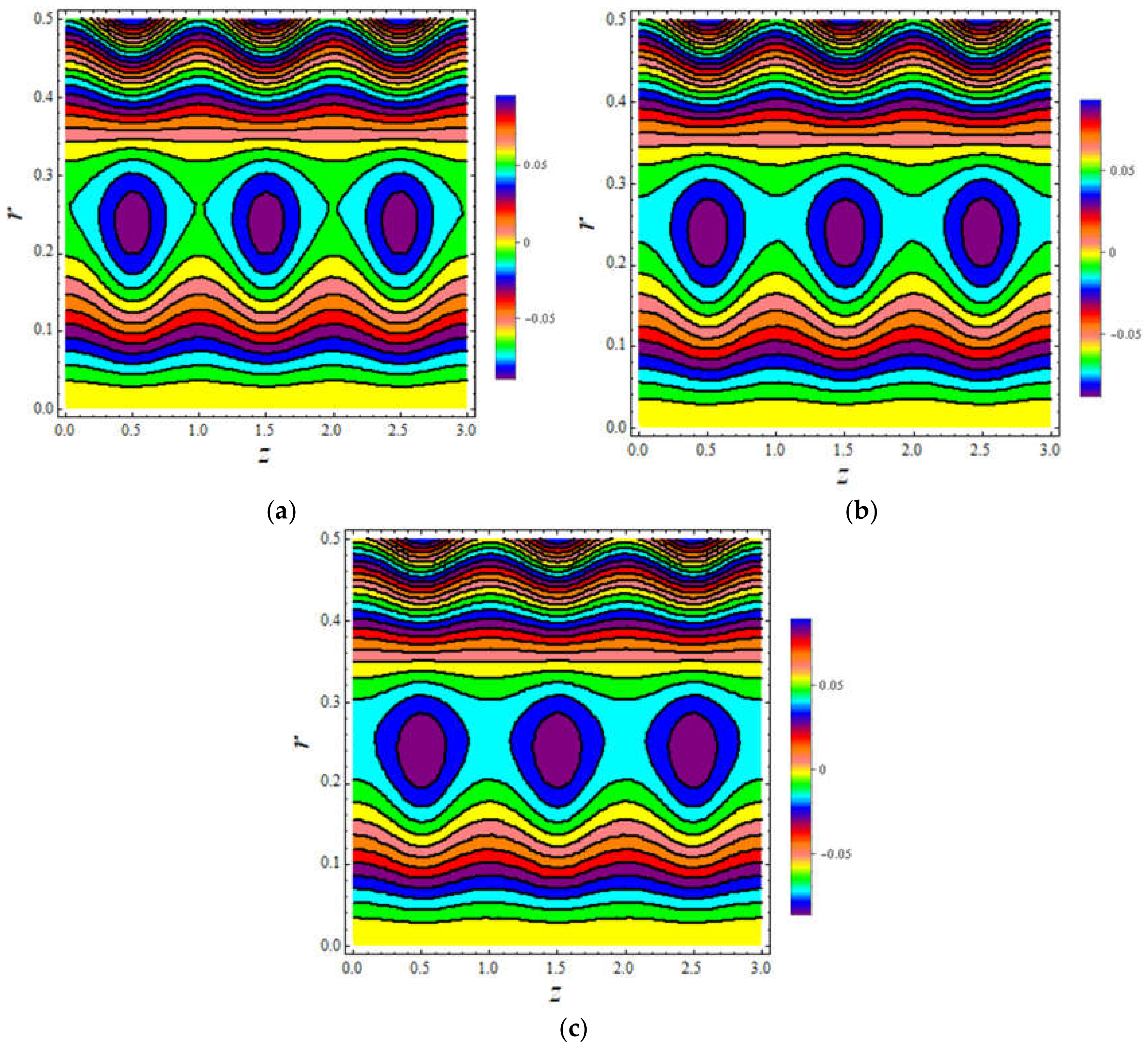
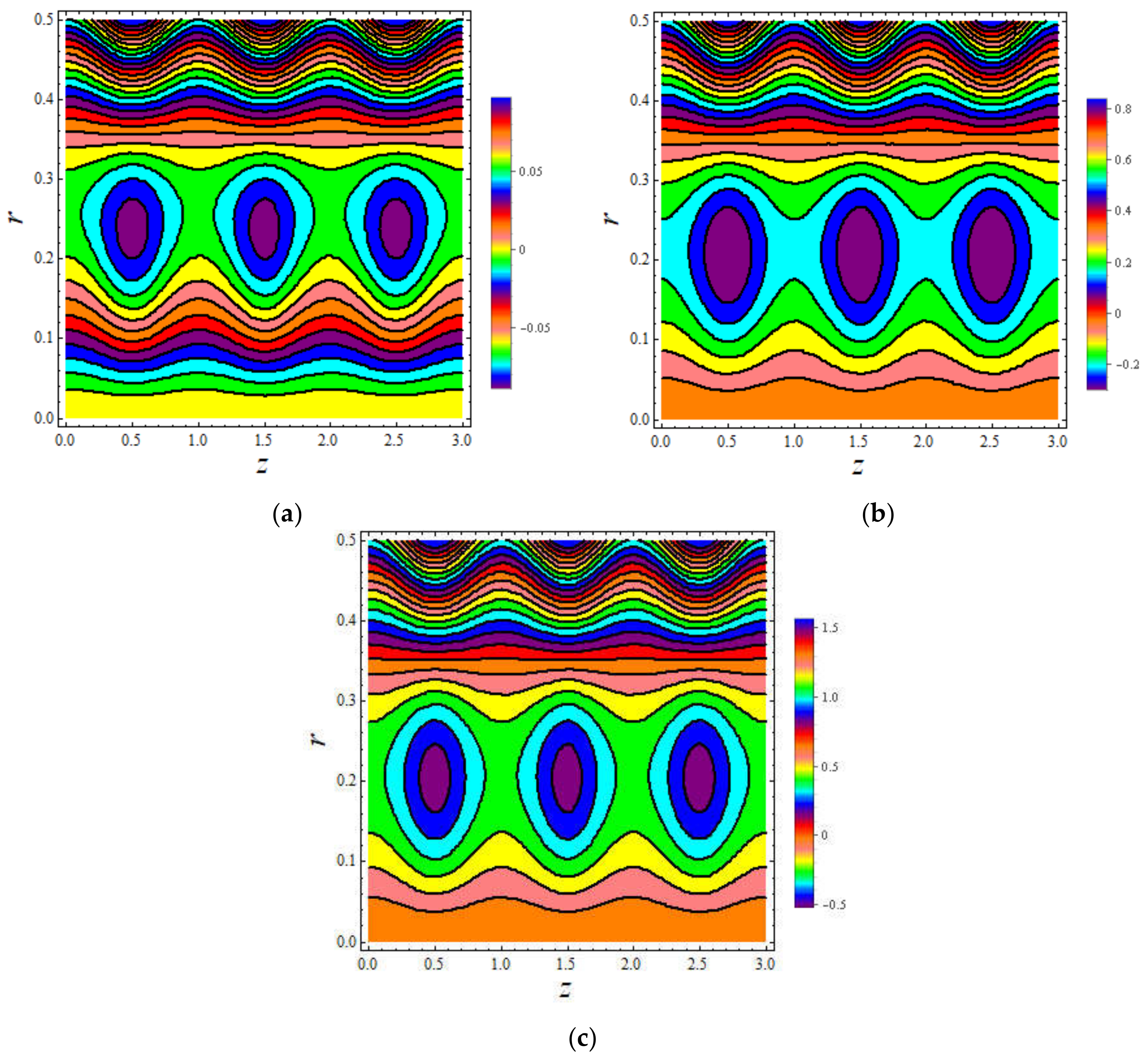
  • From streamlines, it is found that due to the viscous dissipation, large contours are produced, which reflect the lesser speed of the nanofluid due to the dissipation effects.

Author Contributions

Conceptualization, R.E.; investigation, E.B.; methodology, K.R.; validation, A.R.; writing—original draft, A.R. All authors have read and agreed to the published version of the manuscript.

Funding

This research received no external funding.

Institutional Review Board Statement

Not applicable.

Informed Consent Statement

Not applicable.

Data Availability Statement

Not applicable.

Acknowledgments

A. Riaz is very thankful to the University of Education for providing the proper environment to carry our research work.

Conflicts of Interest

The authors declare no conflict of interest.

Appendix A

b 1 = α f α n f ,   b 2 = ρ c p f ρ c p n f ,   b 3 = B b 1 b 2 ,   b 6 = μ n f μ f ,   c 1 = d p / d z r 1 2 d p / d z r 2 2 8 b 6 π α δ ϵ Cos 2 π z 4 b 6 Log r 1 r 2 ,
c 2 = 4 b 6 Log r 1 + d p / d z r 2 2 Log r 1 + 8 b 6 π α δ ϵ Cos 2 π z Log r 1 4 b 6 Log r 2 d p / d z r 1 2 Log r 2 4 b 6 Log r 1 r 2 ,
c 3 = 1 Log r 1 r 2 ( 1 r 1 2 b 1 b 2 Br d p / d z 16 b 6 c 1 + d p / d z r 1 2 + 8 b 3 b 6 2 1 φ 5 / 2 32 b 6 2 1 φ 5 / 2 + r 2 2 b 1 b 2 Br d p / d z 16 b 6 c 1 + d p / d z r 2 2 + 8 b 3 b 6 2 1 φ 5 / 2 32 b 6 2 1 φ 5 / 2 b 1 b 2 Br c 1 2 Log r 1 2 1 φ 5 / 2 + b 1 b 2 Br c 1 2 Log r 2 2 1 φ 5 / 2 ) ,
c 4 = r 2 2 b 1 b 2 Br d p / d z 16 b 6 c 1 + d p / d z r 2 2 + 8 b 3 b 6 2 1 φ 5 / 2 32 b 6 2 1 φ 5 / 2 + b 1 b 2 Br c 1 2 Log r 2 2 1 φ 5 / 2 + 1 Log r 1 r 2 Log r 2 1 r 1 2 b 1 b 2 Br d p / d z 16 b 6 c 1 + d p / d z r 1 2 + 8 b 3 b 6 2 1 φ 5 / 2 32 b 6 2 1 φ 5 / 2 + r 2 2 b 1 b 2 Br d p / d z 16 b 6 c 1 + d p / d z r 2 2 + 8 b 3 b 6 2 1 φ 5 / 2 32 b 6 2 1 φ 5 / 2 b 1 b 2 Br c 1 2 Log r 1 2 1 φ 5 / 2 + b 1 b 2 Br c 1 2 Log r 2 2 1 φ 5 / 2

References

  1. Maxwell, J.C. A Treatise on Electricity and Magnetism, 2nd ed.; Clarendon Press: Oxford, UK, 1873; p. 1. [Google Scholar]
  2. Ganji, D.D.; Malvandi, A. Heat Transfer Enhancement using Nanofluid Flow in Microchannels: Simulation of Heat and Mass Transfer; William Andrew: Amsterdam, The Netherlands, 2016. [Google Scholar]
  3. Waini, I.; Ishak, A.; Pop, I. Hybrid nanofluid flow towards a stagnation point on a stretching/shrinking cylinder. Sci. Rep. 2020, 10, 9296. [Google Scholar] [CrossRef] [PubMed]
  4. Mahdavi, M.; Sharifpur, M.; Ahmadi, M.H.; Meyer, J.P. Nanofluid flow and shear layers between two parallel plates: A simulation approach. Eng. Appl. 2020, 14, 1536–1545. [Google Scholar] [CrossRef]
  5. Gul, T.; Gul, R.S.; Noman, W.; Saeed, A.; Mukhtar, S.; Alghamdi, W.; Alrabaiah, H. CNTs-nanofluid flow in a rotating system between the gap of a disk and cone. Phys. Scr. 2020, 95, 125202. [Google Scholar] [CrossRef]
  6. Tassaddiq, A.; Khan, S.; Bilal, M.; Gul, T.; Mukhtar, S.; Shah, Z.; Bonyah, E. Heat and mass transfer together with hybrid nanofluid flow over a rotating disk. AIP Adv. 2020, 10, 055317. [Google Scholar] [CrossRef]
  7. Ramzan, M.; Chung, J.D.; Kadry, S.; Chu, Y.M.; Akhtar, M. Nanofluid flow containing carbon nanotubes with quartic autocatalytic chemical reaction and Thompson and Troian slip at the boundary. Sci. Rep. 2020, 10, 18710. [Google Scholar]
  8. Eid, M.R.; Mabood, F.; Mahny, K.L. On 3D Prandtl nanofluid flow with higher-order chemical reaction. Proc. Inst. Mech. Eng. Part C J. Mech. Eng. Sci. 2020, 235, 0954406220975429. [Google Scholar] [CrossRef]
  9. Eid, M.R. Effects of NP shapes on non-Newtonian bio-nanofluid flow in suction/blowing process with convective condition: Sisko model. J. Non-Equil. Thermodyn. 2020, 45, 97–108. [Google Scholar] [CrossRef]
  10. Mondal, S.K.; Pal, D. Computational analysis of bioconvective flow of nanofluid containing gyrotactic microorganisms over a nonlinear stretching sheet with variable viscosity using HAM. J. Comput. Des. Eng. 2020, 7, 251–267. [Google Scholar] [CrossRef] [Green Version]
  11. Warke, A.S.; Ramesh, K.; Mebarek-Oudina, F.; Abidi, A. Numerical investigation of the stagnation point flow of radiative magnetomicropolar liquid past a heated porous stretching sheet. J. Therm. Anal. Calorim. 2021, 1–12. [Google Scholar] [CrossRef]
  12. Pushpa, B.V.; Sankar, M.; Mebarek-Oudina, F. Buoyant convective flow and heat dissipation of cu–h2o nanoliquids in an annulus through a thin baffle. J. Nanofluids 2021, 10, 292–304. [Google Scholar] [CrossRef]
  13. Marzougui, S.; Mebarek-Oudina, F.; Magherbi, M.; Mchirgui, A. Entropy generation and heat transport of Cu–water nanoliquid in porous lid-driven cavity through magnetic field. Int. J. Numer. Methods Heat Fluid Flow 2021. [Google Scholar] [CrossRef]
  14. Mebarek-Oudina, F.; Fares, R.; Aissa, A.; Lewis, R.W.; Abu-Hamdeh, N.H. Entropy and convection effect on magnetized hybrid nano-liquid flow inside a trapezoidal cavity with zigzagged wall. Int. Commun. Heat Mass Transf. 2021, 125, 105279. [Google Scholar] [CrossRef]
  15. Shafiq, A.; Mebarek-Oudina, F.; Sindhu, T.N.; Abidi., A. A study of dual stratification on stagnation point Walters’ B nanofluid flow via radiative Riga plate: A statistical approach. Eur. Phys. J. Plus. 2021, 136, 407. [Google Scholar] [CrossRef]
  16. Arain, M.B.; Bhatti, M.M.; Zeeshan, A.; Alzahrani, F.S. Bioconvection reiner-rivlin nanofluid flow between rotating circular plates with induced magnetic effects, activation energy and squeezing phenomena. Mathematics 2021, 9, 2139. [Google Scholar] [CrossRef]
  17. Goodarzi, M.; Tlili, I.; Moria, H.; Cardoso, E.M.; Alkanhal, T.A.; Anqi, A.E.; Safaei, M.R. Boiling flow of graphene nanoplatelets nano-suspension on a small copper disk. Powder Technol. 2021, 377, 10–19. [Google Scholar] [CrossRef]
  18. Goggolidou, P. (Ed.) Cilia: Development and Disease; CRC Press: Boca Raton, FL, USA, 2018. [Google Scholar]
  19. Sadaf, H.; Nadeem, S. Influences of slip and Cu-blood nanofluid in a physiological study of cilia. Comput. Methods Programs Biomed. 2016, 131, 169–180. [Google Scholar] [CrossRef] [PubMed]
  20. Shaheen, S.; Maqbool, K.; Siddiqui, A.M. Micro rheology of Jeffrey nanofluid through cilia beating subject to the surrounding temperature. Rheol. Acta 2020, 59, 565–573. [Google Scholar] [CrossRef]
  21. Imran, A.; Akhtar, R.; Zhiyu, Z.; Shoaib, M.; Raja, M.A.Z. Heat transfer analysis of biological nanofluid flow through ductus efferentes. AIP Adv. 2020, 10, 035029. [Google Scholar] [CrossRef] [Green Version]
  22. Nadeem, S.; Sadaf, H. Trapping study of nanofluids in an annulus with cilia. AIP Adv. 2015, 5, 127204. [Google Scholar] [CrossRef] [Green Version]
  23. Nadeem, S.; Sadaf, H. Ciliary motion phenomenon of viscous nanofluid in a curved channel with wall properties. Eur. Phys. J. Plus. 2016, 131, 65. [Google Scholar] [CrossRef]
  24. Nadeem, S.; Sadaf, H. Theoretical analysis of Cu-blood nanofluid for metachronal wave of cilia motion in a curved channel. IEEE Trans. Nanobiosci. 2015, 14, 447–454. [Google Scholar] [CrossRef] [PubMed]
  25. Javid, K.; Ali, N.; Bilal, M. A numerical simulation of the creeping flow of TiO2-SiO2/C2H6O2 hybrid-nano-fluid through a curved configuration due to metachronal waves propulsion of beating cilia. Eur. Phys. J. Plus. 2020, 135, 49. [Google Scholar] [CrossRef]
  26. Awais, M.; Shah, Z.; Perveen, N.; Ali, A.; Kumam, P.; Thounthong, P. MHD effects on ciliary-induced peristaltic flow coatings with rheological hybrid nanofluid. Coatings 2020, 10, 186. [Google Scholar] [CrossRef] [Green Version]
  27. Maqbool, K.; Shaheen, S.; Siddiqui, A.M. Effect of nano-particles on MHD flow of tangent hyperbolic fluid in a ciliated tube: An application to fallopian tube. Math. Biosci. Eng. 2019, 16, 2927–2941. [Google Scholar] [CrossRef] [PubMed]
  28. Akbar, N.S.; Tripathi, D.; Khan, Z.H.; Bég, O.A. Mathematical model for ciliary-induced transport in MHD flow of Cu-H2O nanofluids with magnetic induction. Chin. J. Phys. 2017, 55, 947–962. [Google Scholar] [CrossRef]
  29. Abrar, M.N.; Haq, R.U.; Awais, M.; Rashid, I. Entropy analysis in a cilia transport of nanofluid under the influence of magnetic field. Nucl. Eng. Technol. 2017, 49, 1680–1688. [Google Scholar] [CrossRef]
  30. Awan, S.E.; Awais, M.; Raja, M.A.Z.; Parveen, N.; Ali, H.M.; Khan, W.U.; He, Y. Numerical treatment for dynamics of second law analysis and magnetic induction effects on ciliary induced peristaltic transport of hybrid nanomaterial. Front. Phys. 2021, 9, 68. [Google Scholar] [CrossRef]
  31. Abrar, M.N.; Sagheer, M.; Hussain, S. Entropy generation during peristaltically flowing nanofluid in an axisymmetric channel with flexible walls. Phys Scr. 2020, 95, 035206. [Google Scholar] [CrossRef]
  32. Bhatti, M.M.; Elelamy, A.F.; Sait, S.M.; Ellahi, R. Hydrodynamics Interactions of Metachronal Waves on Particulate-Liquid Motion through a Ciliated Annulus: Application of Bio-Engineering in Blood Clotting and Endoscopy. Symmetry 2020, 12, 532. [Google Scholar] [CrossRef] [Green Version]
  33. Ahmad Farooq, A.; Shah, Z.; Alzahrani, E.O. Heat Transfer Analysis of a Magneto-Bio-Fluid Transport with Variable Thermal Viscosity Through a Vertical Ciliated Channel. Symmetry 2019, 11, 1240. [Google Scholar] [CrossRef] [Green Version]
  34. Munawar, S.; Saleem, N. Second Law Analysis of Ciliary Pumping Transport in an Inclined Channel Coated with Carreau Fluid under a Magnetic Field. Coatings 2020, 10, 240. [Google Scholar] [CrossRef] [Green Version]
  35. Bejan, A. A study of entropy generation in fundamental convective heat transfer. J. Heat Transfer. 1979, 101, 718–725. [Google Scholar] [CrossRef]
  36. Pakdemirli, M.; Yilbas, B.S. Entropy generation in a pipe due to non-Newtonian fluid flow: Constant viscosity case. Sadhana 2006, 31, 21–29. [Google Scholar] [CrossRef] [Green Version]
  37. Aïboud, S.; Saouli, S. Entropy analysis for viscoelastic magnetohydrodynamic flow over a stretching surface. Int. J. Non Linear Mech. 2010, 45, 482–489. [Google Scholar] [CrossRef]
  38. Sheikholeslami, M.; Ellahi, R.; Shafee, A.; Li, Z. Numerical investigation for second law analysis of ferrofluid inside a porous semi annulus: An application of entropy generation and exergy loss. Int. J. Numer. Methods Heat Fluid Flow 2019, 29, 1079–1102. [Google Scholar] [CrossRef]
  39. Galanis, N.; Rashidi, M.M. Entropy generation in non-Newtonian fluids due to heat and mass transfer in the entrance region of ducts. Heat Mass Transf. 2012, 48, 1647–1662. [Google Scholar] [CrossRef]
  40. Rashidi, M.M.; Parsa, A.B.; Beg, O.A.; Shamekhi, L.; Sadri, S.M.; Bég, T.A. Parametric analysis of entropy generation in magneto-hemodynamic flow in a semi-porous channel with OHAM and DTM. Appl. Bionics Biomech. 2014, 11, 47–60. [Google Scholar] [CrossRef] [Green Version]
  41. Ellahi, R.; Sait, S.M.; Shehzad, N.; Ayaz, Z. A hybrid investigation on numerical and analytical solutions of electro-magnetohydrodynamics flow of nanofluid through porous media with entropy generation. Int. J. Numer. Methods Heat Fluid Flow 2019, 30, 834–854. [Google Scholar] [CrossRef]
  42. Bhatti, M.M.; Abbas, T.; Rashidi, M.M.; Ali, M.E.S. Numerical simulation of entropy generation with thermal radiation on MHD Carreaunanofluid towards a shrinking sheet. Entropy 2016, 18, 200. [Google Scholar] [CrossRef] [Green Version]
  43. AbdollahzadehJamalabadi, M.Y.; Hooshmand, P.; Hesabi, A.; Kwak, M.K.; Pirzadeh, I.I.; Keikha, A.J.; Negahdari, M. Numerical investigation of thermal radiation and viscous effects on entropy generation in forced convection blood flow over an axisymmetric stretching sheet. Entropy 2016, 18, 203. [Google Scholar] [CrossRef] [Green Version]
  44. Upreti, H.; Pandey, A.K.; Kumar, M. Assessment of entropy generation and heat transfer in three-dimensional hybrid nanofluids flow due to convective surface and base fluids. J. Porous Media 2021, 24, 35–50. [Google Scholar] [CrossRef]
Figure 1. Geometry of the flow.
Symmetry 13 02358 g001
Figure 2. Temperature distribution for B. The fixed quantities are φ = 0.1 ,   α = 0.32 ,   δ = 0.11 ,   ξ = 0.2 ,   z = 0.1 ,   ε = 0.5 ,   Q = 1   and   B r = 0.17 .
Symmetry 13 02358 g002
Figure 3. Temperature distribution for B r . The fixed quantities are φ = 0.01 ,   α = 0.32 ,   δ = 0.11 ,   ξ = 0.2 ,   z = 0.1 ,   ε = 0.05 ,   Q = 1   and   B = 0.17 .
Symmetry 13 02358 g003
Figure 4. Temperature distribution for ξ . The fixed quantities are φ = 0.1 ,   α = 0.32 ,   δ = 0.11 ,   B = 0.2 ,   z = 0.1 ,   ε = 0.5 ,   Q = 1   and   B r = 0.17 .
Symmetry 13 02358 g004
Figure 5. Temperature profile for ϕ . The fixed parameters are B r = 0.01 ,   α = 0.32 ,   δ = 0.11 ,   ξ = 0.2 ,   z = 0.1 ,   ε = 0.05 ,   Q = 1   and   B = 0.17 .
Symmetry 13 02358 g005
Figure 6. Entropy rate for B. The fixed factors are B r = 0.05 ,   α = 0.1 ,   δ = 0.9 ,   ξ = 0.1 ,   z = 0.5 ,   ε = 0.01 ,   Q = 1 ,   φ = 0.1   and   Λ = 0.5 .
Symmetry 13 02358 g006
Figure 7. Entropy rate for B r . The fixed factors are B = 0.2 ,   α = 0.1 ,   δ = 0.9 ,   ξ = 0.1 ,   z = 0.5 ,   ε = 0.01 ,   Q = 0.5 ,   φ = 0.01   and   Λ = 0.7 .
Symmetry 13 02358 g007
Figure 8. Entropy rate for ϕ . The fixed factors are B r = 0.05 ,   α = 0.1 ,   δ = 0.9 ,   ξ = 0.1 ,   z = 0.5 ,   ε = 0.01 ,   Q = 1 ,   B = 0.2   and   Λ = 0.5 .
Symmetry 13 02358 g008
Figure 9. Entropy rate for Q . The fixed factors are B r = 0.05 ,   α = 0.1 ,   δ = 0.9 ,   ξ = 0.1 ,   z = 0.5 ,   ε = 0.01 ,   B = 0.2 ,   φ = 0.01   and   Λ = 0.5 .
Symmetry 13 02358 g009
Figure 10. Entropy rate for Λ . The fixed factors are B r = 0.1 ,   α = 0.1 ,   δ = 0.9 ,   ξ = 0.1 ,   z = 0.5 ,   ε = 0.01 ,   Q = 0.5 ,   φ = 0.01   and   B = 0.2 .
Symmetry 13 02358 g010
Figure 11. Bejan number for B . The unaltered ingredients are B r = 0.1 ,   α = 0.1 ,   δ = 0.2 ,   ξ = 0.2 ,   z = 0.5 ,   ε = 0.05 ,   Q = 0.05 ,   φ = 0.1   and   Λ = 0.9 .
Symmetry 13 02358 g011
Figure 12. Bejan number for Λ . The unaltered ingredients are B r = 0.1 ,   α = 0.1 ,   δ = 0.2 ,   ξ = 0.2 ,   z = 0.5 ,   ε = 0.05 ,   Q = 0.05 ,   φ = 0.1   and   B = 1.0 .
Symmetry 13 02358 g012
Figure 13. (ac): Bolus curve for α .
Symmetry 13 02358 g013
Figure 14. (ac): Bolus curves for ϵ .
Symmetry 13 02358 g014
Figure 15. (ac): Bolus curves for flow rate, Q.
Symmetry 13 02358 g015
Table 1. Comparison of temperature variation, θ , with the work of [22].
Current   Study   with   B r   =   0 [22] Current   Study   with   B r   =   0.4
1 1 1
1.25296 1.25297 1.29555
1.07354 1.07355 1.1313
0.910609 0.91061 0.968761
0.759397 0.759398 0.807133
0.512767 0.512765 0.541041
0.0155143 0.0155141 0.0162243
0.922397 0.922399 0.956793
2.52182 2.52181 2.5985
5.03306 5.03303 5.15896
Publisher’s Note: MDPI stays neutral with regard to jurisdictional claims in published maps and institutional affiliations.

