Article

Analytical Prediction of Stretch-Bending Springback Based on the Proportional Kinematic Hardening Model

Key Laboratory of Advanced Forging & Stamping Technology and Science, Yanshan University, Ministry of Education of China, Qinhuangdao 066004, China
*
Author to whom correspondence should be addressed.
Symmetry 2021, 13(12), 2389; https://doi.org/10.3390/sym13122389
Submission received: 9 November 2021 / Revised: 5 December 2021 / Accepted: 6 December 2021 / Published: 11 December 2021
(This article belongs to the Special Issue Symmetry/Asymmetry in Metal Forming)

Abstract

:
Pre-stretching and post-bending are the simplest loading methods for the profile stretch-bending technical process. The inner layers of the profile are stretched and then compressed during the loading process. Considering the Bauschinger effect of metal materials, a new material model called the proportional kinematic hardening model was proposed. The stretch-bending mechanical model was established under a pre-stretching and post-bending loading path. The stress and strain on the cross section of profiles were analyzed. The analytic expressions of curvature radius of the strain neutral layer and bending moment were derived after loading. The analytic method for determining the curvature radius of the geometric center layer after unloading and springback during stretch-bending was established. The rectangular section ST12 profile with symmetrical characteristics is adopted, the stretch-bending experimental results show that the new proportional kinematic hardening model is more accurate than the classical kinematic hardening model in predicting the stretch-bending springback.

1. Introduction

Many bent profiles in structures such as buildings, aircraft and automobiles are manufactured by a stretch-bending technical process. Accurate prediction of springback is an inevitable problem. At present, the research methods of stretch-bending springback mainly include theoretical analysis, numerical simulation and physical experiment.
The plane bending springback equation was established based on the bilinear material model and provided a method for the analysis of stretch-bending springback [1]. Ma and Elsharkawy studied the variation law of bending moment during stretch-bending with exponential hardening material model [2,3]. In addition, many scholars have studied the law of stretch-bending springback of profiles with some typical cross section by using an exponential hardening material model [4,5,6,7,8,9,10]. Based on the classical kinematic hardening material model, Zhai established a general plane stretch-bending springback equation, and the effect of the Bauschinger effect on springback is considered [11,12].
The law of stretch-bending springback of aluminum alloy profile AA6082 (T5) was studied by experimental method [13]. Uemori and Naka described the effects of temperature and loading speed on springback in stretch-bending of high strength steel profiles by experimental method [14,15]. A new “rubber-assisted stretch bending method” was established by Muranaka [16] and the springback decreased by 21% in comparison with the crank motion simple bending by using ordinary metal dies. The composites prepared by Etemadi in the fifth cumulative pressure welding cycle have good tensile strength and large elastic modulus, which greatly reduces the amount of springback [17]. Lamanna [18], Bjorkhaug [19] and Li [20] used the finite element method to study the stretch-bending process, and obtained the springback law consistent with the experiment. Huang [21,22] solved the problem of large ellipse of large thin-walled tube by combining theoretical calculation, numerical simulation and physical experiment.
In the process of stretch-bending, unloading and reverse loading are inevitable in inner layers of profile, the Bauschinger effect of metal material cannot be ignored when reverse plastic deformation occurs. Traditionally, there are few studies on the influence of the Bauschinger effect on stretch-bending springback, and the accuracy of material model used in analytical prediction is not high. In order to improve the analytical accuracy and to facilitate the engineering application, a more rigorous constitutive relation of the proportion kinematic hardening model and a more accurate mechanical analysis method are proposed in this article. The new model is verified by experiments.

2. Mechanical Model of Profile Stretch-Bending and Springback Analytical Method

2.1. Research Object

Figure 1 is shown as the geometric diagram of any asymmetric section profile. The geometric center o of the profile is set as the origin of the coordinate system u v w . In the coordinate system, the longitudinal section u o w represents the bending plane formed by stretch-bending. The coordinate axis w is always perpendicular to the cross section of profile in the whole forming process. In the bending plane, the intersection of the outermost layer and the axis u is set as point A, and the innermost intersection is B. The section height is set as h and the width of the section is B ( u ) , which changes with the coordinate value u .
Figure 2 is the schematic diagram of stretch-bending loading. During stretch-bending, it must be ensured that the tensile force at the cross section of the profile is equal, and the axial tensile force direction during bending is always consistent with the tangent direction of the geometric central axis of the profile. ρ represents the bending radius of the geometric center layer of the profile, R represents the bending die radius, M represents the total bending moment of the profile after stretch-bending deformation, and ρ = R + h c .

2.2. Basic Hypothesis

(1)
Plane section assumption: It is assumed that the cross section of profiles before and after stretch-bending loading is planar and perpendicular to the geometrical central axis of the profile.
(2)
Uniaxial stress assumption: In the process of stretch- bending, it is assumed that every fiber along axis w is in uniaxial tension or uniaxial compression state.
(3)
Bilinear material model hypothesis: in the stretch-bending process, it is assumed that stress–strain relationship of the elastic deformation and plastic deformation are both linear.
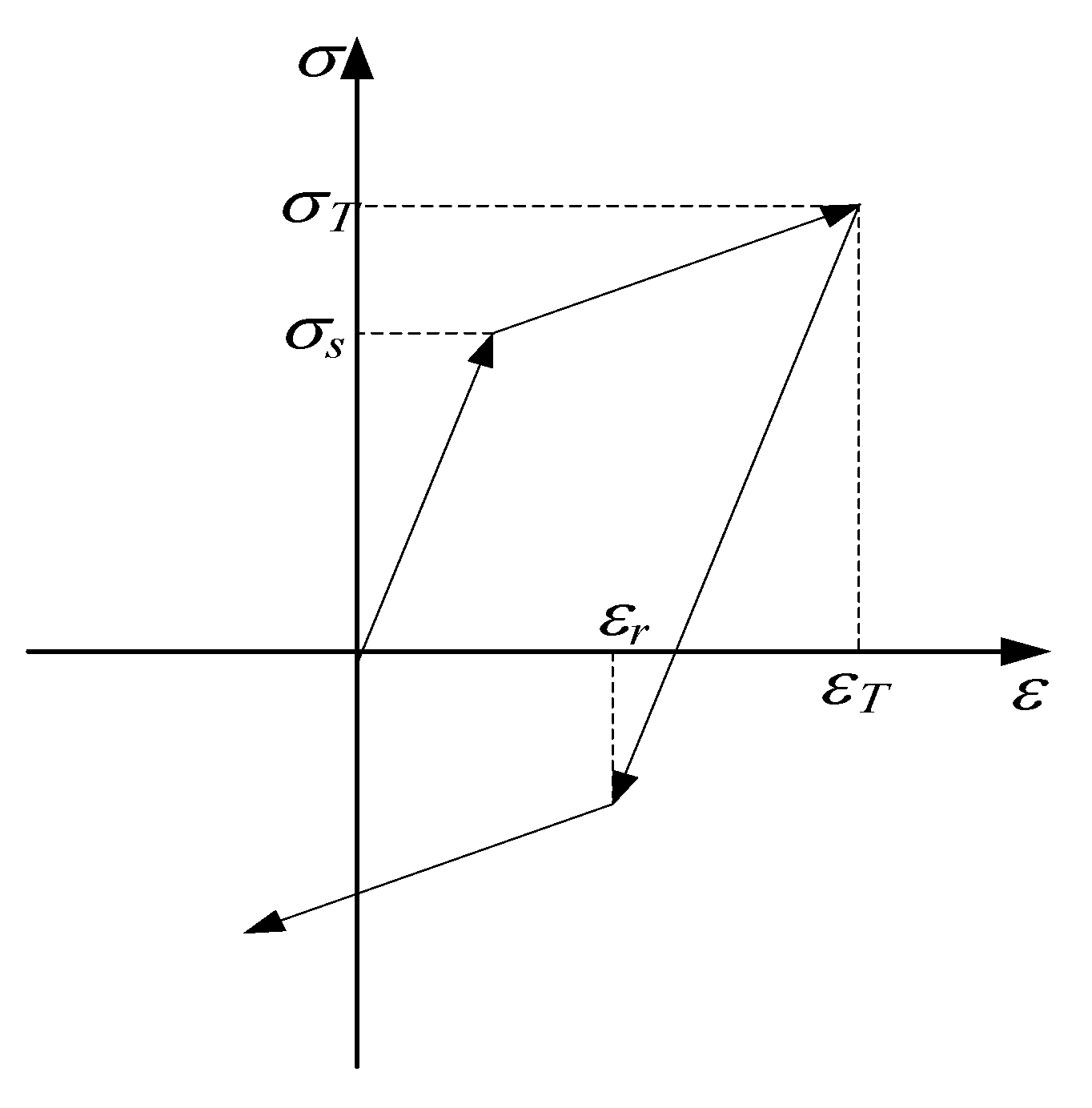
2.3. Material Model

Based on the base hypothesis (3), the relationship of stress and strain is as shown in Figure 3. In the past, in the classical kinematic hardening material model, the yield point under reverse loading was approximately expressed as: σ r = σ T 2 σ s . In this article, a new proportional kinematic hardening model was established, and the yield point under reverse loading was accurately expressed as: σ r = λ σ T . λ is called the proportional coefficient of reverse yield. When unloading and reverse loading, considering the Bauschinger effect of the material, the stress–strain relationship under unidirectional loading is as follows:
σ = { E · ε ε ε s σ s + D · ( ε ε s ) ε > ε s
where, σ and ε stand for stress and strain, E and D stand for the modulus of elasticity and the modulus of plasticity, ε s stands for elastic limit strain, and σ s = ε s · E . σ T and ε T are the stress and strain of plastic pre-stretch, ε r is the strain at the yield point of reverse loading.

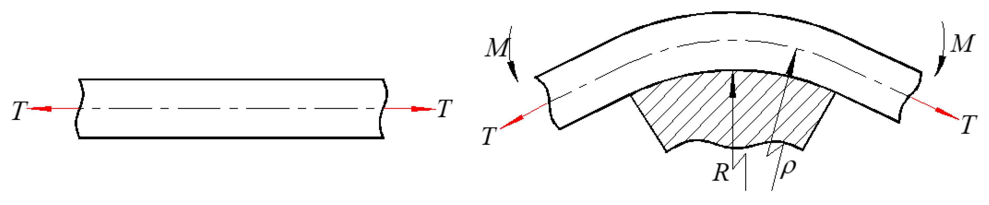
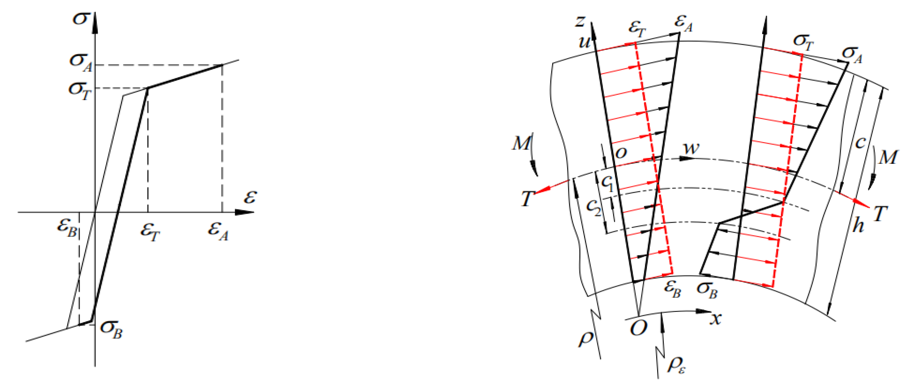
2.4. Mechanical Model of Stretch-Bending Loading

When the initial tensile stress is greater than the yield stress of the material, all the fiber layers in the cross section of the material have a plastic tensile deformation. In the subsequent bending process, when the bending radius is small, the inner fiber will appear as a reverse compression yield, as shown in Figure 4. σ T is the stress of plastic pre-stretch, and c 1 is the distance from the boundary point of plastic tensile deformation zone and elastic unloading deformation zone of profile to the geometric center layer. c 2 is the distance from the boundary point of plastic compression deformation zone and elastic unloading deformation zone of profile to the geometric center layer. σ A and ε A are the stress and strain of the outermost layer of the profile after stretch-bending, σ B and ε B are the stress and strain of the innermost layer of the profile after stretch-bending. The radius of curvature of the strain neutral layer is ρ ε , and the radius of curvature of the geometric center layer is ρ . After stretch-bending, the strain neutral layer moves inward. At this time, the coordinate system of the strain neutral layer is x o z and the coordinate system of the geometric center layer is still w o u .
Based on the proportional kinematic hardening model, the expressions of total stress are:
σ = { λ σ T + ( u   +   ρ     ρ ε ρ ε ε T + 1     λ E σ T ) · D c h u c 2 σ T + ( u   +   ρ     ρ ε ρ ε ε T ) · E c 2 u c 1 σ T + ( u   +   ρ     ρ ε ρ ε ε T ) · D c 1 u c
The area of inner layer reverse plastic compression deformation area in cross section of profile is A 1 , the static moment of v axis is S 1 , the moment of inertia to the v axis is I 1 . The area of middle elastic deformation zone is A 2 , the static moment to the v axis is S 2 , the moment of inertia to the v axis is I 2 ; The area of the outer plastic stretched deformation zone is A 3 , the static moment to the v axis is S 3 , the moment of inertia to the v axis is I 3 . The mathematical relationship between the internal stress of the cross section of the profile and the externally applied axial stretch and bending moment in stretch-bending deformation are:
c h c 2 λ σ T + ( u + ρ ρ ε ρ ε ε T + 1 λ E σ T ) · D d A + c 2 c 1 σ T + ( u + ρ ρ ε ρ ε ε T ) · E d A + c 1 c σ T + ( u + ρ ρ ε ρ ε ε T ) · D d A = T
c h c 2 [ λ σ T + ( u + ρ ρ ε ρ ε ε T + 1 λ E σ T ) · D ] · u d A + c 2 c 1 [ σ T + ( u + ρ ρ ε ρ ε ε T ) · E ] · u d A + c 1 c [ σ T + ( u + ρ ρ ε ρ ε ε T ) · D ] · u d A = M
The expressions of curvature radius and total bending moment of strain neutral layer are respectively:
ρ ε = ( S 1 + A 1 ρ ) D + ( S 2 + A 2 ρ ) E + ( S 3 + A 3 ρ ) D ( 1 + ε T ) ( A 1 D + A 2 E + A 3 D ) + [ A A 1 λ A 2 A 3 ( 1 λ ) E A 1 D ] σ T
M = I 1 D + I 2 E + I 3 D ρ ε + ( ρ ρ ε 1 ε T ) ( S 1 D + S 2 E + S 3 D ) + 1 λ E S 1 D + ( λ S 1 + S 2 + S 3 ) σ T
The total strain at the boundary point c 1 is expressed as:
c 1 + ( ρ ρ ε ) ρ ε = ε T
The total strain at the boundary point c 2 is expressed as:
c 2 + ( ρ ρ ε ) ρ ε = ε T 1 λ E σ T
The expressions of curvature radius of strain neutral layer and bending moment can be obtained by simultaneous Equations (5)–(8).

2.5. Analytical Method of Stretch-Bending Springback

Based on the research results of reference [11,12], the analytical method of stretch-bending springback is as follows:
The strain after stretch-bending springback is the superposition of the strain under stretch-bending loading and the strain under reverse elastic loading. The geometric constraint equation of plane stretch-bending springback can be obtained as follows:
{ 1 ρ ε 1 ρ ε e 1 ρ ε p = 0 ρ ρ ε + ρ e ρ ε e ρ p ρ ε p = 1
where, ρ ε e is the curvature radius of strain neutral layer after reverse elastic loading; ρ e is the curvature radius of geometric center layer after reverse elastic loading; ρ ε p is the curvature radius of strain neutral layer after springback; ρ p is the curvature radius of geometric center layer after springback.
The plane stretch-bending springback equation of profile is:
ρ p = ρ T E A ρ ε 1 M E I v ρ ε
According to the plane stretch-bending springback equation of profile, when the profile is given, the cross-sectional area A, the moment of inertia about the cross-section about v axis and the elastic modulus E can be determined. When a certain tensile force T and bending radius ρ are applied to the profile for stretch-bending, the analytical prediction results of the curvature radius of the geometric center layer after the springack of the profile can be obtained only by determining the curvature radius of the strain neutral layer ρ ε and the bending moment M.

3. Determination of Model Parameters of Proportional Kinematic Hardening Materials

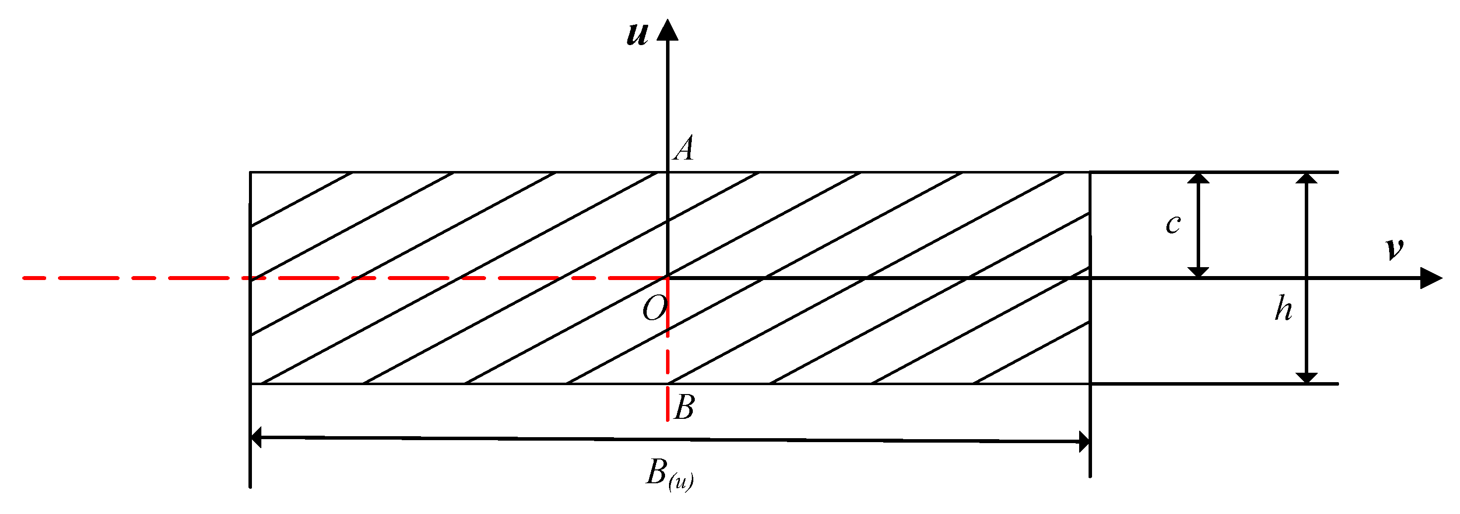
3.1. Geometric Parameters of Profile Cross Section

In order to verify the correctness and accuracy of the theoretical methods, the rectangular section ST12 profile with symmetrical characteristics is adopted. Figure 5 shows the schematic diagram of rectangular section profile, and the geometric dimensions of rectangular section profile are shown in Table 1.

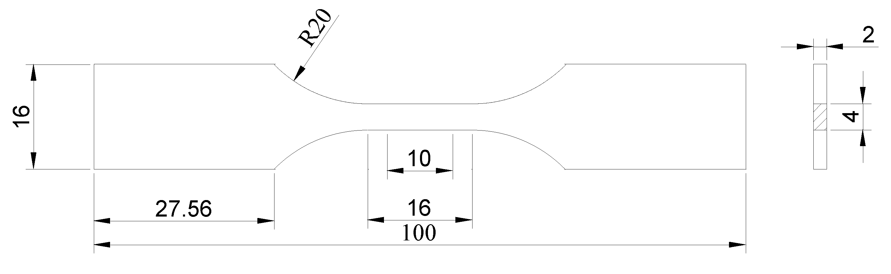
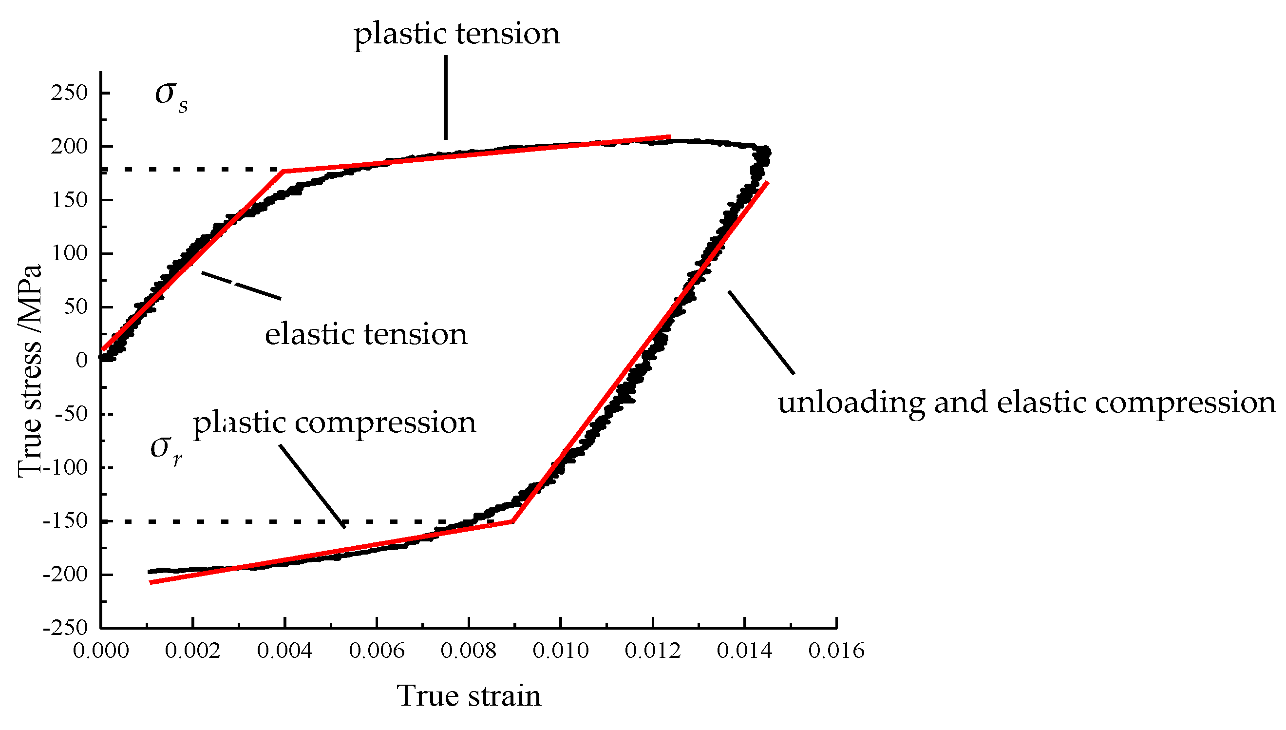
3.2. Determination of Material Mechanical Property Parameters and Proportional Kinematic Hardening Model Parameters

In the proportional kinematic hardening model, the elastic modulus E, the plastic modulus D, the yield stress σ s and the proportional coefficient of reverse yield λ can be obtained by a tension–compression cycling loading test. Standard test pieces matched with the test equipment were used for material performance test as shown in Figure 6.
The true stress–strain data are obtained by the test. Through the data bilinear fitting of the elastic tension zone and the plastic tension zone, the mechanical property parameters of the material are obtained in Table 2. The bilinear fitting process is shown in Figure 7.
The reverse yield point was determined by fitting the data of the elastic compression zone and the plastic compression zone. When the initial tensile stress is different, the reverse yield points are shown in Table 3.
Then, based on the least square principle, the relationship between the tensile stress value and the reverse yield point can be established as σ r = 0.45 σ T 258.9 . In this article, the proportional kinematic hardening model σ r = λ σ T is adopted, so the proportional coefficient of reverse yield λ can be obtained through the data conversion as shown in Table 4. When the tensile stress is different from the data in the table, the reverse yield point and the proportional coefficient can be obtained by interpolation.

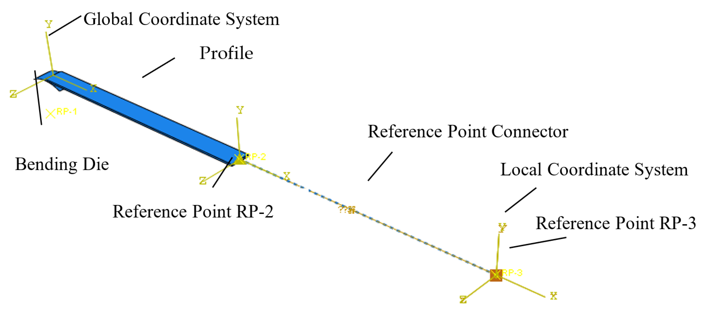
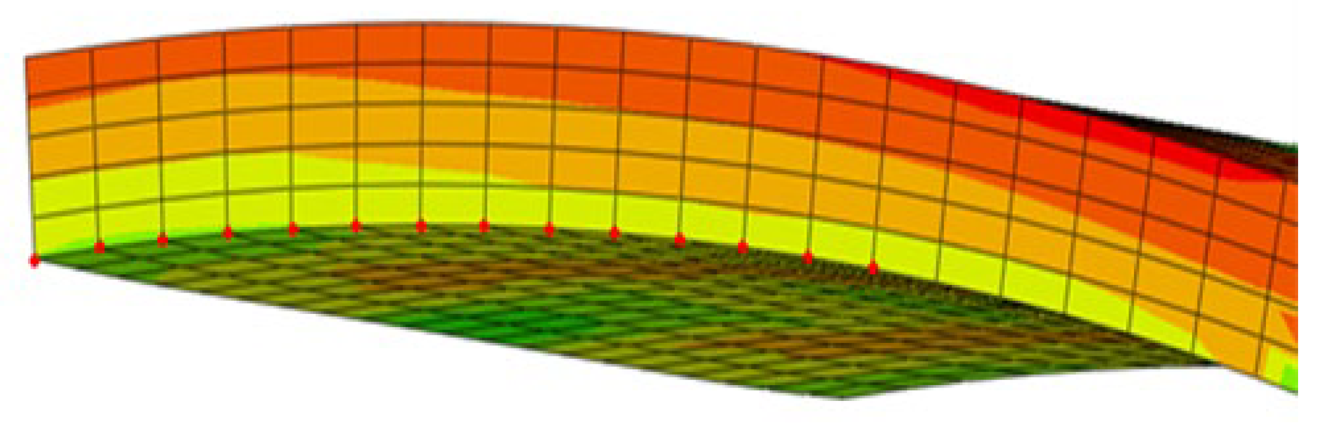
4. Numerical Simulation of Stretch-Bending

The finite element modeling of stretch-bending is carried out by using ABAQUS software, as shown in Figure 8. The stretch-bending springback law of rectangular section profile under the pre-stretching and post-bending loading path under different tension and bending radiuses was analyzed in order to compare effectively with experiment and theoretical analysis predictions.
The material and section properties of the profile are established according to Table 1 and Table 2. In order to improve the accuracy, the static implicit algorithm is adopted. The 8-node linear incompatible integration element (C3D8I) is applied to mesh the profile. The half-model is used in the finite element model to improve the calculation efficiency.
The model of stretch-bending motion mechanism used in this study referred to the model in reference [11].
The coordinate values of the nodes on the innermost layer are extracted to fit a circle as shown in Figure 9. Therefore, the residual radius after springback can be obtained to compare with the experimental and theoretical values.

5. Stretch-Bending Experiment

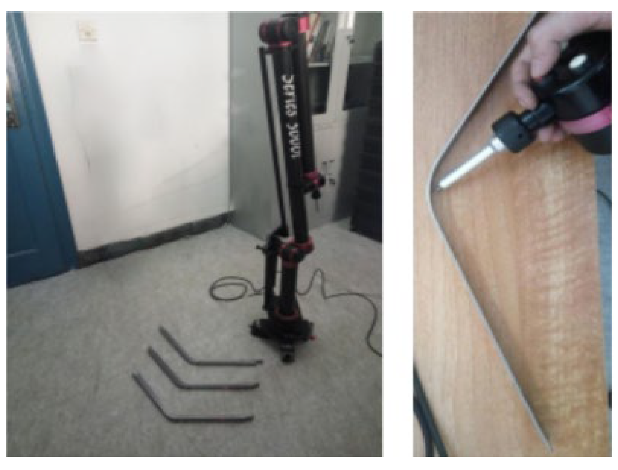
5.1. Experimental Equipment

The self-made rotary arm stretch-bending experimental machine is adopted. The main components of the stretch-bending experimental machine system include stretch-bending actuator and a hydraulic control system, as shown in Figure 10.
To verify the theoretical analysis of stretch-bending springback under a proportional kinematic hardening model, it is necessary to select the bending die with a smaller curvature radius. The die radius is 40 mm, 50 mm and 60 mm respectively. The photos of the bending die are shown in Figure 11.

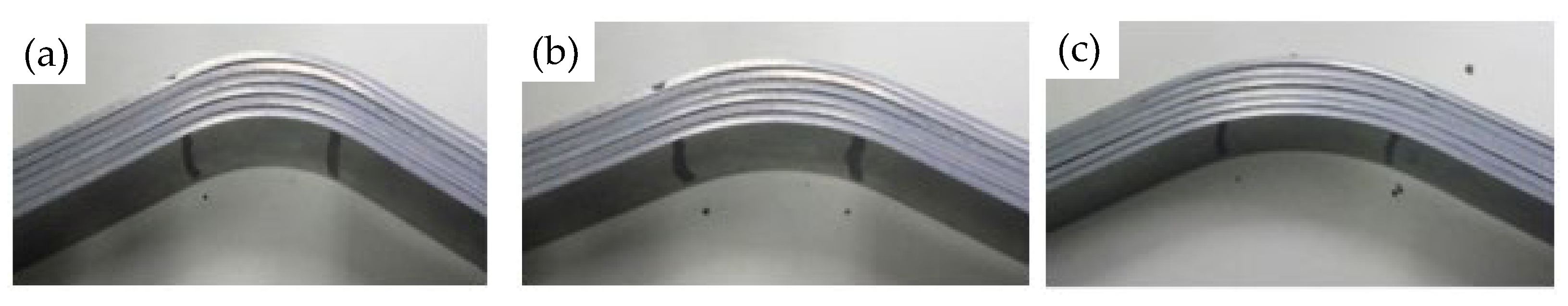
5.2. Experimental Results and Data Measurement

The photos of the specimen after stretch-bending and springback in the plastic pre-stretch and post-bending loading path is shown in Figure 12.
The Series3000iTM coordinate measuring instrument is used for the measurement of the specimens after springback of stretch-bending experiment. The measuring instrument and measurement method are shown in Figure 13.

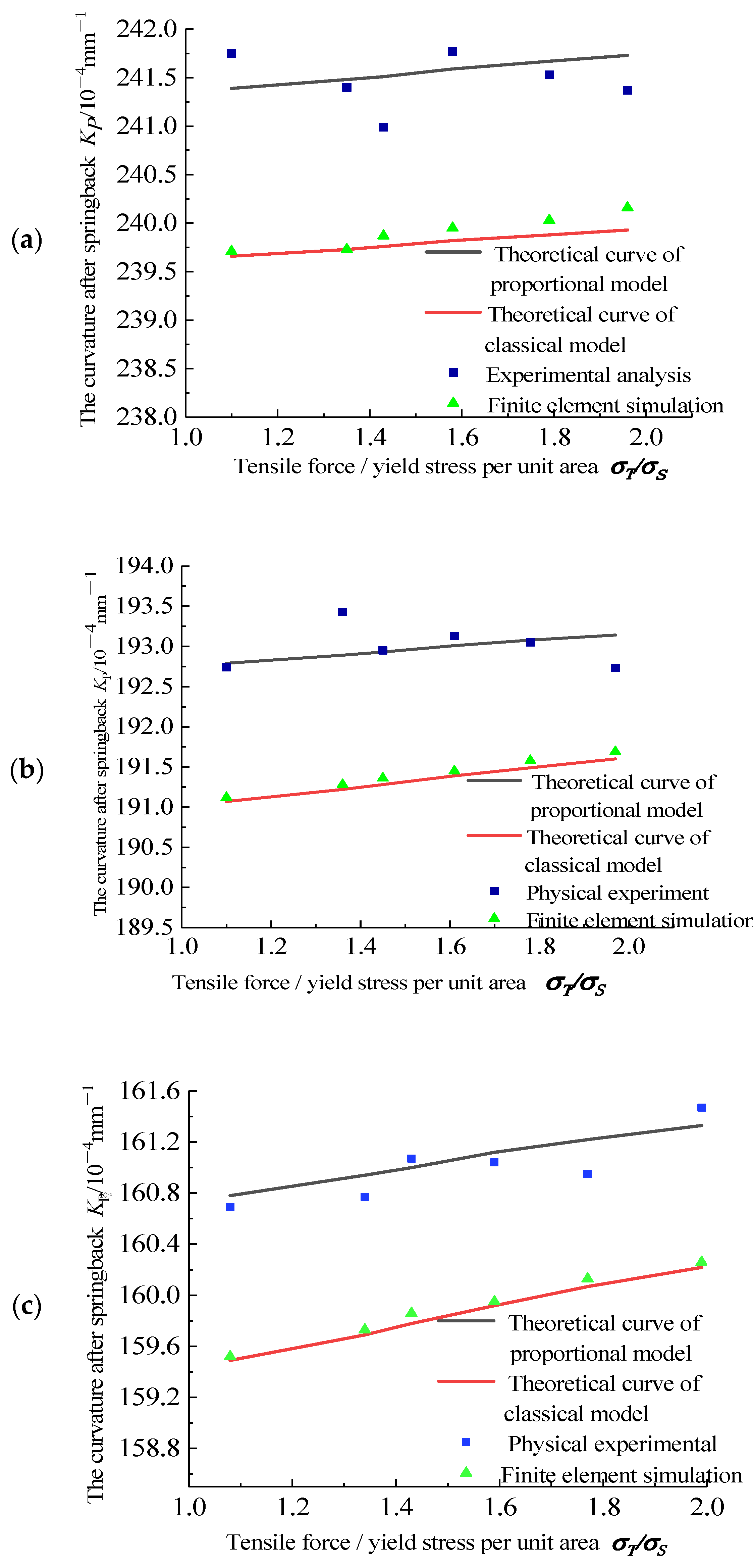
5.3. Experimental Data Analysis

The analytical springback results based on the proportional kinematic hardening model are compared with the theoretical analysis results of the classical kinematic hardening model, and the springback law of stretch-bending is obtained, as shown in Figure 14.
Under the condition of the same bending radius and the same tension, the curvature after springback of the stretch-bending experiment is closer to the theoretical analytical curvature of the proportional kinematic hardening model, and the relative deviation is less than 0.5%. The theoretical analytical curvature of the classical kinematic hardening model is generally lower the stretch-bending experiment, and the relative deviation is less than 1%.

6. Conclusions

(1)
Based on the proportional kinematic hardening model, the analytical expressions for the curvature radius of the strain neutral layer and total moment are obtained after stretch-bending loading. Then, the analytical prediction results of the springback after stretch-bending unloading are obtained based on the plane stretch-bending springback equation.
(2)
For the stretch-bending process, when the radius of the bending die does not change, the springback decreases with the increase of tensile force. When the tensile force does not change, the springback increases with the increase of the radius of the bending die.
(3)
The experimental results show that the springback analysis based on a proportional kinematic hardening model is more accurate than the results based on a classical kinematic hardening model. Compared with the experimental results of stretch-bending, the accuracy is improved by more than 0.5%.

Author Contributions

Conceptualization, R.Z. and G.Y.; Methodology, R.Z.; and G.Y.; Formal analysis, R.Z., Z.Z., J.Y., B.M. and G.Y.; Investigation, R.Z. and Z.Z.; Data curation, R.Z.; Writing—original draft, R.Z.; Visualization, R.Z.; Supervision, G.Y.; Writing—review and editing, G.Y. All authors have read and agreed to the published version of the manuscript.

Funding

This project was funded and supported by National Natural Science Foundation of China [grant number 51705449 and 52005431].

Institutional Review Board Statement

Not applicable.

Informed Consent Statement

Not applicable.

Data Availability Statement

Not applicable.

Conflicts of Interest

The authors declare no conflict of interest. The authors declare that they have no known competing financial interests or personal relationships that could have appeared to influence the work reported in this article.

References

  1. Zhao, J.; Yin, J.; Ma, R.; Ma, L.X. Springback equation of small curvature plane bending. Sci. China Technol. Sci. 2011, 54, 2386–2396. [Google Scholar] [CrossRef]
  2. Ma, J.; Welo, T. Analytical springback assessment in flexible stretch bending of complex shapes. Int. J. Mach. Tools Manuf. 2021, 160, 103653. [Google Scholar] [CrossRef]
  3. Elsharkawy, A.; El-Domiaty, A. Determination of stretch-bendability limits and springback for T-section beams. J. Mater. Process. Technol. 2001, 110, 265–276. [Google Scholar] [CrossRef]
  4. Daxin, E.; Chen, J.S.; Ding, J.; Bai, X. In-plane strain solution of stress and defects of tube bending with exponential hardening law. Mech. Based Des. Struct. Mach. 2012, 40, 257–276. [Google Scholar] [CrossRef]
  5. Daxin, E.; Chen, M.F. Numerical solution of thin-walled tube bending springback with exponential hardening law. Steel Res. Int. 2010, 81, 286–291. [Google Scholar] [CrossRef]
  6. Peng, J.W.; Li, W.D.; Wan, M.; Zhang, C.S.; Li, J.; Sun, G.A. Investigation on three-roller cylindrical bending of 2060-T8 Al-Li alloy plate for aircraft fuselage skin components. Int. J. Mater. Form. 2017, 11, 269–278. [Google Scholar] [CrossRef]
  7. Vladimirov, I.N.; Pietryga, M.P.; Reese, S. On the modelling of non-linear kinematic hardening at finite strains with application to springback—Comparison of time integration algorithms. Int. J. Numer. Methods Eng. 2007, 75, 1–28. [Google Scholar] [CrossRef]
  8. Vladimirov, I.N.; Reese, S. A finite strain isotropic/kinematic hardening model for springback simulation of sheet metals. In Proceedings of the 10th ESAFORM Conference on Material Forming, Zaragoza, Spain, 18–20 April 2007. [Google Scholar]
  9. El Megharbel, A.; El Nasser, G.A.; El Domiaty, A. Bending of tube and section made of strain-hardening materials. J. Mater. Process. Technol. 2008, 203, 372–380. [Google Scholar] [CrossRef]
  10. Nanu, N.; Brabie, G. Analytical model for prediction of springback parameters in the case of U stretch-bending process as a function of stresses distribution in the sheet thickness. Int. J. Mech. Sci. 2012, 64, 11–21. [Google Scholar] [CrossRef]
  11. Zhai, R.X.; Ding, X.H.; Yu, S.M.; Wang, C.G. Stretch bending and springback of profile in the loading method of prebending and tension. Int. J. Mech. Sci. 2018, 144, 746–764. [Google Scholar] [CrossRef]
  12. Zhao, J.; Zhai, R.X.; Qian, Z.P.; Ma, R. A study on springback of profile plane stretch-bending in the loading method of pretension and moment. Int. J. Mech. Sci. 2013, 75, 45–54. [Google Scholar] [CrossRef]
  13. Diao, K.S.; Zhou, X.B.; Jin, C.H.; Li, X.X.; Criqui, B. An experimental study on stretch-wrap bending of aluminum profile. In Proceedings of the 1st International Conference on New Forming Technology, Harbin, China, 6–9 September 2004. PEOPLES R CHINA2004. [Google Scholar]
  14. Uemori, T.; Naka, T.; Tada, N.; Yoshimura, H.; Katahira, T.; Yoshida, F. Theoretical predictions of fracture and springback for high tensile strength steel sheets under stretch bending. Procedia Eng. 2017, 207, 1594–1598. [Google Scholar] [CrossRef]
  15. Naka, T.; Hino, R.; Yoshida, F. Fracture of type 5083 aluminum sheet under warm stretch bending. engineering plasticity from macroscale to nanoscale Pts 1 and 2. Key Eng. Mater. 2003, 233, 113–118. [Google Scholar] [CrossRef]
  16. Muranaka, T.; Fujita, Y.; Otsu, M.; Haraguchi, O. Development of rubber-assisted stretch bending method for improving shape accuracy. In Proceedings of the 17th International Conference on Metal Forming, Toyohashi, Japan, 16–19 September 2018. [Google Scholar] [CrossRef]
  17. Etemadi, E.; Rahmatabadi, D.; Hosseini, S.M.; Hashemi, R. Experimental investigation of spring-back phenomenon through an L-die bending process for multilayered sheets produced by the accumulative press bonding technique. Proc. Inst. Mech. Eng. Part L J. Mater. Des. Appl. 2020, 234, 1550–1559. [Google Scholar] [CrossRef]
  18. Lamanna, G.; Caputo, F.; Grassia, L.; D’Amore, A.; Soprano, A. Numerical Simulation of a Stretch Bending Process. In Proceedings of the 8th International Conference on Fracture and Damage Mechanics, St. George, Malta, 8–10 September 2008. [Google Scholar]
  19. Bjorkhaug, L.; Welo, T. Local calibration of aluminium profiles in rotary stretch bending—Anisotropy effects. In Proceedings of the 8th International Conference on Numerical Methods in Industrial Forming Processes, Columbus, OH, USA, 13–17 June 2004. [Google Scholar]
  20. Li, Y.; Li, R.; Liang, C.; Liang, J.C.; Teng, F. Influence of the curvature of the multipoint die for flexible multipoint stretch bending on the quality of aluminum profile. Math. Probl. Eng. 2020, 2020, 5960973. [Google Scholar] [CrossRef]
  21. Huang, X.Y.; Yu, G.C.; Sun, H.L.; Zhao, J. A mechanical model of axial and circumferential bidirectional deformation for large thin-walled pipes in the process of continuous and synchronous calibration of roundness and straightness by three rollers. Int. J. Adv. Manuf. Technol. 2021, 116, 3809–3826. [Google Scholar] [CrossRef]
  22. Huang, X.Y.; Zhao, J.; Yu, G.C.; Meng, Q.D.; Mu, Z.K.; Zhai, R. X Three-roller continuous setting round process for longitudinally submerged arc welding pipes. Trans. Nonfer. Metals Soci. China 2021, 31, 1411–1426. [Google Scholar] [CrossRef]
Figure 1. Geometric diagram of any asymmetric section profile.
Symmetry 13 02389 g001
Figure 2. Schematic diagram of stretch-bending loading of profile.
Symmetry 13 02389 g002
Figure 3. Schematic diagram of a bilinear kinematic hardening model.
Symmetry 13 02389 g003
Figure 4. Mechanical model of stretch-bending loading.
Symmetry 13 02389 g004
Figure 5. Geometric diagram of rectangular section profile.
Symmetry 13 02389 g005
Figure 6. Geometrical dimension diagram of tensile–compression specimen.
Symmetry 13 02389 g006
Figure 7. Bilinear fitting of true stress–strain curve of tension−compression.
Symmetry 13 02389 g007
Figure 8. The finite element model of stretch-bender.
Symmetry 13 02389 g008
Figure 9. Result extraction after springback.
Symmetry 13 02389 g009
Figure 10. Stretch-bending experimental machine system.
Symmetry 13 02389 g010
Figure 11. Physical drawing of bending die. (a) R = 40 mm; (b) R = 50 mm; (c) R = 60 mm.
Symmetry 13 02389 g011
Figure 12. Photos of experimental specimens after springback. (a) R = 40 mm; (b) R = 50 mm; (c) R = 60 mm.
Symmetry 13 02389 g012
Figure 13. Data measurement instrument and measurement method.
Symmetry 13 02389 g013
Figure 14. Comparison figures of curvature after springback of stretch−bending. (a) R = 40 m; (b) R = 50 mm; (c) R = 60 mm.
Symmetry 13 02389 g014
Table 1. Geometric dimensions of rectangular section profiles.
B/mm h c/mm
2021
Table 2. Mechanical property parameters of materials.
Elastic Modulus E/MPaPlastic Modulus D/MPaYield Stress   σ s / MPaElastic Limit Strain   ε s
205,5981127.7178.570.00086
Table 3. Table of tensile stress value and reverse yield point during the tension-compression cycle experiment.
Number12345
Tensile stress value/MPa190210240270300
Reverse yield point/MPa−172−160−152−139−124
Table 4. Table of tensile stress and proportional coefficients during unloading in tension-compression cycle.
σ T / σ s   σ T / MPa σ r / MPa λ
1.2214−162−0.76
1.4250−146−0.58
1.6286−130−0.45
1.8321−114−0.36
2.0357−98−0.27
Publisher’s Note: MDPI stays neutral with regard to jurisdictional claims in published maps and institutional affiliations.

