Article

Solution Behavior Near Very Rough Walls under Axial Symmetry: An Exact Solution for Anisotropic Rigid/Plastic Material

by
Sergei Alexandrov
1,
Elena Lyamina
1 and
Pierre-Yves Manach
2,*
1
Ishlinsky Institute for Problems in Mechanics RAS, 119526 Moscow, Russia
2
IRDL UMR CNRS 6027, Université Bretagne Sud, Rue de Saint Maudé, 56100 Lorient, France
*
Author to whom correspondence should be addressed.
Symmetry 2021, 13(2), 184; https://doi.org/10.3390/sym13020184
Submission received: 8 January 2021 / Revised: 20 January 2021 / Accepted: 22 January 2021 / Published: 24 January 2021

Abstract

:
Rigid plastic material models are suitable for modeling metal forming processes at large strains where elastic effects are negligible. A distinguished feature of many models of this class is that the velocity field is describable by non-differentiable functions in the vicinity of certain friction surfaces. Such solution behavior causes difficulty with numerical solutions. On the other hand, it is useful for describing some material behavior near the friction surfaces. The exact asymptotic representation of singular solution behavior near the friction surface depends on constitutive equations and certain conditions at the friction surface. The present paper focuses on a particular boundary value problem for anisotropic material obeying Hill’s quadratic yield criterion under axial symmetry. This boundary value problem represents the deformation mode that appears in the vicinity of frictional interfaces in a class of problems. In this respect, the applied aspect of the boundary value problem is not essential, but the exact mathematical analysis can occur without relaxing the original system of equations and boundary conditions. We show that some strain rate and spin components follow an inverse square rule near the friction surface. An essential difference from the available analysis under plane strain conditions is that the system of equations is not hyperbolic.

1. Introduction

Most metallic materials are plastically anisotropic. The most common type of anisotropy is orthotropy. This type of anisotropy is induced, for example, by flat rolling of sheets. Rolled sheets are usually subject to subsequent sheet metal forming operations. Some of these operations induce intensive plastic deformation near frictional interfaces. An example of such an operation is the hole-flanging process [1]. Standard experimental methods are not adequate for determining material properties in regions of intensive plastic deformation [2]. In turn, new experimental methods require non-standard theoretical approaches. A prominent feature of several rigid plastic models is that some components of the strain rate tensor tend to infinity (or negative infinity) in the vicinity of certain frictional interfaces. This mathematical property of the strain rate tensor is in qualitative agreement with the distribution of strain rates that can induce a thin layer of intensive plastic deformation near the frictional interface. However, the precise asymptotic representation of solutions near frictional interfaces depends on the constitutive equations. Therefore, the corresponding asymptotic analysis should be carried out for each set of constitutive equations of interest.
The first complete investigation of the behavior of singular rigid perfectly plastic solutions near frictional interfaces was done in [3]. It was shown that the quadratic invariant of the strain rate tensor is inversely proportional to the square root of the normal distance to the friction surface. A particular case of plane strain conditions was considered separately, as it reveals some features that are different from the general case. In contrast to the general case, the plane strain equations are hyperbolic. The general analysis is valid under plane strain conditions if the frictional interface is an envelope of characteristics and is not valid if it is a regular characteristic. The extension of the main result derived in [3] to anisotropic plasticity has been restricted to plane strain conditions [4]. As in isotropic plasticity, the equations are hyperbolic, and the derivation in [4] is based on the general slip-line theory developed in [5]. The present paper adopts Hill’s quadratic yield criterion [6]. The corresponding system of equations comprising the yield criterion, its associated flow rule, and the equilibrium equations is not hyperbolic under axial symmetry. Therefore, the methodology used in [4] is not applicable in this case.
In addition to the strain rate tensor’s quadratic invariant, the spin tensor is important for anisotropic materials [7]. Under plane strain and axial symmetry conditions, only one component of this tensor does not vanish. This component’s behavior near frictional interfaces has been studied in [8], where it was shown that this component approaches infinity (or negative infinity) in the vicinity of the friction interface. The double slip and rotation model proposed in [9] was considered in this paper in conjunction with the Mohr–Coulomb yield criterion. Therefore, the equations are hyperbolic under both plane strain and axial symmetry conditions. The surface near which the spin component is singular is an envelope of characteristics.
The present paper provides an exact solution for an axisymmetric boundary value problem representing the mode of deformation in the vicinity of frictional interfaces with high friction stresses. The system of equations is not hyperbolic. The original boundary conditions include two frictional interfaces and assume that sticking occurs at each of these interfaces. It is then shown that this boundary value problem may have no solution. On the other hand, there is no physical reason for the non-existence of the solution to the boundary value problem. Therefore, the only possibility of bringing the mathematical result and physical insight into line is to assume that sliding occurs at one of the frictional interfaces. Doing so results in singular behavior of the quadratic invariant of the strain rate tensor and the only non-vanishing spin component near the frictional interface where sliding occurs.

2. Statement of the Problem

2.1. Material Model

The material is supposed to be rigid plastic (i.e., the elastic portion of the strain tensor is neglected). The boundary value problem to be solved is axisymmetric. Let θ be the azimuthal coordinate of a cylindrical coordinate system ( r , θ , z ) whose z-axis coincides with the axis of symmetry of the boundary value problem. Under axial symmetry, Hill’s quadratic yield criterion for orthotropic materials reduces to [6]
F ( σ θ θ σ y y ) 2 + G ( σ y y σ x x ) 2 + H ( σ x x σ θ θ ) 2 + 2 M σ x y 2 = 1 .
Here σ θ θ is the circumferential stress and one of the principal stresses. In addition, σ x x , σ y y and σ x y are the stress tensor components referred to the principal axes of anisotropy X and Y in a generic meridian plane; F, G, H, and M are material constants. The stress components σ x θ and σ y θ vanish. The axes X and Y are straight.
The plastic flow rule associated with the yield criterion (1) is
ξ x x = λ [ H ( σ x x σ θ θ ) + G ( σ x x σ y y ) ] ,   ξ y y = λ [ G ( σ y y σ x x ) + F ( σ y y σ θ θ ) ] , ξ θ θ = λ [ F ( σ θ θ σ y y ) + H ( σ θ θ σ x x ) ] ,   ξ x y = λ M σ x y .
Here ξ θ θ is the circumferential strain rate and one of the principal strain rates. Furthermore, ξ x x , ξ y y and ξ x y are the strain rate tensor components referred to the axes X and Y; λ is a non-negative multiplier. The equations in (2) result in the equation of incompressibility:
ξ x x + ξ y y + ξ θ θ = 0 .

2.2. Boundary Value Problem

Consider an infinite hollow cylinder of inner radius a and outer radius b (Figure 1). The axis of the cylinder coincides with the z-axis of the cylindrical coordinate system. The orientation of the X-axis relative to the r-axis is φ . It is assumed that the radial stress is constant at the outer radius of the cylinder. However, since the material is pressure-independent, the value of this constant does not change anything but the magnitude of the hydrostatic stress, which is not essential for the present paper’s objective. Therefore, it is assumed that
σ r r = 0
for r = b . Here σ r r is the radial stress. The axial and shear stresses in the cylindrical coordinate system are denoted as σ z z and σ r z , respectively. The radial velocity u is prescribed at the inner radius of the cylinder:
u = U > 0
for r = a . The axial velocity v is prescribed at both the inner and outer radii, which are friction surfaces. With no loss of generality, it is possible to assume that v vanishes at the inner radius of the cylinder. Then,
v = 0
for r = a and
v = V > 0
for r = b . The conditions (6) and (7) imply the regime of sticking at both friction surfaces.
The stress and velocity are independent of both θ and z. Therefore, the equilibrium equations in the cylindrical coordinate system reduce to
σ r r r + σ r r σ z z r = 0 ,   σ r z r + σ r z r = 0 .
The components of the strain rate tensor in this coordinate system are
ξ r r = u r ,   ξ θ θ = u r ,   ξ z z = 0 ,   ξ r θ = ξ z θ = 0 ,   ξ r z = 1 2 v r .
The transformation equations for stress components in a meridian plane give
σ x x = 1 2 ( σ r r + σ z z ) + 1 2 ( σ r r σ z z ) cos 2 φ + σ r z sin 2 φ , σ y y = 1 2 ( σ r r + σ z z ) 1 2 ( σ r r σ z z ) cos 2 φ σ r z sin 2 φ , σ x y = 1 2 ( σ r r σ z z ) sin 2 φ + σ r z cos 2 φ .
The inverse transformation is
σ r r = 1 2 ( σ x x + σ y y ) + 1 2 ( σ x x σ y y ) cos 2 φ σ x y sin 2 φ , σ z z = 1 2 ( σ x x + σ y y ) 1 2 ( σ x x σ y y ) cos 2 φ + σ x y sin 2 φ , σ r z = 1 2 ( σ x x σ y y ) sin 2 φ + σ x y cos 2 φ .
Analogously,
ξ x x = 1 2 ( ξ r r + ξ z z ) + 1 2 ( ξ r r ξ z z ) cos 2 φ + ξ r z sin 2 φ , ξ y y = 1 2 ( ξ r r + ξ z z ) 1 2 ( ξ r r ξ z z ) cos 2 φ ξ r z sin 2 φ , ξ x y = 1 2 ( ξ r r ξ z z ) sin 2 φ + ξ r z cos 2 φ .
and
ξ r r = 1 2 ( ξ x x + ξ y y ) + 1 2 ( ξ x x ξ y y ) cos 2 φ ξ x y sin 2 φ , ξ z z = 1 2 ( ξ x x + ξ y y ) 1 2 ( ξ x x ξ y y ) cos 2 φ + ξ x y sin 2 φ , ξ r z = 1 2 ( ξ x x ξ y y ) sin 2 φ + ξ x y cos 2 φ .

3. General Solution

The second equation in (8) can be immediately integrated to give
σ r z = k a r
where k is a constant of integration. The direction of the axial velocity at r = b demands that k is positive. Equation (3) is equivalent to the equation ξ r r + ξ z z + ξ θ θ = 0 or using (9) to the equation u / r + u / r = 0 . The solution of the latter equation satisfying the boundary condition (5) is
u = U a r .
It is convenient to introduce the following quantities:
σ x x σ θ θ = s 1 ,   σ θ θ σ y y = s 2 ,   σ y y σ x x = s 3 .
It is evident that
s 1 + s 2 + s 3 = 0 .
It follows from the third equation in (9) and (13) that
ξ x x + ξ y y ( ξ x x ξ y y ) cos 2 φ + 2 ξ x y sin 2 φ = 0 .
One can eliminate the strain rate components in this equation by means of (2). Then, using (16)
H s 1 ( 1 cos 2 φ ) F s 2 ( 1 + cos 2 φ ) + 2 G s 3 cos 2 φ + 2 M σ x y sin 2 φ = 0 .
The last equation in (11), (14) and (16) combine to give
σ x y cos 2 φ = k a r + s 3 2 sin 2 φ .
Using (16) one can transform the yield criterion (1) to
F s 2 2 + G s 3 2 + H s 1 2 + 2 M σ x y 2 = 1 .
It follows from (2) and (16) that
ξ x y ξ θ θ = M σ x y [ F ( σ θ θ σ y y ) + H ( σ θ θ σ x x ) ] = M σ x y ( F s 2 H s 1 ) .
Using (9) and (15) one can rewrite the last equation in (12) as
2 ξ x y = U a r 2 sin 2 φ + d v d r cos 2 φ .
Eliminating ξ x y and ξ θ θ in (22) by means of (9), (15) and (23) one gets
d v d r cos 2 φ = U a r 2 [ 2 M σ x y ( F s 2 H s 1 ) sin 2 φ ] .
One can solve Equations (17), (19) and (20) for s 2 , s 3 and σ x y to arrive at
s 2 = B s 1 N k a r ,   s 3 = C s 1 + N k a r ,   σ x y = D s 1 + T k a r .
where
A = cos 2 φ [ F + ( F + 2 G ) cos 2 φ ] M sin 2 2 φ , B = M sin 2 2 φ [ H ( H + 2 G ) cos 2 φ ] cos 2 φ A , C = cos 2 φ [ H + F + ( F H ) cos 2 φ ] A ,   D = sin 2 φ [ H + F + ( F H ) cos 2 φ ] 2 A , N = 2 M sin 2 φ A ,   T = 1 cos 2 φ ( 1 + M sin 2 2 φ A ) .
One can substitute (25) into (21) to arrive at a quadratic equation for s 1 . The solution of this equation supplies s 1 as a function of r. The right-hand side of (24) is a known function of r due to this solution and (25). Then, the solution of Equation (24) satisfying the boundary condition (6) is
v U = 2 M a cos 2 φ a r σ x y ( F s 2 H s 1 ) μ 2 d μ + tan 2 φ ( a r 1 ) .
Here, μ is a dummy variable of integration.
Using (11) one can transform the first equation in (8) to
σ r r r = s 3 cos 2 φ + σ x y sin 2 φ r .
The right-hand side of this equation is a known function of r due to the solution above. Then, the solution of Equation (28) satisfying the boundary condition (4) is
σ r r = b r ( s 3 cos 2 φ + σ x y sin 2 φ ) μ d μ .
It remains to determine k involved in the solution (14). The solution (27) and the boundary condition (7) combine to give
V U = 2 M a cos 2 φ a b σ x y ( F s 2 H s 1 ) r 2 d r + tan 2 φ ( a b 1 ) .
Since the integrand involves k, (30) is the equation for determining this parameter. A difficulty is that this equation may have no solution.

4. Analysis of the General Solution

The value of φ varies in the range 0 φ π / 4 . It is instructive and convenient to consider special cases φ = 0 and φ = π / 4 separately.

4.1. Special Case φ = 0

The physical sense of this special case is that the principal axes of anisotropy coincide with the coordinate lines of the cylindrical coordinate system. Equations (25) and (26) result in
s 2 = G s 1 ( F + G ) ,   s 3 = F s 1 ( F + G ) ,   σ x y = k a r .
Substituting (31) into (21) yields
( F G + H F + H G ) ( F + G ) s 1 2 + 2 M k 2 a 2 r 2 = 1 .
It has been shown in [6] that F G + H F + H G > 0 and F + G > 0 . Using these inequalities the solution of Equation (32) is represented as
s 1 = ± 1 2 M k 2 a 2 r 2 F + G F G + H F + H G .
It follows from (31) and (33) that
σ x y ( F s 2 H s 1 ) = k a r F + G F G + F H + G H ( 1 2 M k 2 a 2 r 2 ) 1 / 2 .
Substituting (34) into (37) at φ = 0 yields
V U = 2 k M F + G F G + F H + G H 1 b / a 1 μ 3 ( 1 2 M k 2 μ 2 ) 1 / 2 d μ .
It is seen from this equation that the solution of the boundary value problem exists only if
k 1 2 M = k m .
Moreover, since V / U > 0 , it is necessary to choose the lower sign in (35). Then, Equations (33) and (35) become
s 1 = 1 2 M k 2 a 2 r 2 F + G F G + H F + H G
and
V U = 2 k M F + G F G + F H + G H 1 b / a 1 μ 3 ( 1 2 M k 2 μ 2 ) 1 / 2 d μ ,
respectively. The integral in (38) is evaluated in terms of elementary functions. As a result,
V U = 1 k F + G F G + F H + G H ( 1 2 M k 2 a 2 b 2 1 2 M k 2 ) .
Applying l’Hospital rule to the right-hand side of this equation one can find that
lim k 0 V U = 0 .
This solution corresponds to the expansion of the cylinder without shearing. It is now assumed that the ratio V / U increases from V / U = 0 . Differentiating the right-hand side of (39) with respect to k gives
d ( V / U ) d k = F + G F G + F H + G H [ 1 k 2 ( 1 2 M k 2 1 2 M k 2 a 2 b 2 ) + 2 M ( 1 1 2 M k 2 a 2 b 2 1 2 M k 2 a 2 / b 2 ) ] .
It is convenient to rearrange this equation as
d ( V / U ) d k = 1 k 2 F + G F G + F H + G H [ 1 1 2 M k 2 1 1 2 M k 2 a 2 / b 2 ] .
It is evident that 1 2 M k 2 < 1 2 M k 2 a 2 / b 2 . Then, it is seen from (41) that the ratio V / U is a monotonically increasing function of k in the range 0 k k m . Therefore, the maximum possible value of the ratio V / U is determined from (39) at k = k m as
( V U ) m = 2 M F + G F G + F H + G H 1 a 2 b 2 .
The solution of the boundary value problem formulated in Section 2 does not exist if V / U > ( V / U ) m . This mathematical feature is common to many rigid plastic models. The solution in the range V / U > ( V / U ) m exists if the sticking boundary condition (6) is replaced with a condition of sliding. According to the maximum friction law, the regime of sliding replaces the regime of sticking if no solution under the sticking boundary condition exists [10]. In this case, the state of stress and velocity in the range V / U > ( V / U ) m is identical to that at V / U = ( V / U ) m . The latter is found using the solution above. The subsequent analysis is restricted to the case k = k m .
At φ = 0 , the axial velocity is determined from (27) and (34) as
v U = 2 a 2 M ( F + G ) F G + F H + G H a r 1 μ 2 μ 2 a 2 d μ .
Equation (29) at φ = 0 becomes
σ r r = F ( F + G ) ( F G + H F + H G ) b r 1 μ 2 μ 2 a 2 d μ .
Here s 3 has been eliminated using (31) and (33). The integrals in (43) and (44) can be evaluated in terms of elementary functions. However, it is not necessary.
Equation (24) at φ = 0 becomes
d v d r = 2 U a 2 r 2 r 2 a 2 M ( F + G ) ( F G + F H + G H ) .
Here Equation (34) has been taken into account. Equation (45) can be represented as
d v d r = O ( 1 s )
as s 0 where s = r a is the normal distance to the friction surface. It is immediate from (46) that
ξ r z = O ( 1 s )   and   | ω r z | = O ( 1 s )
as s 0 . Here ω r z is the only non-zero spin component in the cylindrical coordinate system. It is evident from (47) that both ξ r z and | ω r z | approach infinity near the frictional interface.

4.2. Special Case φ = π / 4

This case does not follow from the general case since cos 2 φ involved in (24) and (26) vanishes. Equations (17) and (21) are valid. Equations (19) and (20) become
H s 1 F s 2 + 2 M σ x y = 0   and   s 3 = 2 k a r ,
respectively. Eliminating s 3 in (17) by means of the second equation in (48) and solving the resulting equation together with the first equation in (48) for s 1 and s 2 one gives
s 1 = 2 k F a / r 2 M σ x y H + F   and   s 2 = 2 k H a / r + 2 M σ x y H + F .
Using (48) and (49) to eliminate s 1 , s 2 and s 3 in (21), one arrives at the equation:
2 M ( 2 M + H + F ) ( H + F ) σ x y 2 + 4 k 2 a 2 r 2 ( F H + G H + G F ) ( H + F ) = 1 .
Then,
σ x y = ± H + F 2 M ( 2 M + H + F ) 1 4 k 2 a 2 ( F H + G H + G F ) r 2 ( H + F ) .
It is seen from this equation that the solution of the boundary value problem exists only if
k 1 2 H + F F H + G H + G F = k m .
At φ = π / 4 , Equation (28) becomes
σ r r r = σ x y r .
Using (51) and the boundary condition (4), one can represent the solution of (53) as
σ r r = ± H + F 2 M ( 2 M + H + F ) b r 1 μ 1 4 k 2 a 2 ( F H + G H + G F ) μ 2 ( H + F ) d μ .
The integral here can be evaluated in terms of elementary functions. However, it is not necessary. The integrand in (54) is a positive valued function of μ . Therefore,
b r 1 μ 1 4 k 2 a 2 ( F H + G H + G F ) μ 2 ( H + F ) d μ
is a monotonically decreasing function of r in the range a r b . On the other hand, the radial stress should be negative at r = a . Then, it is necessary to choose the upper sign in (51) and (54) and these equations become
σ x y = H + F 2 M ( 2 M + H + F ) 1 4 k 2 a 2 ( F H + G H + G F ) r 2 ( H + F ) , σ r r = H + F 2 M ( 2 M + H + F ) r b 1 μ 1 4 k 2 a 2 ( F H + G H + G F ) μ 2 ( H + F ) d μ .
Using (2) Equation (22) is replaced with
ξ x x ξ y y ξ θ θ = H ( σ x x σ θ θ ) + 2 G ( σ x x σ y y ) + F ( σ θ θ σ y y ) F ( σ θ θ σ y y ) + H ( σ θ θ σ x x ) .
It follows from (9), (12), and (15) that
ξ x x ξ y y ξ θ θ = 2 ξ r z ξ θ θ = r v u r = r 2 v U a r .
Substituting (16) and (57) into (56), one gets
v r = U a r 2 ( H s 1 2 G s 3 + F s 2 F s 2 H s 1 ) .
Using (48), (49), and (55), it is possible to express the right hand side of this equation as a function of r. As a result,
v r = U a r 2 ( F + H ) { F H + 4 k a ( F H + G H + F G ) r 2 M + H + F 2 M ( H + F ) [ 1 4 k 2 a 2 ( F H + G H + F G ) r 2 ( H + F ) ] 1 / 2 } .
Integrating this equation and using the boundary condition (6), one arrives at
v = U a ( F + H ) a r { F H μ 2 + 4 k a ( F H + G H + F G ) μ 3 2 M + H + F 2 M ( H + F ) [ 1 4 k 2 a 2 ( F H + G H + F G ) μ 2 ( H + F ) ] 1 / 2 } d μ .
This solution and the boundary condition (7) combine to give
V U = a ( F + H ) a b { F H μ 2 + 4 k a ( F H + G H + F G ) μ 3 2 M + H + F 2 M ( H + F ) [ 1 4 k 2 a 2 ( F H + G H + F G ) μ 2 ( H + F ) ] 1 / 2 } d μ .
It is seen from this equation that the ratio V / U increases with k. Therefore, ( V / U ) m is determined from (61) at k = k m . Using (52), one finds
( V U ) m = a ( F + H ) a b { F H μ 2 + 2 a F H + G H + F G μ 3 2 M + H + F 2 M ( 1 a 2 μ 2 ) 1 / 2 } d μ .
In this case, Equation (59) becomes
v r = U a r 2 ( F + H ) [ F H + 2 a F H + G H + F G r 2 M + H + F 2 M ( 1 a 2 r 2 ) 1 / 2 ] .
It is evident from this equation that (46) and (47) are valid in the special case under consideration.

4.3. General Case

It has been shown in Section 4.1 and Section 4.2 that the solution to the boundary value problem formulated in Section 2 does not exist if k > k m . In both special cases above, F s 2 H s 1 = 0 at r = a if k = k m . This result suggests introducing the following quantity:
s 4 = F s 2 H s 1 .
Using (25) and (64), one finds
s 1 = s 4 ( F B H ) + N F ( F B H ) k a r ,   s 2 = B s 4 ( F B H ) + N H ( F B H ) k a r , s 3 = C s 4 ( F B H ) + N ( F C F B H + 1 ) k a r ,   σ x y = D s 4 ( F B H ) + ( N F D F B H + T ) k a r .
It is seen from the general structure of Equations (21) and (65) that the equation resulting from the substitution of (65) into (21) has the form
A 2 s 4 2 + A 1 s 4 k a r + A 0 ( k a r ) 2 = 1 .
Here the coefficients A 2 , A 1 , and A 0 , and are independent of both s 4 and k a / r . The substitution was made symbolically using Mathematica (version 11.3), and we found that A 1 = 0 . The coefficients A 2 and A 0 were also computed. As a result, Equation (66) becomes
A 2 s 4 2 + A 0 ( k a r ) 2 = 1 , A 0 = 4 ( G H + F G + F H ) M ( G H + F G + F H ) ( 1 + cos 4 φ ) + ( F + H ) M sin 2 2 φ , A 2 = { cos 2 φ [ F + ( F + 2 G ) cos 2 φ ] + M sin 2 2 φ } 2 [ F ( 1 + cos 2 φ ) 2 + H ( 1 cos 2 φ ) 2 + 4 G cos 2 2 φ + 2 M sin 2 2 φ ] 2 [ ( G H + F G + F H ) ( 1 + cos 4 φ ) + ( F + H ) M sin 2 2 φ ] 3 .
It is seen from this equation that no solution exists if
k > k m = 1 / A 0 .
If k = k m then s 4 = 0 at r = a and
s 4 = ± 1 A 2 1 a 2 r 2 .
It follows from (24), (64), and (69) that Equations (46) and (47) are valid in the general case.
It is straightforward to determine the distribution of the radial stress from (29) using (65) and (67).

5. Conclusions

An axisymmetric boundary value problem for material obeying Hill’s orthotropic, quadratic yield criterion has been formulated and then solved in closed form. The problem and its solution are not feasible for experimental verification. This research’s primary objective is to reveal some qualitative mathematical features of the solution that are independent of the specific boundary value problem. The boundary value problem involves two frictional interfaces. Of particular interest is the behavior of the solution near these interfaces. The original formulation of the boundary value problem requires that the regime of sticking occurs on each interface. However, this regime is not compatible with other boundary conditions at certain values of input parameters. In this case, the solution exists only if the regime of sliding is permitted at one of the frictional interfaces. It is worthy of note here that the friction law usually controls this change of friction regimes. However, in the case under consideration, the material model and other boundary conditions do.
The parameter k introduced in (14) controls the qualitative behavior of the solution. It has been shown that no solution satisfying the regime of sticking at both frictional interfaces exists if k > k m . The value of k m depends on the parameters involved in the yield criterion (1) and the orientation of the principal axes of anisotropy relative to the r-axis (Figure 1). Equations (36) and (52) show this value in two special cases, φ = 0 and φ = π / 4 , respectively, and Equation (68) does in the general case 0 < φ < π / 4 . The ratio V / U , where U is fixed, attains its maximum value at k = k m . However, there is no physical restriction on further increasing V, considered as the tool’s velocity. The boundary condition (7) is not valid, and the corresponding velocity of points of deforming material is not equal to V and is determined from the solution at k = k m .
The solution is singular at k = k m . In particular, s 4 introduced in (64) vanishes at the friction surface where the regime of sliding occurs. It is seen from Equations (24) and (58) that the derivative v / r is inversely proportional to s 4 . Therefore, the shear strain rate and spin components in the cylindrical coordinate system follow the inverse square rule shown in (47). This rule is valid if the normal strain rate in the direction orthogonal to the friction surface does not vanish at the surface (i.e., ξ r r 0 at r = a in the boundary value problem solved). The singularity above causes difficulties with numerical solutions [11,12]. Efficient numerical methods, such as the extended finite element method [13], should account for the asymptotic representation (47).
Numerous experimental results confirm that material properties generated by material forming processes at the vicinity of frictional interfaces are very different from those in bulk (for example, [14,15]). The present paper’s main result shows that the material model considered predicts high gradients of the shear strain rate and spin components near frictional interfaces, which may be connected to high gradients of material properties near such interfaces.

Author Contributions

Writing, S.A.; formal analysis, E.L.; conceptualization, P.-Y.M. All authors have read and agreed to the published version of the manuscript.

Funding

This research was made possible by grant 20-69-46070 from the Russian Science Foundation.

Data Availability Statement

Not applicable.

Conflicts of Interest

The authors declare no conflict of interest.

References

  1. Kacem, A.; Krichen, A.; Manach, P.-Y. Occurrence and effect of ironing in the hole-flanging process. J. Mater. Process. Technol. 2011, 211, 1606–1613. [Google Scholar] [CrossRef]
  2. Jaspers, S.S.; Dautzenberg, J. Material behaviour in conditions similar to metal cutting: Flow stress in the primary shear zone. J. Mater. Process. Technol. 2002, 122, 322–330. [Google Scholar] [CrossRef]
  3. Alexandrov, S.; Richmond, O. Singular plastic flow fields near surfaces of maximum friction stress. Int. J. Non-Linear Mech. 2001, 36, 1–11. [Google Scholar] [CrossRef]
  4. Alexandrov, S.; Jeng, Y.-R. Singular rigid/plastic solutions in anisotropic plasticity under plane strain conditions. Contin. Mech. Thermodyn. 2013, 25, 685–689. [Google Scholar] [CrossRef]
  5. Rice, J.R. Plane strain slip line theory for anisotropic rigid/plastic materials. J. Mech. Phys. Solids 1973, 21, 63–74. [Google Scholar] [CrossRef]
  6. Gottschalk, H.P.; Eisner, E.; Hosalkar, H.S. Medial epicondyle fractures in the pediatric population. J. Am. Acad. Orthop. Surg. 2012, 20, 223–232. [Google Scholar] [CrossRef] [PubMed]
  7. Collins, I.F.; Meguid, S.A. On the Influence of Hardening and Anisotropy on the Plane-Strain Compression of Thin Metal Strip. J. Appl. Mech. 1977, 44, 271–278. [Google Scholar] [CrossRef]
  8. Wang, Y.; Alexandrov, S.; Lyamina, E. Solution Behavior in the Vicinity of Characteristic Envelopes for the Double Slip and Rotation Model. Appl. Sci. 2020, 10, 3220. [Google Scholar] [CrossRef]
  9. Harris, D. A hyperbolic augmented elasto-plastic model for pressure-dependent yield. Acta Mech. 2014, 225, 2277–2299. [Google Scholar] [CrossRef] [Green Version]
  10. Alexandrov, S.; Richmond, O. Couette flows of rigid/plastic solids: Analytical examples of the interaction of constitutive and frictional laws. Int. J. Mech. Sci. 2001, 43, 653–665. [Google Scholar] [CrossRef]
  11. Chen, J.-S.; Pan, C.; Roque, C.M.O.L.; Wang, H.-P. A Lagrangian reproducing kernel particle method for metal forming analysis. Comput. Mech. 1998, 22, 289–307. [Google Scholar] [CrossRef]
  12. Facchinetti, M.; Mishuris, G. Analysis of the maximum friction condition for green body forming in an ANSYS environment. J. Eur. Ceram. Soc. 2016, 36, 2295–2302. [Google Scholar] [CrossRef] [Green Version]
  13. Fries, T.; Belytschko, T. The extended/generalized finite element method: An overview of the method and its applications. Int. J. Numer. Methods Eng. 2010, 84, 253–304. [Google Scholar] [CrossRef]
  14. Sasaki, T.; Morris, R.; Thompson, G.B.; Syarif, Y.; Fox, D. Formation of ultra-fine copper grains in copper-clad aluminum wire. Scr. Mater. 2010, 63, 488–491. [Google Scholar] [CrossRef]
  15. Stolyarov, A.; Polyakova, M.; Atangulova, G.; Alexandrov, S. Effect of Die Angle and Frictional Conditions on Fine Grain Layer Generation in Multipass Drawing of High Carbon Steel Wire. Metals 2020, 10, 1462. [Google Scholar] [CrossRef]
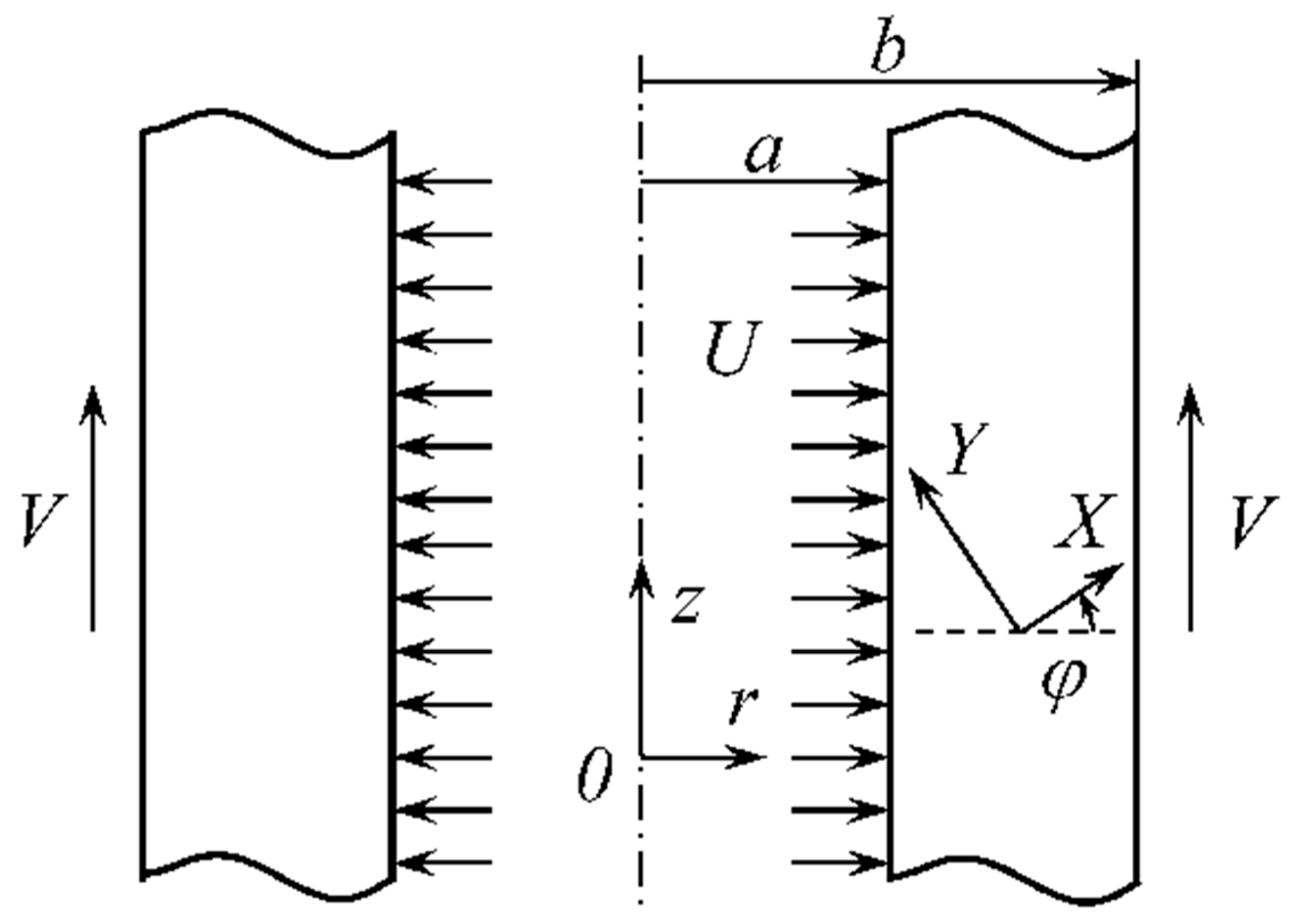
Figure 1. Illustration of the boundary value problem.
Symmetry 13 00184 g001
Publisher’s Note: MDPI stays neutral with regard to jurisdictional claims in published maps and institutional affiliations.