
Indoor Wavelet OFDM VLC-MIMO System: Performance Evaluation


Abstract
:1. Introduction
1.1. State of the Art Regarding FFT-OFDM and DWT-OFDM
1.2. Frame Work
2. System Model
2.1. The Transmitter
- 1.
- Firstly, the series input information is separated into N streams (according to N-transmitters), the positions of the LED modules are listed in Table 1. The data stream is converted from the data line to the data array, via a serial-to-parallel (S/P) converter.
- 2.
- The data is mapped to symbols by using quadrature amplitude modulation (QAM). The transmitter utilizes a 64 QAM digital modulation to map the serial bits into the OFDM symbols as N is the LED modules number and while s is the number of the parallel data stream.
- 3.
- Then, Hermitian symmetry (HS) is enforced to produce real values data.
- 4.
- 5.
- Wavelet transform for modulation is performed. As shown in Figure 1, the block named IDWT is a function in the MATLAB toolbox which utilizes Low Pass Filter (LPF) and High Pass Filter (HPF). WT utilizes filters like a vector of approximation coefficient (CA) and a vector of detail coefficients (CD). The signal is divided into sub-bands which are divided into low and high frequencies. OFDM symbol 〖Χ〗_N (i) is converted from parallel to serial. It has a vector YY that may be transposed into CA as represented in Figure 2 which is called approximated coefficients.
- A parallel-to-serial (P/S) operation is performed to obtain the time domain signal.
- Pre-SDE is implemented by normalizing all data streams to ensure that the detected N-data have the same value of SNR. The Pre-SDE concept of an optical DCO-OFDM system is based on the VLC-MIMO N-channel imaging technique. The output optical power and the modulation index for every LED are Popt and ξ, respectively. Pre-SDE is performed by using power allocation matrix A = diag (a1; a2; ⋯⋯; aN) which adjusts all electrical powers modulating data.
2.2. Channel Estimation
2.2.1. White Gaussian Noise Estimation
2.2.2. Non-Imaging LOS Channel Gain
2.2.3. Non-Imaging LOS Channel Matrix
2.3. The Receiver
- An A/D conversion is utilized to convert the analog signals to digital. The 3-dB modulation bandwidth of LED is adjusted as 50 MHz.
2.3.1. Received Wavelet-OFDM Data
2.3.2. Pre-SDE Equations
2.3.3. SNR Estimation
2.3.4. Received Data Estimation
3. Simulation Results and Discussion
3.1. Simulation Parameters
3.2. Simulation Results of Dmey Wavelet-OFDM and Discussion
4. Conclusions
Author Contributions
Funding
Institutional Review Board Statement
Informed Consent Statement
Data Availability Statement
Conflicts of Interest
References
- Vučić, J.; Langer, K. High-Speed Visible Light Communications: State-of-the-Art. In Proceedings of the Optical Fiber Communication Conference, OSA Technical Digest (Optical Society of America, 2012), Los Angeles, CA, USA, 4–8 March 2012. paper OTh3G.3. [Google Scholar]
- Zaki, A.I.; Nassar, M.; Aly, M.H.; Badawi, W.K. A generalized spatial modulation system using massive MIMO space time coding antenna grouping. Entropy 2020, 22, 1350. [Google Scholar] [CrossRef] [PubMed]
- Zaki, A.I.; Abdelgelil, M.; El-Khamy, S.E.; Badawi, W.K. MIMO Self-Heterodyne OFDM using Band Selection Technique. Entropy 2021, 23, 32. [Google Scholar] [CrossRef] [PubMed]
- Aly, R.M.; Zaki, A.; Badawi, W.K.; Aly, M.H. Time Coding OTDM MIMO System Based on Singular Value Decomposition for 5G Applications. Appl. Sci. 2019, 9, 2691. [Google Scholar] [CrossRef] [Green Version]
- Pilitha Chandran, K.; Suriyakala, C.D. Performance analysis of spatial modulation in MIMO—A survey. Int. J. Recent Adv. Sci. Technol. (IJRAST) 2015, 2, 29–35. [Google Scholar] [CrossRef]
- Le Minh, H.; O’Brien, D.; Faulkner, G.; Zeng, L.; Lee, K.; Jung, D.; Oh, Y. 80 Mbit/s visible light communications using pre-equalized white LED. In Proceedings of the European Conference on Optical Communication (ECOC), Brussels, Belgium, 21–25 September 2008. [Google Scholar]
- Mesleh, R.; Mehmood, R.; Elgala, H.; Haas, H. Indoor MIMO optical wireless communication using spatial modulation. In Proceedings of the IEEE International Conference on Communications, Cape Town, South Africa, 23 May 2010; pp. 1–5. [Google Scholar]
- Liu, Y.F.; Chang, Y.C.; Chow, C.W.; Yeh, C.H. Equalization and pre-distorted schemes for increasing data rate in in-door visible light communication system. In Proceedings of the Optical Fiber Communication Conference (OFC), Los Angeles, CA, USA, 6 March 2011. [Google Scholar]
- Chen, C.; Zhong, W.-D.; Wu, D. Indoor OFDM visible light communications employing adaptive digital pre-frequency domain equalization. In Proceedings of the Conference on Lasers and Electro-Optics (CLEO), San Jose, CA, USA, 5 June 2016. [Google Scholar]
- Zeng, L.; O’Brien, D.C.; Le Minh, H.; Faulkner, G.E.; Lee, K.; Jung, D.; Oh, Y.; Won, E.T. High data rate multiple input multiple output (MIMO) optical wireless communications using white LED lighting. IEEE J. Sel. Areas Commun. 2009, 27, 1654–1662. [Google Scholar] [CrossRef]
- Chen, C.; Zhong, W.D.; Wu, D.H. Communication coverage improvement of indoor SDM-VLC system using NHS-OFDM with a modified imaging receiver. In Proceedings of the 2016 IEEE International Conference on Communications Workshops (ICC), Kuala Lumpur, Malaysia, 23 May 2016; pp. 315–320. [Google Scholar]
- Ghassemblooy, Z.; Popoola, W.; Rajbhandari, S. Optical Wireless Communications System and Channel Modelling with Matlab; CRC Press Taylor & Francis Group: Boca Raton, FL, USA, 2013. [Google Scholar]
- Stefano, G.; Oleg, L. Recent Developments in the Standarization of Power Line Communication within the IEEE. IEEE Communications Magazine, 9 July 2008; Volume 46, 64–71. [Google Scholar]
- Linfoot, S.L.; Ibrahim, M.K.; Al-Akaidi, M.M. Orthogonal Wavelet Division Multiplxer: An Alternative to OFDM. IEEE Trans. Consum. Electron. 2007, 53, 278–284. [Google Scholar] [CrossRef]
- Mishra, R.; Mohapatra, B. Performance evaluation of OFDM system. Int. J. Eng. Adv. Technol. (IJEAT) 2012, 1, 53–56. [Google Scholar]
- Sawada, M.; Nguyen, Q.; Alhusani, M.; Sato, T. A Novel Analytical OFDM Modulation Framework using Wavelet Transform with Window Function in the Hilbert Space. In Proceedings of the Third International Conference on Computing and Network Communications (CoCoNet’19), Trivandrum, India, 18–21 December 2020; pp. 1303–1312. [Google Scholar]
- Ghanim, M.F. The effect of wavelet transform on OFDM system in modern cellular networks. Indones. J. Electr. Eng. Comput. Sci. 2019, 15, 324–327. [Google Scholar] [CrossRef]
- Asif, R.; Abd-Alhameed, R.A.; Anoh, O.O.; Dama, Y.A.S. Performance evaluation of DWT-FDM and FFT-OFDM for multicarrier communications systems using time domain zero forcing equalization. Int. J. Comput. Appl. 2012, 51, 34–38. [Google Scholar]
- Pnevmatikos, N.G.; Blachowski, B.; Hatzigeorgiou, G.D.; Swiercz, A. Wavelet analysis based damage localization in steel frames with bolted connections. Smart Struct. Syst. 2016, 18, 1189–1202. [Google Scholar] [CrossRef]
- Pnevmatikos, N.G.; Hatzigeorgiou, G.D. Damage detection of frame structures subjected to earthquake excitation using discrete wavelet analysis. Bull. Earthq. Eng. 2016, 15, 227–248. [Google Scholar] [CrossRef]
- Zayer, W.H.; Kateeb, A. OFDM based FFT compared with OFDM based wavelet transform. IOP Conf. Ser. Mater. Sci. Eng. 2019, 518, 052011. [Google Scholar] [CrossRef]
- Chen, C.; Wen-De, Z. Hybrid space-frequency domain pre-equalization for DC-biased optical orthogonal frequency division multiplexing based imaging multiple-input multiple-output visible light communication systems. Opt. Eng. 2017, 56, 036102. [Google Scholar] [CrossRef]
- Li, J.; Huang, Z.; Liu, X.; Ji, Y. Hybrid time-frequency domain equalization for LED nonlinearity mitigation in OFDM-based VLC systems. Opt. Express 2015, 23, 611–619. [Google Scholar] [CrossRef] [PubMed]
- Chan, Y.T. Wavelet Basics; Springer, Kluwer Academic Publishers: New York, NY, USA, 1995; ISBN 978-1-4615-2213-3. [Google Scholar]
- Stéphane, M. A Wavelet Tour of Signal Processing, 3rd ed.; Academic Press: Paris, France, 2008; ISBN 9780080922027. [Google Scholar]
- Komine, T.; Nakagawa, M. Fundamental analysis for visible-light communication system using LED lights. IEEE Trans. Consum. Electron. 2004, 50, 100–107. [Google Scholar] [CrossRef]
- AMoreira, A.J.; Valadas, R.T.; de Oliveira Duarte, A.M. Optical interference produced by artificial light. Wirel. Netw. 1997, 3, 131–140. [Google Scholar] [CrossRef]
- Wang, Z.; Yu, C.; Zhong, W.-D.; Chen, J.; Chen, W. Performance of a novel LED lamp arrangement to reduce SNR fluctuation for multiuser visible light communication systems. Opt. Express 2012, 20, 4564–4573. [Google Scholar] [CrossRef] [PubMed]
- Hong, Y.; Chen, J.; Yu, C. Performance improvement of the pre-coded multi-user MIMO indoor visible light communication system. In Proceedings of the International Symposium on Communication Systems, Networks & Digital Sign (CSNDSP), Manchester, UK, 23 July 2014; pp. 314–318. [Google Scholar]
- Barry, J.R.; Kahn, J.M. Link design for nondirected wireless infrared communications. Appl. Opt. 1995, 34, 3764–3776. [Google Scholar] [CrossRef] [PubMed]
- Chen, C.; Zhong, W.-D.; Wu, D. Non-Hermitian symmetry orthogonal frequency division multiplexing for multiple-input multiple output visible light communications. J. Opt. Commun. Netw. 2017, 9, 36–44. [Google Scholar] [CrossRef]


| N = 1 | (2.5, 2.5, 3) |
| N = 2 | (1.5, 2.5, 3) (3.5, 2.5, 3) |
| N = 3 | (1.5, 1.5, 3) (3.5, 1.5, 3) (2.5, 3.5, 3) |
| N = 4 | (1.5, 1.5, 3) (3.5, 1.5, 3) (1.5, 3.5, 3) (3.5, 3.5, 3) |
| Room dimensions (width × length × height) | 5 × 5 × 3 m3 |
| Number of LED modules = N | 4 |
| Number of receivers = M | 1 |
| Receiving plane height | 0.85 m |
| Half power semi angle (Ψ1/2) | 60 deg |
| LED optical output power (Popt) | 10 W |
| Modulation index (ξ) | 0.3 |
| Gain of optical filter (μ) | 1 |
| Lens gain (η) | 1 |
| Active area of PD (APD) | 19.6 mm2 |
| Photodiode responsivity (R) | 0.53 A/W |
| Background current (Ibg) | 190 μA |
| Bandwidth (B) | 50 MHz |
| QAM | 64 |
| FOV of detector | 150 deg |
| Number of carriers (QAM) | 64 |
| Number of frames = Number of symbols for each carrier (S) | 1 |
| Wavelet used (w) | ‘Dmey’ |
| Number of symbols | 1000 |
| Number of data | 64 |
| Parameters | FFT-OFDM [22] | Present Work DWT-OFDM | ||
|---|---|---|---|---|
| Common requirements | Number of subcarriers | 64 | 64 | |
| Total number OFDM symbols | 1000 | 1000 | ||
| Transmitter | Input binary data | 1 × 64,000 | 1 × 64,000 | |
| QAM data | 1 × 64,000 | 1 × 64,000 | ||
| Parallel data transmitted | 1000 × 64 | 1000 × 64 | ||
| Parallel to serial data transmitted | 1 × 64,000 | 1 × 64,000 | ||
| Normalized transmitted data | 1 × 64,000 | 1 × 64,000 | ||
| Receiver | Normalized received data | 1 × 64,000 | 1 × 64,000 | 1 × 64,000 |
| 1 × 128,000 | ||||
| Serial data received | 1 × 64,000 | 1 × 64,000 | ||
| Serial to parallel data received | 64 × 1000 | 64 × 1000 | ||
| De-QAM data | 1 × 64,000 | 1 × 64,000 | ||
| Output binary data recovery | 1 × 64,000 | 1 × 64,000 | ||
| Comparison Parameters | FFT-OFDM (Ref. [22]) | DWT-OFDM (Present Work) | |
|---|---|---|---|
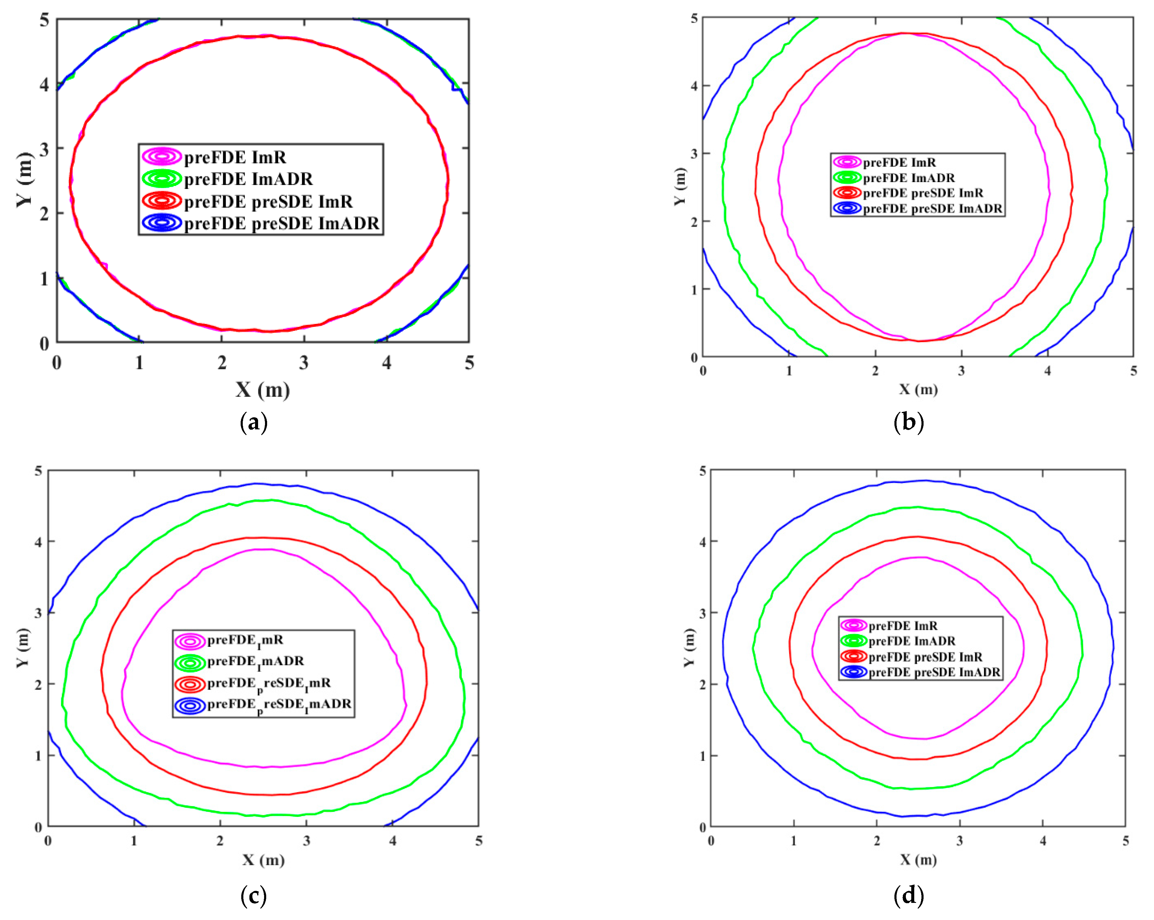
| Coverage contour | Diameter of the coverage contour employing only Pre-FDE ImADR (m) | 3.4 (52.6%) | 4 (70%) |
| Diameter of the coverage contour employing Pre-SDE after Pre-FDE ImADR (m) | 4.2 | 4.7 | |
| Diameter of the coverage contour employing only Pre-FDE ImR (m) | 2 (20%) | 2.3 (25%) | |
| Bit rate | 983.6 Mbps | 1.049 Gbps | |
| BER (along X direction) | Less than 10−5 | Less than 5 × 10⁻⁶ | |
Publisher’s Note: MDPI stays neutral with regard to jurisdictional claims in published maps and institutional affiliations. |
© 2021 by the authors. Licensee MDPI, Basel, Switzerland. This article is an open access article distributed under the terms and conditions of the Creative Commons Attribution (CC BY) license (http://creativecommons.org/licenses/by/4.0/).
Share and Cite
Badawi, W.K.; El-Hossary, M.G.; Aly, M.H. Indoor Wavelet OFDM VLC-MIMO System: Performance Evaluation. Symmetry 2021, 13, 270. https://doi.org/10.3390/sym13020270
Badawi WK, El-Hossary MG, Aly MH. Indoor Wavelet OFDM VLC-MIMO System: Performance Evaluation. Symmetry. 2021; 13(2):270. https://doi.org/10.3390/sym13020270
Chicago/Turabian StyleBadawi, Waleed K., Marwa G. El-Hossary, and Moustafa H. Aly. 2021. "Indoor Wavelet OFDM VLC-MIMO System: Performance Evaluation" Symmetry 13, no. 2: 270. https://doi.org/10.3390/sym13020270