Abstract
In order to improve hydraulic efficiency, influence of inlet angle, outlet angle, wrap angle, inlet shape and outer edge camber lines of channel-diffuser blades on the energy performance of a three-stage centrifugal pump were studied and the pressure distributions on the blade of the first-stage channel-diffuser were particularly analyzed. The result shows that the efficiency of the pump is maximal when the blade inlet angle is 12°. The pressure variation in the model with the inlet angle of 12° was small and the amplitude of fluctuation was also not large. When the outlet angle was 90°, the pressure distribution in the outlet of the blades that are symmetrically distributed along the center of the diffuser shell was significantly better than that with other outlet angles. The effect of the blade wrap angle of the channel-diffuser on the energy performance of the pump was relatively small. The internal flow in the diffuser with the diffusion inlet shapes was steady for both the convex surface and concave surface. The diffusion inlet of the channel-diffuser blade corresponded to the outlet region of the impeller blade, which reflected a good matching. The fluctuation amplitude and the distribution range of the models with a uniform transition were smaller than those with non-uniform transition. In order to verify the effectiveness of the research results, an experimental test was carried out on the pump. The results show that when the flow rate is 850 m3/h, the head of the pump is 138.67 m and the efficiency of pump is 69.48%.
1. Introduction
The diffusers in multistage pumps are mainly used to connect the impeller and next-stage impeller, and the blades of the diffusers are symmetrically distributed in the center around the outlet of the impeller. The diffusers have an effect both on the suction chamber and the discharge chamber, which takes charge of collecting the fluid outflowed from the impeller, and transports them to the inlet of next-stage impeller [1,2]. Common diffusers mainly include radial diffusers, space diffusers and channel-diffusers. The main components of the radial diffuser are positive diffusers, negative diffusers and the annular space between them. The positive diffuser is responsible for the collection of the fluid of the impeller. The negative diffuser reduces the speed of the fluid, eliminates the rotational component of the fluid, and imports the fluid into the next-stage impeller. Additionally, the annular space plays a role in the transition. The positive diffuser and negative diffuser of the space diffuser are designed into the integration. Due to its long axial dimension and short radial dimension, the hydraulic loss in the space diffuser is small. The channel-diffuser consists of several independent channels. Each independent closed channel is composed of a positive diffuser, transition section and negative diffuser. It is similar to the space diffuser in structure, but it is shorter than the space diffuser in axial direction.
At present, the design methods of the diffuser mainly include the inverse problem method, the controllable velocity moment method and the optimization method. The inverse problem design method is a kind of inverse design, which has obtained a reasonable distribution of blade load at the beginning of the design and gotten the blades meeting the design requirements after several iterations. Bonaiuti et al. [3] designed the diffuser of the injection pump with the inverse problem method and studied the velocity distribution and pressure distribution on the surface of the diffuser. Ma et al. [4] designed the diffuser of a water-jet propulsion pump by use of the axial-surface streamline, velocity moment distribution and velocity distribution based on S1/S2 stream surface theory and analyzed the effects of different velocity moments on the head and efficiency of the pump. Su et al. [5] took hydraulic efficiency as the target parameter, based on the three-dimensional inverse design method, combined with CFD (Computational Fluid Dynamics) numerical simulation, studied the best matching form of load distribution of the mixed flow pump blades and guide vanes. Cai et al. [6] used the three-dimensional controllable velocity moment method to optimize the contractive-flow guide vane model by giving the meridian surface velocity moment distribution of the guide vane. The results show that the optimized model not only improves the efficiency of the propulsion pump, but also reduces the structural size of the propulsion pump.
The optimization method selects the optimal design scheme in a variety of schemes: that is, to select a series of diffuser parameters as optimum variables, performance of pump as objective function, and finally get the optimum parameters of the diffuser with optimization technology. Kim et al. [7] used the numerical calculation and experimental design method to optimize a mixed-flow pump. They chose the key geometric parameters of the pump including the blade outlet angle of the diffuser as design variables. The optimization results show the hydraulic performance of the mixed-flow pump was significantly improved. Kim et al. [8] chose the minimal flow loss in the guide vane as the optimization objective to optimize the diffuser of a high specific-speed pump based on weighted average agent model. Finally, the efficiency of the pump at the design condition was improved. Wang et al. [9] took the AP1000 nuclear main pump as the study object, selected the outlet angle of diffuser, the angle of diffuser and the attack angle of diffuser inlet as the three factors of the orthogonal test method for numerical optimization, and the optimized pump head and efficiency were significantly improved. Duan et al. [10] took the inlet vane angle, diffusion angle, and throat area of guide vane as design variables, and optimized the guide vane of boiler water circulating pump by the orthogonal test method. In order to improve the efficiency of multi-stage centrifugal pump, Morozova et al. [11] selected the entrance diameter of the diffuser, the ratio of the input and output diameters, the radial direction diffuser angle of the channel and the number of vanes as the optimization parameters, used the automatic parametric construction method to obtain 128 computational models, and carried out calculations to obtain the best efficiency model.
Nowadays there are less studies about the channel diffuser. The axial dimension of the channel-diffuser is small and the hydraulic efficiency is high, but its design is very complex, and its manufacture is difficult. For this, in order to improve the efficiency of a the three-stage centrifugal pump, the influence of the channel-diffuser blades on the energy performance of a three-stage centrifugal pump are studied with CFD and verified by experiments.
2. Research Model and Numerical Methods
2.1. Research Model
The design flow rate of the three-stage centrifugal pump is 850 m3/h, the overall head is 131 m, and the rotation speed is 1480 r/min. The inducer is the equal-pitch inducer of which the blade number is four. The impeller is the backward inclined type of closed impeller. The key geometric parameters of the impeller and the channel-diffusers are as following. The impeller inlet diameter D1 is 260 mm, the impeller outlet diameter D2 is 420 mm, the impeller outlet width b2 is 48.2 mm, the blade wrap angle of impeller φ1 is 134°, blade number of first-stage impeller is 5, blade number of second-stage impeller and third-stage impeller are 6, the base circle diameter of channel-diffuser D3 is 425 mm, inlet width of channel-diffuser b3 is 52 mm, and the blade wrap angle of channel-diffuser φ2 = 160°, blade number of channel-diffuser is 10, which includes 5 long blades and 5 short blades. Hydraulic structures and 3D models of inducer, impeller and channel-diffuser are shown in Figure 1, Figure 2 and Figure 3. The structure and three-dimensional model of the three-stage centrifugal pump are shown in Figure 4.
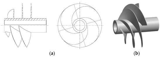
Figure 1.
Inducer: (a) hydraulic structure chart; (b) 3D model.
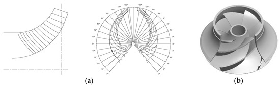
Figure 2.
Impeller: (a) hydraulic structure chart; (b) 3D model of second-stage impeller.
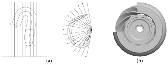
Figure 3.
Channel-diffuser casing: (a) hydraulic structure chart; (b) 3D model.
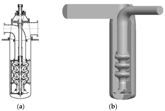
Figure 4.
The three-stage centrifugal pump: (a) structure chart; (b) 3D model of whole flow field.
2.2. Grid Generation
The grid generation of the three-stage centrifugal pump was made with GAMBIT software. Due to the complexity of the flow field structure in the pump, compared with the structured grid, the tetrahedral grid with strong adaptability can greatly reduce the workload of the calculation personnel and reduce the calculation cycle. Too few elements will affect the accuracy of numerical simulation. Too many elements will increase computational cost. Therefore, the independence of meshes should be tested. Table 1 shows comparison results of grid independence. According to the test standard the number of grid cells is considered to meet the requirements of the calculation when the difference of head in the three-stage centrifugal pump is lower than 1%. When the total mesh number is 8,569,243, the efficiency of the pump is 66.30% which is close to maximal efficiency of 66.32% under the total mesh number of 9,986,897. In order to ensure the accuracy of the calculation and saving time, we chose the total mesh number of 8,569,243 to do the next numerical simulation. The final grid is shown in Figure 5, and the number of grids for each part is shown in Table 2.

Table 1.
Comparison of grid independence.
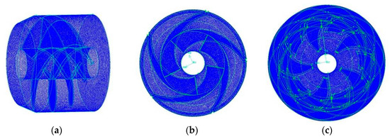
Figure 5.
Grid of flow passage components: (a) grid of inducer model; (b) grid of first-stage impeller; (c) grid of first-stage diffuser casing.
Table 2.
Mesh number of each part.
2.3. Turbulence Model and Boundary Conditions
The commercial software ANSYS-CFX was used to calculate internal flow of the three-stage centrifugal pump numerically. The calculation model includes the inlet section, the inducer, the three-stage impellers, the three-stage channel-diffusers and the outlet section. Finite volume method is chosen as the method for solution of numerical equations. It is assumed that the fluid flow in three-stage centrifugal pump is three-dimensional incompressible flow, and it follows the law of conservation of mass and momentum. The standard k-ε turbulence model and second-order upwind difference scheme are selected. The convergence precision is set to be 10−4.
In steady calculation, the boundary condition of pressure inlet is adopted, the inlet pressure is 1 atm, and the inlet fluid is assumed to be fully developed turbulence. The boundary condition of mass flow rate outlet is adopted. The no-slip wall boundary condition is adopted for all physical surfaces, that is, the component of time mean velocity and the velocity fluctuation in all directions were zero. The coupling interfaces between the inducer, the impellers and the channel-diffusers were set to be Frozen Rotor. GGI (General Grid Interface) mode was applied to grid association.
In the unsteady calculation, the speed of the impeller was 1480 rpm and the time step size was set to be 0.0001126 s. The total number of time steps was 3600, that is, the impeller rotated 10 cycles. The calculation results of the last step were selected for further analysis.
3. Numerical Calculation Results and Internal Flow Losses Analysis
The head and efficiency of the three-stage centrifugal pump at 50 m3/h, 850 m3/h and 1050 m3/h are shown in Table 3.
Table 3.
Energy performance under different flow rates.
Figure 6 shows the velocity distribution in the meridian plane of the impeller and channel-diffuser under design flow rate of 850 m3/h. As can be seen from Figure 6, the velocity distribution in the first-stage impeller is uniform and stable. However, a vortex appeared at the connection of impeller outlet and diffuser inlet. The vortex generated at the connection and was distributed along the inner streamline. Then the vortex developed towards the interior of the channel-diffuser and eventually the entire vortex formed in the inlet of the channel-diffuser, which nearly extended to the transition section of the channel-diffuser blade. There was no visible vortex on the outer streamline. There were still some vortices existing in the connection between second-stage impeller and channel-diffuser, and there were two vortices in the impeller and the channel-diffuser. The distribution of vortices in the second-stage channel-diffuser was similar to that in the first-stage channel-diffuser, but the vortices in the second-stage channel-diffuser were larger, which extended to the outer streamline. The vortex inside the impeller was generated close to the inner streamline of the impeller, which corresponded to that inside the channel-diffuser. The flow pattern in the connection of the third-stage impeller and channel-diffuser was the same as that in the previous stage. The difference is that the generation of the vortex was more serious and the area was larger. At the connection between the channel-diffuser and the next-stage impeller, the vortex and the separation flow generated on outer streamline in the inlet of the impeller.
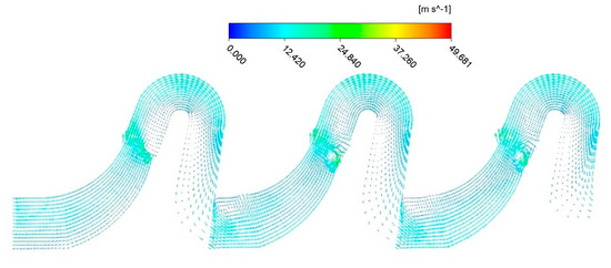
Figure 6.
Velocity distribution in the meridian plane under the design flow rate.
Table 4 gives the flow losses between each flow passage component in the three-stage centrifugal pump under design condition (850 m3/h). As can be seen from Table 4, flow loss in the three-stage impeller increases from the first-stage impeller to the final-stage impeller gradually. The flow loss in first-stage diffuser casing is minimal and the flow loss in third-stage diffuser casing is maximal. The reason is that there are some defects in the design of channel-diffuser, the diffuser could not eliminate the rotational component of the liquid effectively, which then leads to the disorder of the flow regime in the next-stage of the flow passage component and increase flow losses.
Table 4.
Flow losses of flow passage components (Unit: m).
It can be known from Table 4 that the total hydraulic loss in the three-stage impeller is 26.74 m, accounting for 36.1% of the total flow loss. The total hydraulic loss in the three-stage diffuser is 44.60 m, accounting for 60.23% of the total flow loss. The results show that the flow loss in channel-diffuser is the maximal. Therefore, it is necessary to study influence of channel-diffuser blades on energy performance of the pump to reduce the flow loss.
4. Influence of Channel-Diffuser Blades on Energy Performance of the Pump
4.1. Influence of Channel-Diffuser Blades Inlet Angle on Energy Performance of the Pump
The inlet of channel-diffuser mainly plays a role in matching upper-stage impeller to reduce the loss of hydraulic shock. Five different schemes with blade inlet angle of 10°, 12°, 15°, 17° and 20° were selected to calculate internal flow in the three-stage centrifugal pump under the flow rate of 850 m3/h numerically. The calculation results are shown in Table 5.
Table 5.
The relation between blade inlet angle of diffuser and performance.
It can be seen from Table 5 that reducing the blade inlet angle of diffuser in the effective range can improve the efficiency and head of the three-stage centrifugal pump. When the blade inlet angle of diffuser is 12°, the efficiency of the pump, whose value is 68.13%, is maximal.
In order to further analyze the flow in the channel-diffuser, the pressure distributions on the five long blade surfaces of first-stage channel-diffuser facing upstream impeller were researched. The tangent surface was located in the blade-middle of the first-stage channel-diffuser, as shown in the Figure 7.
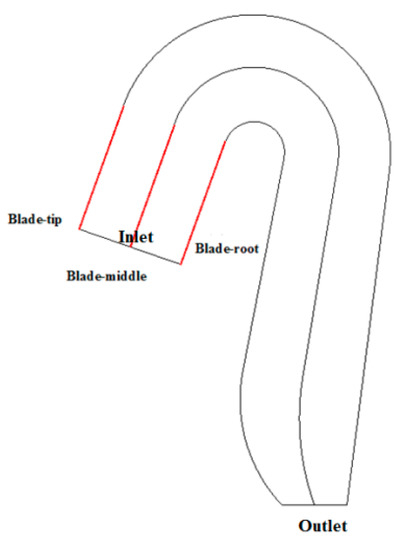
Figure 7.
Different tangent plane of five long blades in first-stage channel-diffuser.
Pressure distributions on the first-stage channel-diffuser blade surface facing upstream impeller with different inlet angles are plotted in Figure 7. At the inlet of the first-stage channel-diffuser, fluid transits from impeller to channel-diffuser. The pressure curve fluctuates for the first time because of the impact action. Then, the fluid flows in the inlet section of the channel-diffuser, and the pressure rises slightly. When the fluid passes through the transition section, the energy conversion process is unstable due to the change of the direction of the medium flow, resulting in the second pressure wave. When the fluid flows into the outlet section of the channel-diffuser, the pressure returns to be smoothly again.
It can also be seen from Figure 8 that the pressure depression in different inlet angles were similar and the range of first fluctuation was getting smaller with the increase of angle. The fluctuation in the outlet was relatively serious and the amplitude of peaks and the pressure depression of second fluctuation are relatively big when the outlet-angle is 10°. The pressure drop of second fluctuation are low when the inlet angle is 15° and 17°. When the inlet angle is 17° and 20°, the fluctuation in the inlet relatively serious and the range of fluctuation is so broad that the first fluctuation almost link to the second fluctuation. On the whole, the range of pressure variation in inlet angle of 12° is small and the amplitude of fluctuation is also not acute. The distribution of pressure on five blades with inlet angle of 12° is relatively consistent without dispersion.
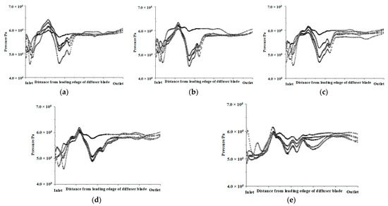
Figure 8.
Pressure distributions on the first-stage channel-diffuser blade pressure surface with different inlet angles: (a) 10°; (b) 12°; (c) 15°; (d) 17°; (e) 20°.
4.2. Influence of Channel-Diffuser Blades Outlet Angle on Energy Performance of the Pump
There is a large amount of circulation in the outlet of the channel-diffuser, which can cause additional head loss of outlet passage. The appropriate increase of the blade outlet angle of diffuser can effectively reduce the outlet circulation. That is, the outlet velocity circulation of diffuser has a great influence on the hydraulic performance of the outlet passage. Therefore, three different blade outlet angles (80°, 85°, 90°) were selected to numerically simulate internal flow in the three-stage centrifugal pump under the flow rate of 850 m3/h. The simulation results are shown in Table 6.
Table 6.
The relation between blade outlet angle of diffuser and performance.
It can be seen from Table 6 that when the blade outlet angle of diffuser is 90°, head of the three-stage centrifugal pump is maximal, whose value is 136.74 m. In other words, the loss of the outlet passage is minimal. The difference between the three schemes is small, but efficiency and head of the pump with blade outlet angle of 90° are better than that of other two schemes.
Figure 9 shows the pressure distributions on the first-stage channel-diffuser blade surface facing upstream impeller with different outlet angle. The pressure variation of outlet angle of 90° was significantly lower than that with outlet angle of 80° and 85°. Although there was an abnormal fluctuation in the transition-outlet section, the pressure distribution of the five main blades with outlet angle of 90° in the outlet was significantly better than that with the other angles. So, the outlet angle of 90° was chosen.
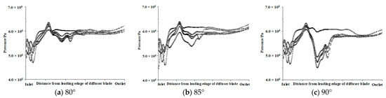
Figure 9.
Pressure distributions on the first-stage channel-diffuser blade pressure surface with different outlet angles: (a) 80°; (b) 85°; (c) 90°.
4.3. Influence of Blades Wrap Angle on Energy Performance of the Pump
The flow surface of the blade is influenced by the blade wrap angle of diffuser. The longer flow surface is conducive to the energy transformation, but increases the friction loss of liquid flow. Therefore, it is necessary to select the appropriate blade wrap angle to ensure the maximal energy conversion and the minimum friction loss. Six different blade wrap angles of 120°, 130°, 140°, 150°, 160° and 170° were selected. Simulation results under the design flow rate are shown in Table 7.
Table 7.
The relation between blade wrap angle of diffuser and performance.
According to the Table 7, it can be seen that the influence of the blade wrap angle on the performance of the pump is smaller. The head fluctuation of the pump is 3 m, and the efficiency change of the pump is less than 1%. When the blade wrap angle of diffuser is 150°, efficiency of pump, whose value is 68.67%, is maximal.
Figure 10 shows the pressure distributions on the first-stage channel-diffuser blade surface facing upstream impeller with different wrap angles. It can be seen from Figure 10 that the pressure on the first-stage channel-diffuser blade surface facing upstream impeller fluctuated in the inlet, and the first pressure drop appeared. Then the pressure increased from latter section of the inlet and the second pressure drop appeared in the transition section. Those pressure drops were different, the pressure variation in the model with wrap angle of 120° and 130° are not obvious, and the pressure variations in the model with wrap angle of 140° and 150° are severe. The pressure variation in the model with wrap angle of 160° and 170° are the most severe, which is even more than the first fluctuations and the pressure drop of the model is lowest. The range and intensity of the second fluctuations increased with the increase of the wrap angle.
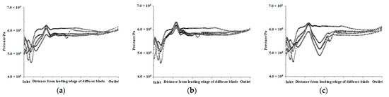
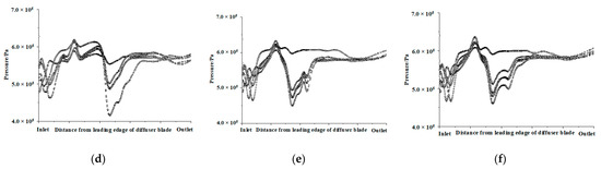
Figure 10.
Pressure distributions on the first-stage channel-diffuser blade pressure surface with different wrap angles: (a) 120°; (b) 130°; (c) 140°; (d) 150°; (e) 160°; (f) 170°.
4.4. Influence of Channel-Diffuser Blades Inlet Shape on Energy Performance of the Pump
The inlet of the channel-diffuser as the matching object was chosen to establish the matching relationship between the impeller outlet and diffuser inlet, which reduces the vortex and improves the flow regime. For this, two types of blade inlet shapes of diffusers were established (shown in Figure 11). (1) Twisted inlet of diffuser. The inlet section of the diffuser and the impeller outlet are distorted in order to reduce the interference between the impeller outlet and diffuser inlet. (2) Diffusion inlet of diffuser. The inlet section of the diffuser is parallel to the impeller outlet in order to reduce the vortex generation space.
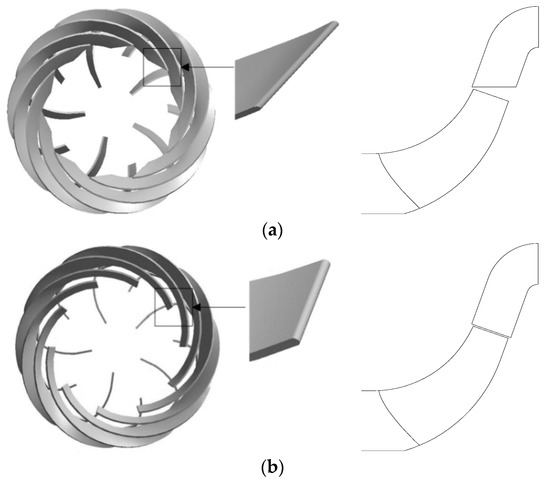
Figure 11.
Two blade inlet shapes of diffuser: (a) twisted inlet; (b) diffusion inlet.
Numerical simulation and analysis are carried out to compare the internal flow in first-stage impeller and first-stage diffuser, as shown in Figure 12. As can be seen from Figure 12, the flow of the first-stage impeller outlet is stable and uniform, which is consistent with the previous analysis of the impeller. It can also be seen from this that the design of the impeller is successful. However, the flow of first-stage channel-diffuser inlet is different. The flow of twisted inlet model which is close to the concave surface of first-stage channel-diffuser is stable. However, there are vortices in the convex surface of first-stage channel-diffuser, some of which are only formed on the inlet section of the first stage guide vane, and some of which have extended to the transition section. For the diffusion inlet model, the flow is stable on both the convex or concave surface of the first stage guide vane, and consistent with the flow at the outlet of the impeller, which reflects the good match between the impeller and the guide vane. However, there are some small vortices near the inlet of the first stage guide vane, which is caused by the gap between the impeller outlet and the inlet of the guide vane.
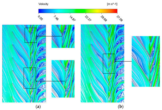
Figure 12.
Flow in first-stage impeller and first-stage channel-diffuser: (a) twisted inlet; (b) diffusion inlet.
Effects of different inlet shape on the performance of three-stage centrifugal pump under design condition (Q = 850 m3/h) are shown in Table 8. From Table 8, efficiency and head of the pump with diffusion inlet model is higher than twisted inlet model. That is to say that when the flow regime of junction area between impeller outlet and diffuser inlet is improved, the vortices in diffuser will be decreased. In the meantime, the efficiency and head of the pump will be increased.
Table 8.
The relation between blade inlet shape of diffuser and performance.
As can be seen from the above analysis, the blade inlet shape of the diffuser can effectively reduce the generation and development of vortex.
Figure 13 shows the pressure distribution on the first-stage channel-diffuser blade surface facing upstream impeller with different blades inlet shape. It can be seen from Figure 13 that the pressure distribution in different blades inlet shape is similar. Both of the pressures in two models are beginning to fluctuate from the transition section. The pressure variation in the twisted inlet appears in the forepart of the transition section, which even affected the pressure of the outlet. So there was a slight fluctuation in outlet section and the amplitude of the pressure drop was much lower than that of the pressure drop of the first fluctuation. However, the pressure variation in the model with the diffusion inlet is smaller than that of twisted inlet.
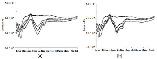
Figure 13.
Pressure distributions on the first-stage channel-diffuser blade surface with different blades inlet shape: (a) twisted inlet; (b) diffusion inlet.
4.5. Influence of Channel-Diffuser Blades Outer Edge Camber Lines on Energy Performance of the Pump
The hydraulic design of the channel-diffuser is much more difficult than the radial diffuser, mainly because it is difficult to effectively deal with the integration of the inlet section, transition section and outlet section of the channel-diffuser in the design process. Although the blade outer edge camber lines can effectively solve this problem, it is necessary to draw the best blade outer edge camber lines to ensure the three sections smoothly connected. In order to study the effect of blade outer edge camber lines on the internal fluid flow of channel-diffuser, this paper designs two kinds of blade outer edge camber lines with different trends. One is non-uniform transition. The blade outer edge camber lines of the channel-diffuser at the largest radius are parallel transition, in order to reduce the transition loss. Another is uniform transition in the blade outer edge camber lines to ensure the steady change of fluid flow. Two different types of blade outer edge camber lines are shown in Figure 14.
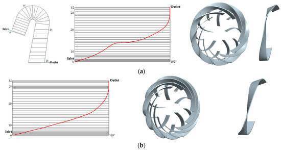
Figure 14.
Two different blade outer edge camber lines: (a) non-uniform transition; (b) uniform transition.
Figure 15 shows the internal flow in the two first-stage channel-diffusers with the different blade outer edge camber lines. It can be seen from Figure 15 that the effect of uniform transition lines is better than non-uniform transition lines in the transition of whole blade outer edge camber lines. The uniform transition outer edge camber lines can play a good role in stabilizing the fluid flow. In the transition section, there is no generation and development of vortex. However, in the model with non-uniform transition lines, the vortices appear in the initial position of the transition section, but it does not spread to the whole transition section. It can be seen that the diffuser design with the non-uniform transition outer edge camber lines has a certain effect of stabilizing fluid flow. However, the effect of stabilizing the fluid flow in the diffuser with non-uniform transition outer edge camber lines is reasonably lower compared to the diffuser with uniform transition outer edge camber lines.
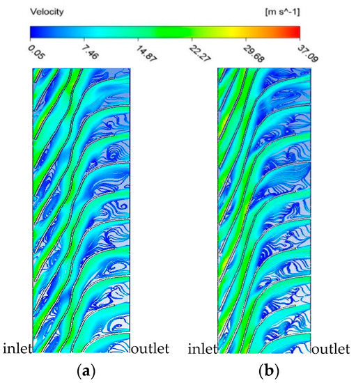
Figure 15.
Flow in first-stage channel-diffuser: (a) non-uniform transition; (b) uniform transition.
Table 9 shows the effects of two blade outer edge camber lines of channel-diffuser on performance of the three-stage centrifugal pump under the flow rate of 850 m3/h. The head and efficiency of all the pumps with the non-uniform transition are not as good as that of pumps with uniform transition, which also objectively proved the flow regime in the diffuser with uniform transition outer edge camber lines being better.
Table 9.
The relation between outer edge camber lines of diffuser blades and performance.
Figure 16 shows the pressure distributions on the first-stage channel-diffuser blade surface with respect to the chosen geometry of outer edge camber line. It can be seen that the amplitude, pressure drop, the size of fluctuation and the distribution range of model with non-uniform transition is bigger than that with uniform transition. From the transition section to the outlet, the pressure distributions with the uniform transition kept constant. The five pressure lines were consistent. There was no abrupt phenomenon on the pressure line. The pressure distribution of the five main blades at outlet was the best.
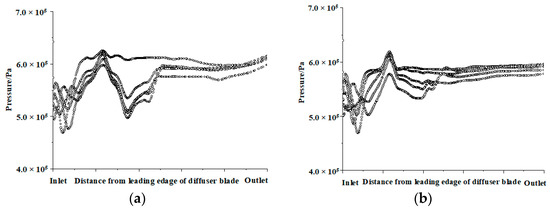
Figure 16.
Pressure distributions on the first-stage channel-diffuser blade surface with different outer edge camber lines: (a) non-uniform transition; (b) uniform transition.
4.6. Comparison of Performance between Original and Final Designs
According to the above research, steady numerical calculations with final channel-diffuser were carried out under the flow rate of 50 m3/h, 850 m3/h and 1050 m3/h. The numerical calculation results are compared with the original scheme, as shown in Table 10.
Table 10.
Comparison of energy performance.
It can be seen from Table 10, energy performances of the three-stage centrifugal pump have been improved. From Table 10, we can see that heads and efficiencies of pump with the final channel-diffuser at the three conditions (50 m3/h, 850 m3/h and 1050 m3/h) are larger than the original channel-diffuser. And efficiency of pump under the flow rate of 850 m3/h increases from 66.30% to 71.49%, which improved by 5.19 percent.
4.7. Experiment Verification
In order to further verify the effectiveness of numerical simulation results of channel-diffuser blades, the three-stage centrifugal pump (shown in Figure 17) was manufactured and its energy performance was measured.
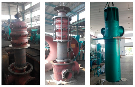
Figure 17.
The three-stage centrifugal pump.
The test bench of the three-stage centrifugal pump, which is the open cycle piping system, is shown in Figure 18. The test equipment mainly includes a triple-phase asynchronous motor, pressure sensors and a turbine flowmeter. The test methods, test accuracy and rules are strictly in accordance with the standard test criteria of P.R. China. In the test, the rotation speed is measured by the inductive sensor. The flow rate of the three-stage centrifugal pump is measured by the turbine flowmeter. The inlet pressure and outlet pressure of the pump are measured by pressure sensors. The power of the pump is measured with the electrical measurement method.
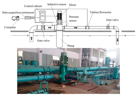
Figure 18.
Test bench of the three-stage centrifugal pump.
The calculation and test results of the energy performance of the three-stage centrifugal pump are shown in Figure 19. It can be seen from the test results on Figure 19 that when the flow rate is 0 m3/h, head of the pump is 197.08 m. When the flow rate is 850 m3/h, head of the pump is 136.67 m and efficiency of the pump is 69.48%. When the flow rate is 1050 m3/h, head of the pump is 116.85 m and efficiency of the pump is 69.89%.
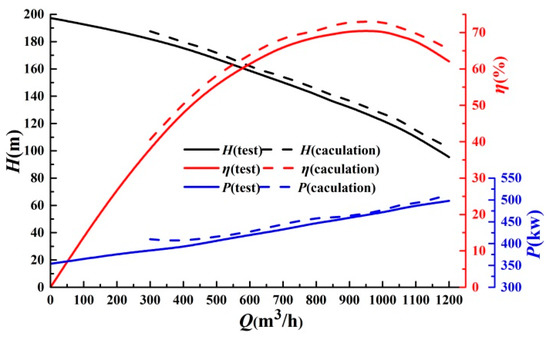
Figure 19.
The calculation and test results of energy performance.
The numerical results are in accordance with the experimental results. The calculation efficiency is 71.49% under the design flow rate, and the prediction deviation is 2.01 percentage points. The calculation head is 140.3 m, the test value is 136.67 m, and the deviation is 2.65%. The deviations between the calculation and the test results under other flow rates are all less than 5%.
5. Conclusions
The numerical calculation results of the three-stage centrifugal pump under the design condition shows that the flow loss in three-stage diffusers accounts for 60.23% of the total flow loss. Therefore, it is necessary to study the influence of channel-diffuser blades on energy performance of the pump.
Research results show that efficiency of pump is maximal when the blade inlet angle is 12°. The rang of pressure variation in the modal with inlet angle of 12° was small and the amplitude of fluctuation is also not severe. The pressure distribution of the five main blades with the outlet angle of 90° in the outlet was significantly better than that with the other angles. The effect of the blade wrap angle on the energy performance of the pump was relatively small.
Numerical results of the diffuser inlet shape show that the flow regimes of the diffuser with the diffusion inlet, whether is on the convex surface or concave surface of the channel diffuser, were stable and consistent with the impeller outlet section, which reflects a good matching. Numerical results of the diffuser blade outer edge camber lines show that the effect of uniform transition lines is better than non-uniform transition lines. The diffuser blade outer edge camber lines with uniform transition can play a good role in stabilizing the fluid flow. In the transition section, the number and area of the vortices in the diffuser with uniform transition lines are obviously small. The fluctuation amplitude and the distribution range of model with uniform transition were smaller than those with non-uniform transition.
In order to verify the effectiveness of the numerical simulation results in this paper, an experimental test was carried out on the three-stage centrifugal pump. The results show that when the flow rate Q is 850 m3/h, the head of pump is 136.67 m and the efficiency of pump is 69.48%.
Author Contributions
Conceptualization, K.W.; methodology, K.W.; software, J.H.; validation, K.W.; formal analysis, W.Z. and J.H.; investigation, W.Z.; resources, K.W.; data curation, K.W.; writing—original draft preparation, J.H.; writing—review and editing, K.W.; visualization, J.H.; supervision, J.H.; project administration, K.W.; funding acquisition, K.W. All authors have read and agreed to the published version of the manuscript.
Funding
This research was funded by the National Key Research and Development Program of China, grant number 2019YFC0312400 and 2019YFC0312403, the National Natural Science Foundation of China, grant number 51979124, the Key Research and Development Program of Zhenjiang of China, grant number GY2019026), and Priority Academic Program Development of Jiangsu Higher Education Institutions.
Conflicts of Interest
The authors declare no conflict of interest.
References
- Tan, M.G.; He, N.C.; Liu, H.L.; Wu, X.F.; Ding, J. Experimental Test on Impeller Clocking Effect in a Multistage Centrifugal Pump. Adv. Mech. Eng. 2016, 8, 1–10. [Google Scholar] [CrossRef]
- Si, Q.; Dupont, P.; Bayeul-Lainé, A.C.; Dazin, A.; Roussette, O.; Yuan, S. An Experimental Study of the Flow Field inside the Diffuser Passage of a Laboratory Centrifugal Pump. J. Fluids Eng. 2015, 137, 1–7. [Google Scholar] [CrossRef]
- Bonaiuti, D.; Zangeneh, M.; Aartojarvi, R.; Eriksson, J. Parametric Design of a Waterjet Pump by means of Inverse Design, CFD Calculations and Experimental Analyses. J. Fluids Eng. 2010, 132, 031104. [Google Scholar] [CrossRef]
- Ma, W.C.; Cao, H.; Song, S.L. Inverse Design of Water Jet Pump and Anti-cavitation Analysis. J. Jiangsu Univ. Sci. Technol. 2013, 27, 219–223. [Google Scholar]
- Su, S.H.; Liu, Z.Q. Hydraulic Performance of Guide Vane Mixed-flow Pump based on Loading Distribution. J. Drain. Irrig. Mach. Eng. 2018, 36, 1233–1239. [Google Scholar]
- Cai, Y.L.; Fan, S.M.; Chen, G.; Liang, J.; Wang, L.X. Hydrodynamic Optimization Design Method for Guide Vane of Water-Jet Contractive-Flow Pump. J. Shanghai Jiaotong Univ. 2020, 54, 28–34. [Google Scholar]
- Kim, S.; Choi, Y.S.; Lee, K.Y. Design Optimization of Mixed-flow Pump in a Fixed Meridional Shape. Int. J. Fluid Mach. Syst. 2011, 4, 14–24. [Google Scholar] [CrossRef]
- Kim, J.H.; Kim, K.Y. Optimization of Vane Diffuser in a Mix-flow Pump for High Efficiency Design. Int. J. Fluid Mach. Syst. 2011, 4, 172–178. [Google Scholar] [CrossRef]
- Wang, X.Y.; Li, Y.B.; Qi, Y.N.; Yang, C.X. Numerical Optimization on Guide Vane Hydraulic Performance of Nuclear Main Pump based on Orthogonal Test. At. Energy Sci. Technol. 2015, 12, 2181–2188. [Google Scholar]
- Duan, X.H.; Kong, F.Y.; Zhao, R.J.; Liu, Y.Y.; Tan, Q.Y. Optimization Analysis of Vaned-diffuser of Boiler Water Circulating Pump based on Orthogonal Test. J. Drain. Irrig. Mach. Eng. 2018, 36, 580–586. [Google Scholar]
- Morozova, E.; Belov, N.; Cheremushkin, V. Optimization of the Radial Channel Guide Vane of a Centrifugal Pump. IOP Conf. Ser. Mater. Sci. Eng. 2019, 589, 012008. [Google Scholar] [CrossRef]


Publisher’s Note: MDPI stays neutral with regard to jurisdictional claims in published maps and institutional affiliations. |
© 2021 by the authors. Licensee MDPI, Basel, Switzerland. This article is an open access article distributed under the terms and conditions of the Creative Commons Attribution (CC BY) license (http://creativecommons.org/licenses/by/4.0/).