Author Contributions
Conceptualization, K.W.; methodology, K.W.; software, J.H.; validation, K.W.; formal analysis, W.Z. and J.H.; investigation, W.Z.; resources, K.W.; data curation, K.W.; writing—original draft preparation, J.H.; writing—review and editing, K.W.; visualization, J.H.; supervision, J.H.; project administration, K.W.; funding acquisition, K.W. All authors have read and agreed to the published version of the manuscript.
Figure 1.
Inducer: (a) hydraulic structure chart; (b) 3D model.
Figure 1.
Inducer: (a) hydraulic structure chart; (b) 3D model.
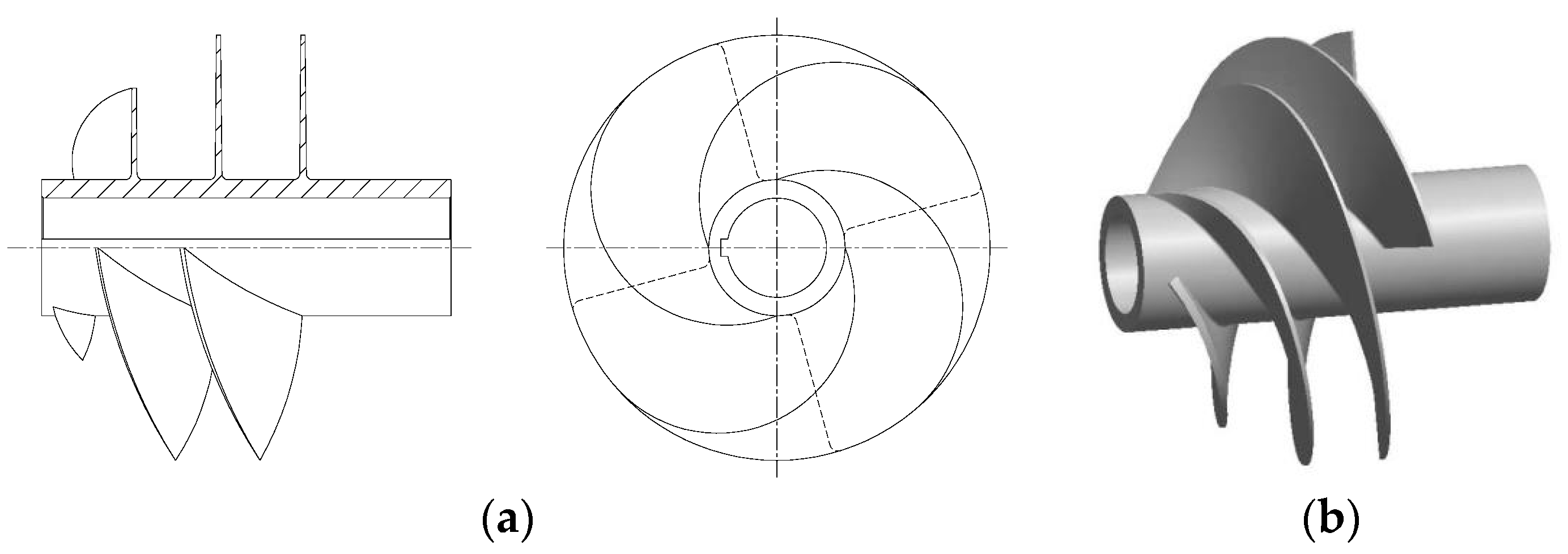
Figure 2.
Impeller: (a) hydraulic structure chart; (b) 3D model of second-stage impeller.
Figure 2.
Impeller: (a) hydraulic structure chart; (b) 3D model of second-stage impeller.
Figure 3.
Channel-diffuser casing: (a) hydraulic structure chart; (b) 3D model.
Figure 3.
Channel-diffuser casing: (a) hydraulic structure chart; (b) 3D model.
Figure 4.
The three-stage centrifugal pump: (a) structure chart; (b) 3D model of whole flow field.
Figure 4.
The three-stage centrifugal pump: (a) structure chart; (b) 3D model of whole flow field.
Figure 5.
Grid of flow passage components: (a) grid of inducer model; (b) grid of first-stage impeller; (c) grid of first-stage diffuser casing.
Figure 5.
Grid of flow passage components: (a) grid of inducer model; (b) grid of first-stage impeller; (c) grid of first-stage diffuser casing.
Figure 6.
Velocity distribution in the meridian plane under the design flow rate.
Figure 6.
Velocity distribution in the meridian plane under the design flow rate.
Figure 7.
Different tangent plane of five long blades in first-stage channel-diffuser.
Figure 7.
Different tangent plane of five long blades in first-stage channel-diffuser.
Figure 8.
Pressure distributions on the first-stage channel-diffuser blade pressure surface with different inlet angles: (a) 10°; (b) 12°; (c) 15°; (d) 17°; (e) 20°.
Figure 8.
Pressure distributions on the first-stage channel-diffuser blade pressure surface with different inlet angles: (a) 10°; (b) 12°; (c) 15°; (d) 17°; (e) 20°.
Figure 9.
Pressure distributions on the first-stage channel-diffuser blade pressure surface with different outlet angles: (a) 80°; (b) 85°; (c) 90°.
Figure 9.
Pressure distributions on the first-stage channel-diffuser blade pressure surface with different outlet angles: (a) 80°; (b) 85°; (c) 90°.
Figure 10.
Pressure distributions on the first-stage channel-diffuser blade pressure surface with different wrap angles: (a) 120°; (b) 130°; (c) 140°; (d) 150°; (e) 160°; (f) 170°.
Figure 10.
Pressure distributions on the first-stage channel-diffuser blade pressure surface with different wrap angles: (a) 120°; (b) 130°; (c) 140°; (d) 150°; (e) 160°; (f) 170°.
Figure 11.
Two blade inlet shapes of diffuser: (a) twisted inlet; (b) diffusion inlet.
Figure 11.
Two blade inlet shapes of diffuser: (a) twisted inlet; (b) diffusion inlet.
Figure 12.
Flow in first-stage impeller and first-stage channel-diffuser: (a) twisted inlet; (b) diffusion inlet.
Figure 12.
Flow in first-stage impeller and first-stage channel-diffuser: (a) twisted inlet; (b) diffusion inlet.
Figure 13.
Pressure distributions on the first-stage channel-diffuser blade surface with different blades inlet shape: (a) twisted inlet; (b) diffusion inlet.
Figure 13.
Pressure distributions on the first-stage channel-diffuser blade surface with different blades inlet shape: (a) twisted inlet; (b) diffusion inlet.
Figure 14.
Two different blade outer edge camber lines: (a) non-uniform transition; (b) uniform transition.
Figure 14.
Two different blade outer edge camber lines: (a) non-uniform transition; (b) uniform transition.
Figure 15.
Flow in first-stage channel-diffuser: (a) non-uniform transition; (b) uniform transition.
Figure 15.
Flow in first-stage channel-diffuser: (a) non-uniform transition; (b) uniform transition.
Figure 16.
Pressure distributions on the first-stage channel-diffuser blade surface with different outer edge camber lines: (a) non-uniform transition; (b) uniform transition.
Figure 16.
Pressure distributions on the first-stage channel-diffuser blade surface with different outer edge camber lines: (a) non-uniform transition; (b) uniform transition.
Figure 17.
The three-stage centrifugal pump.
Figure 17.
The three-stage centrifugal pump.
Figure 18.
Test bench of the three-stage centrifugal pump.
Figure 18.
Test bench of the three-stage centrifugal pump.
Figure 19.
The calculation and test results of energy performance.
Figure 19.
The calculation and test results of energy performance.
Table 1.
Comparison of grid independence.
Table 1.
Comparison of grid independence.
| No. | 1 | 2 | 3 | 4 | 5 |
|---|
| Mesh numbers | 4,316,569 | 6,544,729 | 8,569,243 | 9,986,897 | 11,750,827 |
| Head/m | 130.99 | 133.26 | 135.02 | 135.87 | 135.75 |
| Efficiency/% | 65.42 | 65.89 | 66.30 | 66.32 | 66.31 |
Table 2.
Mesh number of each part.
Table 2.
Mesh number of each part.
| | Inlet Section | Inducer | First-Stage Impeller | First-Stage Diffuser Casing |
|---|
| Mesh numbers | 2,422,142 | 563,153 | 513,670 | 1,150,410 |
| | Second-stage impeller | Second-stage diffuser casing | Third-stage impeller | Third-stage diffuser casing | Outlet section |
| Mesh numbers | 509,484 | 1,143,147 | 501,830 | 1,200,924 | 564,483 |
Table 3.
Energy performance under different flow rates.
Table 3.
Energy performance under different flow rates.
| Flow Rate/m3·h−1 | 50 | 850 | 1050 |
|---|
| Head/m | 182.15 | 135.02 | 101.92 |
| Efficiency/% | 4.45 | 66.30 | 68.38 |
Table 4.
Flow losses of flow passage components (Unit: m).
Table 4.
Flow losses of flow passage components (Unit: m).
| | First-Stage | Second-Stage | Third-Stage |
|---|
| Diffuser | 12.46 | 15.76 | 16.38 |
| Impeller | 3.42 | 11.10 | 12.22 |
| Inducer | 2.71 |
Table 5.
The relation between blade inlet angle of diffuser and performance.
Table 5.
The relation between blade inlet angle of diffuser and performance.
| Blade Inlet Angle/° | 10 | 12 | 15 | 17 | 20 |
|---|
| Efficiency/% | 67.07 | 68.13 | 67.22 | 66.30 | 63.50 |
| Head/m | 135.92 | 136.74 | 136.14 | 135.02 | 134.06 |
Table 6.
The relation between blade outlet angle of diffuser and performance.
Table 6.
The relation between blade outlet angle of diffuser and performance.
| Blade Outlet Angle/° | 80 | 85 | 90 |
|---|
| Efficiency/% | 67.49 | 67.75 | 68.13 |
| Head/m | 135.37 | 135.89 | 136.74 |
Table 7.
The relation between blade wrap angle of diffuser and performance.
Table 7.
The relation between blade wrap angle of diffuser and performance.
| Blade Wrap Angle/° | 120 | 130 | 140 | 150 | 160 | 170 |
|---|
| Efficiency/% | 68.09 | 68.63 | 68.28 | 68.67 | 68.13 | 68.34 |
| Head/m | 137.59 | 138.16 | 137.74 | 138.02 | 136.74 | 137.55 |
Table 8.
The relation between blade inlet shape of diffuser and performance.
Table 8.
The relation between blade inlet shape of diffuser and performance.
| Blade Inlet Shape | Twisted Inlet | Diffusion Inlet |
|---|
| Efficiency/% | 68.67 | 71.21 |
| Head/m | 138.02 | 139.00 |
Table 9.
The relation between outer edge camber lines of diffuser blades and performance.
Table 9.
The relation between outer edge camber lines of diffuser blades and performance.
| Blade Outer Edge Camber Lines | Non-Uniform Transition | Uniform Transition |
|---|
| Efficiency/% | 71.21 | 71.49 |
| Head/m | 139.00 | 140.30 |
Table 10.
Comparison of energy performance.
Table 10.
Comparison of energy performance.
| | Q = 50 m3/h | Q = 850 m3/h | Q = 1050 m3/h |
|---|
| Head/m | Efficiency/% | Head/m | Efficiency/% | Head/m | Efficiency/% |
|---|
| Original | 182.15 | 4.45 | 135.02 | 66.30 | 101.92 | 68.38 |
| Final | 187.56 | 4.93 | 140.30 | 71.49 | 120.41 | 70.28 |


