Abstract
In the construction of the new shield tunnels crossing existing tunnels, grouting rings are often installed in the existing tunnels for protection. To study the effect of grouting rings on the settlement of existing tunnels, the variations of soil properties and relevant parameters before and after the grouting are analyzed. By considering the effect of the grouting ring on the reduction of the stress and the reinforcement of the surrounding foundation soil, the stress reduction model of the heterogeneous soil layer and the model of the tunnel settlement calculation are proposed. The formula for the reduction of the stress after passing through the grouting ring is deduced. Moreover, by comprehensively taking the influences of the shield excavation and grouting ring into account, the formula for calculating the vertical displacement of the existing tunnel caused by the excavation of the new tunnel is derived. Further, the impacts of the length and the thickness of the grouting ring on the settlement of the existing tunnel are studied. The results of the theoretical calculation method proposed herein are well consistent with the data computed by the finite element model, and both follow a relatively similar change trend. According to the obtained results, installing the grouting ring on the existing tunnel can effectively reduce the tunnel settlement. Finally, the results demonstrate that increasing the length and the thickness of the grouting ring can strengthen the protection of the existing tunnel, but the effect gradually decreases.
1. Introduction
With the rapid development of the subway lines of cities, it is highly probable that a new tunnel will cross the existing subway lines in close proximity during the construction process [1,2]. Since excavation through the ground by a tunneling shield will cause the deformation and the redistribution of the stress on the surrounding soil, the existing tunnels are rather likely to be deformed due to disturbances, which will affect the safety of operation [3]. In a tunnel crossing project by a tunneling shield, it is often necessary to take certain controlling measures to protect the existing tunnels. Therefore, it is vital to study the protective measures and deformation mechanism of the existing tunnels caused by building new tunnels.
To address the above issues, a number of scholars have conducted relevant research through numerical simulation [4,5], measured data analysis [6,7], theoretical analysis [8,9], and indoor model tests [10]. There are many types of protection measures for existing tunnels. One of the effective methods is to use the grouting hole on the segment of the existing tunnels to insert a grouting pipe for grouting behind the wall of the tunnel. A large number of projects have adopted this technology and achieved good results [11,12,13]. At present, the research on the grouting technology in caves chiefly focuses on the verification of the effect of grouting rings on controlling the settlement of the existing tunnel. In practice, however, a variety of control techniques are often used to control the deformation of existing tunnels at the same time, so the effect of post-grouting on controlling the settlement of existing tunnels is superimposed on the impact of other control measures. Currently, there is no study on the effect of the grouting behind the wall of tunnels. In addition, there is no theoretical calculation method to examine the effect of the grouting rings on controlling the settlement of the existing tunnels. Therefore, it is necessary to develop a mechanical model of old and new tunnels under the influence of grouting rings and develop a theoretical method to study the effect of grouting rings on controlling the vertical deformation of existing tunnels.
In this work, Mindlin’s solution [14] is used to derive the calculation formula for the stress transfer in a heterogeneous soil layer. The stress reduction factor (Q) of the additional stress passing through the grouting ring is also calculated. A calculation model of the existing tunnel mechanics, which takes account of the influence of the reinforcement of the grouting ring, is then proposed. Moreover, the formula for calculating the vertical displacement of existing tunnels caused by the excavation of new tunnels is deduced by considering a variety of factors affected by the excavation of shield structures. Furthermore, the distribution of the vertical displacement of the existing tunnel before and after setting up the grouting rings is analyzed and compared with the results of the finite element modeling. Finally, the effects of the length (L) and thickness (t) of the grouting rings on controlling the settlement of the existing tunnel are studied.
2. Mechanical Modeling and Formula Derivation
2.1. Inadequacy of Existing Mechanical Models
First, no theoretical solution has been found for the effect of grouting rings on the displacement of the existing tunnels, and no model has been proposed for calculating the vertical displacement of the existing tunnels reinforced with grouting rings.
Second, most of researches on the calculation of the vertical displacement of existing tunnels caused by a traversing tunneling shield have not taken account of the varying degree of the reduction in the transfer of the additional stress in the inhomogeneous soil layer and the possible segmental discontinuity of the additional stress applied to the existing tunnels [15].
Third, in the process of calculating the vertical displacement of the existing tunnel, Zhou et al. [16] proposed the shear dislocation model, and Wei and Zhang [17] reported the calculation model of the coordinated deformation of shear dislocation and rigid body rotation. The accuracy of the above two models can be verified in the corresponding works [18], but both models are based on the homogeneous state of the foundation soil along the longitudinal length of the tunnel and do not take the uneven distribution of the soil stiffness along the tunnel into account.
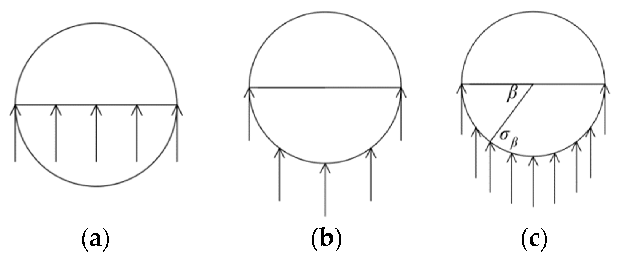
Fourth, as shown in Figure 1a, in the process of solving the additional stress applied to the existing tunnels, the current commonly used method is to ignore the influence of the tunnel radius and to replace the value of the additional stress on the surface of the tunnel segment with the value of the additional stress on the axis of the tunnel. Then, the value of the additional stress is multiplied by the diameter of the tunnel to calculate the additional stress on the tunnel. As shown in Figure 1b, Wei et al. [19] proposed a method for assessing the additional stress by averaging the additional stress values at several finite points on the surface of the tunnel segment and multiplying the resultant average by the diameter of the tunnel. For the above two methods, the additional stress on the existing tunnel is concentrated on one side of the new tunnel, i.e., a semicircle of the tunnel, rather than on a full circle. Therefore, replacing the additional stress on the axis of the tunnel with the actual force mode of the existing tunnel is slightly inaccurate. Although the accuracy of the calculation method of Wei et al. [19] is higher than that of the above method, it is still a simplified method for the calculation of the additional stress on the existing tunnel. Moreover, its accuracy depends on the number and position distribution of the calculation points on the surface of the tunnel segment. In fact, too many calculation points can adversely affect the calculation efficiency.

Figure 1.
A schematic diagram of calculating the additional stress on the existing tunnel: (a) common method, (b) method of Wei et al. [19], and (c) method of this article.
2.2. Instructions for Enhancing Existing Models
First, by referring to the research results of Guo et al. [20] on the mechanical properties of split grouted soil, this paper assumes that the variations in the main mechanical properties of the soil after grouting are reflected in the two original parameters, namely the elastic modulus (E) and the Poisson’s ratio (μ) of the soil. Other related parameters such as foundation bed coefficient (k), soil deformation modulus (E0), and soil compression modulus (Es) all vary correspondingly with the change of the elastic modulus and the Poisson’s ratio of the soil. A calculation model of the vertical displacement of the existing tunnel reinforced with the grouting rings is then established, and the calculation formula for the vertical displacement of the existing tunnel caused by the crossing tunneling shield is derived.
Second, the reduction in the additional stress will be greater when it is transferred through the grouted soil than through the general soft soil, so the final additional stress on the tunnel reinforced by the grouting is smaller than that on the unreinforced sections on both sides of the tunnel. In addition, there will be a sudden change in the additional stress on the tunnel at both ends of the grouting section, so the additional stress curve will be discontinuous. Aiming at the discontinuous multi-stage distribution mode of the additional stress on the tunnel, this paper first calculates the displacement value caused by the stress of each stage separately and then adds the displacement values together.
Third, since the elastic modulus of the reinforced grouting section and the coefficient of the foundation bed are larger than those of the surrounding soil, the foundation soil presents the characteristics of “hardness in the middle and softness at both ends”. By regarding the nonuniform distribution of the foundation soil, this work optimizes the calculation model of the coordinated deformation of shear dislocation and rigid body rotation proposed by Wei and Zhang [17] and improves the calculation formula.
Fourth, taking the example of an underpass tunnel, the vertical additional stress on the existing tunnel will be concentrated on the lower semicircular surface. As shown in Figure 1c, the vertical additional stress (σβ) on the surface of the tunnel segment has an angle of β. The actual additional stress on the existing tunnel can be measured by integrating σβ in a β range of 0–180° on the surface of the tunnel sheet. The specific formula derivation is described in Section 2.4.2.
2.3. Analysis of Principle of Grouting in Caves and Influence Mode of Grouting Rings
During the grouting in the cave, many steel flower pipes are laid in the soil behind the wall through the grouting holes on the pipe piece, and cement slurry is injected at a high pressure to form a layer of cement mortar reinforcement ring outside the pipe piece.
During the tunneling process, the shield will generate an additional stress on the surrounding soil, and the additional stress will only act on the existing tunnel after being transferred through the surrounding soil. The reinforcing grouting ring is set between the surrounding soil and the existing tunnel so that the additional stress acts on the grouting ring before affecting the existing tunnel. After the additional stress is transferred through the grouting ring, it is reduced. In the case of the displacement of the existing tunnel, the grouting ring will play an important role in fixing the tunnel and reducing the displacement.
2.3.1. Stress Reduction Calculation and Reduction Factor
Figure 2 shows the stress reduction model of the stress transfer through the grouting ring. Four points at an angle of 0, 90, 180, and 270° on the full circle grouting ring are considered to calculate the degree of reduction in the additional stress. We assume that the additional stress at the four points is indicated by , , , and , and the corresponding points of the application coordinates are (x0, y0, z0), (x1, y1, z1), (x2, y2, z2), and (x3, y3, z3). The additional stress acting on the inner surface of the grouting after the stress is transferred through the grouting ring and reduced by it is denoted by , , , and respectively, and the corresponding points of the application coordinates are (x0′, y0′, z0′), (x1′, y1′, z1′), (x2′, y2′, z2′), and (x3′, y3′, z3′). t and Rs represent the thickness of the grouting ring and the inner radius of the grouting ring, that is the radius of the existing tunnel, respectively.
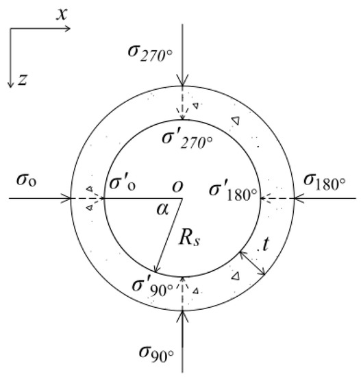
Figure 2.
Stress reduction model.
Based on Mindlin’s solution, assuming that the soil is an isotropic elastic semi-infinite body, a concentrated force acting below the ground can be used to deduce the stress component at any point in the soil. Then, the additional stress satisfies the following relationship:
where , , , , , , , and , and μ is the Poisson’s ratio of the grouting-reinforced soil.
The stress reduction factor is introduced to indicate the degree of the reduction in the stress transferred through the reinforcing grouting ring, as expressed in Equation (5):
By analogy, Qz−1, Qx−2, and Qz−3 can all be expressed separately, and Equations (1)–(4) can be reduced to the following stress reduction formulas:
where Qx−0, Qz−1, Qx−2, and Qz−3 respectively, stand for the stress reduction coefficients at the four points on the grouting ring, x and z indicate the stress direction, and 0, 1, 2, and 3 represent different research points, respectively.
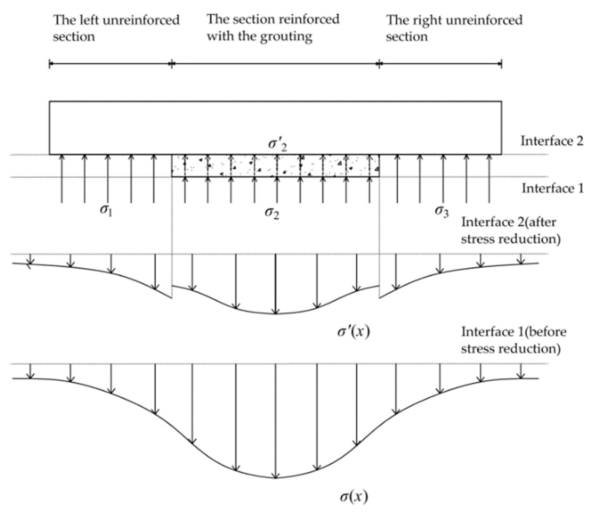
As shown in Figure 3, the reinforcement range of the grouting ring along the longitudinal direction of the tunnel is limited. The middle section of the existing tunnel is the reinforcement area of the grouting ring, and there is no protection by the reinforcing grouting ring at the far ends on both sides of the crossing center. At the height of interface 1 below the existing tunnel, the additional stress on the soil caused by the tunneling shield is not affected by the local reduction of the grouting ring, and the overall stress (σ(x)) curve shows a normal distribution along the longitudinal direction of the tunnel. When the additional stress is transferred from interface 1 into interface 2, the reduction in the additional stress will be greater when transferring through the grouted soil than through the general soft soil. The overall stress (σ′(x)) will have a greater degree of stress reduction in the section reinforced with the grouting, so a sudden change of stress appears at the edge of the section reinforced with the grouting.
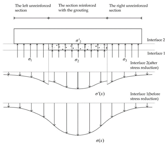
Figure 3.
Comparison of additional stress on the tunnel before and after reduction in the stress.
When solving the stress distribution along the longitudinal direction of the tunnel, it needs to be divided into three sections. The additional stress on the soil on the left and right unreinforced sections can be directly calculated by the method of Wei et al. [15]. For the section reinforced with the grouting, we can first calculate the additional stress on the soil at interface 1 and then use the stress reduction formula to determine the additional stress. The calculation is expressed through:
2.3.2. Impact of Reinforcement of Foundation Soil
Grouting the soft soil can have a certain stabilizing effect since the elastic modulus of the grouted soil is greater than that of the surrounding soft soil. Therefore, along the longitudinal direction of the existing tunnel, the section reinforced with the grouting can not only accelerate the stress reduction, but also play a vital role in reinforcing the foundation soil.
In this work, the calculation method is developed based on the model of the coordinated deformation of shear dislocation and rigid body rotation [17]. From analyzing the relevant parameters of the original model, we can infer that the main parameters affecting the properties of the foundation soil include the elastic modulus of the soil and the foundation bed coefficient. Figure 4 depicts a schematic diagram of the reinforcement effect of the grouting ring on the foundation soil. Due to the effect of the grouting reinforcement, the strength of the foundation soil in the grouting ring segment, the elastic modulus of the soil, and the foundation bed coefficient will increase. k1, E1, and μ1 represent the foundation bed coefficient, the elastic modulus of the soil, and the Poisson’s ratio of the soil respectively, in the section reinforced with the grouting. Also, k2, E2, and μ2 indicate the foundation bed coefficient, the elastic modulus of the soil, and the Poisson’s ratio of the soil respectively, in the left and right unreinforced sections. The tunnel loops in the grouting ring segment range from ring m to ring n.
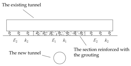
Figure 4.
Reinforcement effect of the grouting ring on the foundation soil.
2.4. Calculation of Additional Stress and Tunnel Deformation
2.4.1. Establishment of the Calculation Model
This paper regards the shield tunnel vertically under the existing tunnel as the background and considers the circular grouting of the existing tunnel to be the research object. As shown in Figure 5, the in-hole grouting of an existing tunnel will form a grouting ring close to the outer wall of the tunnel segment. The reinforcement ring is set between the new tunnel and the existing tunnel. This work assumes that the angle of the grouting ring is 180°, the thickness of the grouting ring is t, and the grouting ring is uniformly distributed along the tunnel ring and along the longitudinal direction. The length of the reinforced section of the grouting ring is L, h indicates the buried depth of the existing tunnel, and the radius of the existing tunnel is denoted by Rs. H and R represent the buried depth and the radius of the new tunnel, respectively. The influencing factors in the process of shield tunneling primarily include the additional thrust (q) of the cutter head, the side friction resistance (f) of the shield shell, the additional grouting pressure (p) of the shield tail, and the soil loss.
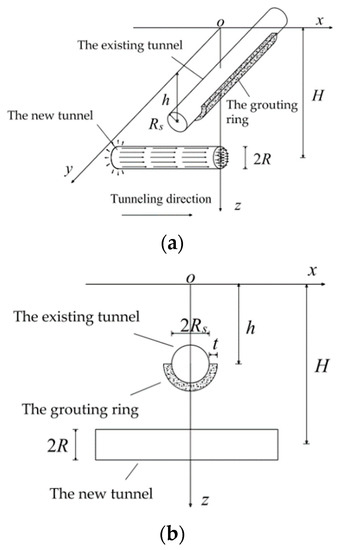
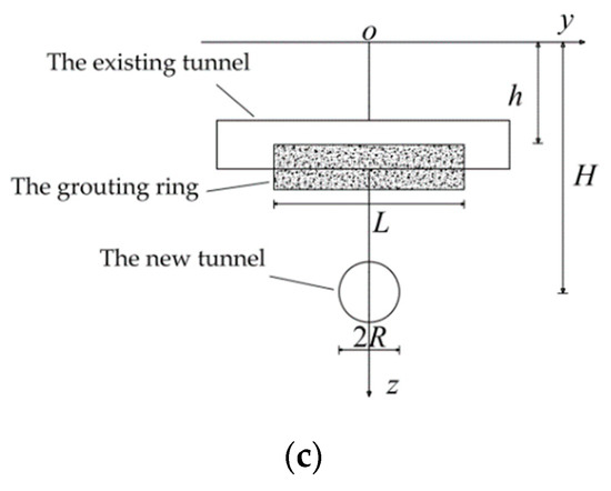
Figure 5.
Calculation model diagram: (a) three-dimensional diagram, (b) front view, and (c) side view.
2.4.2. Calculation of Additional Stress on Existing Tunnels
We refer to the method of Wei et al. [15] to calculate the additional stress on the soil caused by tunnel excavation. The additional stress on the section reinforced with the grouting needs to be derived from the additional stress on the outer surface of the grouting ring and then converted to the additional stress on the tunnel segment through the stress reduction formula. The additional stress on the left and right unreinforced sections can be obtained directly.
and represent the additional stress on the surface of the unreinforced segment on the left and on the right respectively, and indicates the additional stress on the outer surface of the grouting ring in the reinforced segment.
As shown in Figure 6a, when solving the additional stress on the reinforced section of the non-grouting ring, we assume that the vertical additional stress acting on the lower semicircle of the segment is σβ, and the angle between the connecting point of action and the horizontal radius is β (0 ≤ β ≤ 180°); then, the coordinates of the calculated points should satisfy:
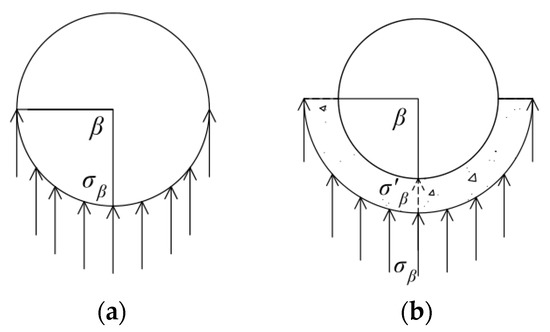
Figure 6.
A schematic diagram of solving additional stress in different sections: (a) the unreinforced sections, and (b) the section reinforced with the grouting.
Additional stress on the left (P1) and right (P3) unreinforced sections are calculated by integration as follows:
As shown in Figure 6a, when solving the additional stress on the reinforced section of the grouting ring, we assume that the vertical additional stress acting on the lower semicircle of the segment is σβ, and the angle is β (0 ≤ β ≤ 180°); then, the coordinates of the calculated points should fulfill:
Additional stress on the outer surface of the grouting ring (P2) can be calculated by integration, as follows:
Equation (14) is multiplied by the stress reduction factor to calculate the additional stress directly acting on the outer wall of the tunnel segment by the grouting section, i.e., , as follows:
2.4.3. Calculation of Vertical Displacement of the Existing Tunnel
The synergistic deformation model of the shear misalignment and rigid body rotation [17] is based on the energy-variant method in the process of calculating the displacement of the tunnel. It is believed that the function of the additional stress on the existing tunnel is used to overcome the stratigraphic resistance, inter-ring shear, and inter-ring tension [17]. In a matrix form, the effect of the additional stress on the existing tunnel can be defined as [17]:
where is the interaction effect between the segment rings, represents the effect of soil resistance, and is the effect of the additional stress on the tunnel.
Due to the uniform distribution of the stiffness of the existing tunnel along the longitudinal direction, the formulae for calculating the inter-ring shear force, the inter-ring tension, and the inter-ring interaction effect of the tube sheet are the same as those presented in the original paper [17]; thus, they are not repeated herein. The work done by the additional stress needs to be divided into three sections for separate calculations. Here, the work done by overcoming the formation resistance and the work done by the additional stress are discussed. To this end, the soil stiffness matrix () and are expanded as follows:
where N is the number of ring segments affected on one side of the existing tunnel, Dt stands for the ring width of the segment, D represents the diameter of the existing tunnel, w(y) and are the displacement along the tunnel and the additional stress respectively, is the matrix element, and .
According to the introduction in Section 2.3.2 and Section 2.4.2, the expansion forms of and are adjusted, and the adjusted soil stiffness matrix () and the adjusted matrix of the effect of the additional stress () are expressed as:
Further, the undetermined coefficient matrix (AT) can be defined as:
The vertical displacement of the existing tunnel (ω(y)) is given by:
Finally, all the above related calculations are programmed and calculated by MATLAB, MathWorks.
3. Example Analysis and Reliability Verification
3.1. Related Parameters of Examples
In order to verify the reliability of the developed model, this paper regards a new tunnel running vertically through the existing tunnel as a study case, in which the lower part of the existing tunnel is protected by a grouting ring. The relevant parameters required for the calculation of the example are as follows: H = 20 m, h = 10 m, Rs = R = 3.1 m, p = 120 kPa, f = 110 kPa, q = 45 kPa, N = 250, Dt = 1.5 m, t = 1.5 m, L = 30 m, m = −10, n = 10, E1 = 32 MPa, E2 = 10 MPa, μ1 = 0.27, and μ2 = 0.35 [20]. The maximum rate of the soil loss of the tunnel excavation (η) is 1.5%, and the distance from the moving focus of the soil to the center of the tunnel (d) is 2.48 m. The influence range of the shield tail grouting (mt) is equal to 7.5 m, and the proportional coefficient of the effect of the rigid body rotation (j) is 0.3. The equivalent bending stiffness of the tunnel (EtIt) is equal to 1.1 × 10⁸ kN·m2, and the shear stiffness between the tunnel rings (ks) and the tensile stiffness between the tunnel rings (kt) are 7.45 × 10⁵ and 1.94 × 10⁶ kN/m, respectively [17].
3.2. Reliability Verification
3.2.1. Three-Dimensional Finite Element Modeling
The 3D finite element model is built using MIDAS GTS NX software in combination with the working conditions of the calculation example. In order to verify the reliability of the calculation method proposed in this work, the parameters involved in the finite element model are the same as those used in the theoretical calculation examples. Figure 7 and Figure 8 illustrate the meshing diagram and a schematic of the model of the traversing tunneling shield, respectively. The tunnel model and the soil are both considered to be solid units, and the length, width, and height of the calculation model are 66, 66, and 66 m, respectively.
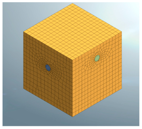
Figure 7.
Model meshing.
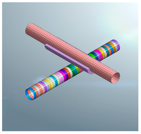
Figure 8.
A schematic of the model of the traversing tunneling shield.
The Mohr-Coulomb constitutive model is used to simulate the soil layer, and the material parameters are listed in Table 1. The steps of the finite element modeling are as follows:

Table 1.
Physical and mechanical parameters of the materials.
- Activate all the solid meshes, excavate the existing tunnel soil, generate the segments of the existing tunnel, and clear the displacement.
- Modify the properties of the grouting ring element and clear the displacement.
- Activate the thrust and shield force of the first ring and inactivate the soil of the first ring tunnel.
- Construct the first ring segment and inactivate the shield shell force of the first ring.
- Activate the thrust force and shield shell force of the second ring, inactivate the thrust force and blunt shell force of the first ring, and inactivate the soil of the second ring tunnel.
- Repeat and perform the above excavation and segment construction in sequence.
3.2.2. Comparison of Results
The shield excavation face was set at x = 50 m. Figure 9 shows the cloud diagram of the tunnel displacement computed by the finite element model before and after setting up the grouting ring.
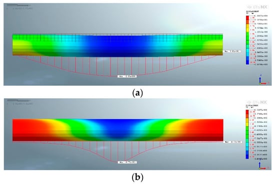
Figure 9.
Nephogram of the tunnel displacement computed by the numerical modeling of the longitudinal deformation of the existing tunnel (unit: mm): (a) no grouting ring is used, and (b) a grouting ring is set up.
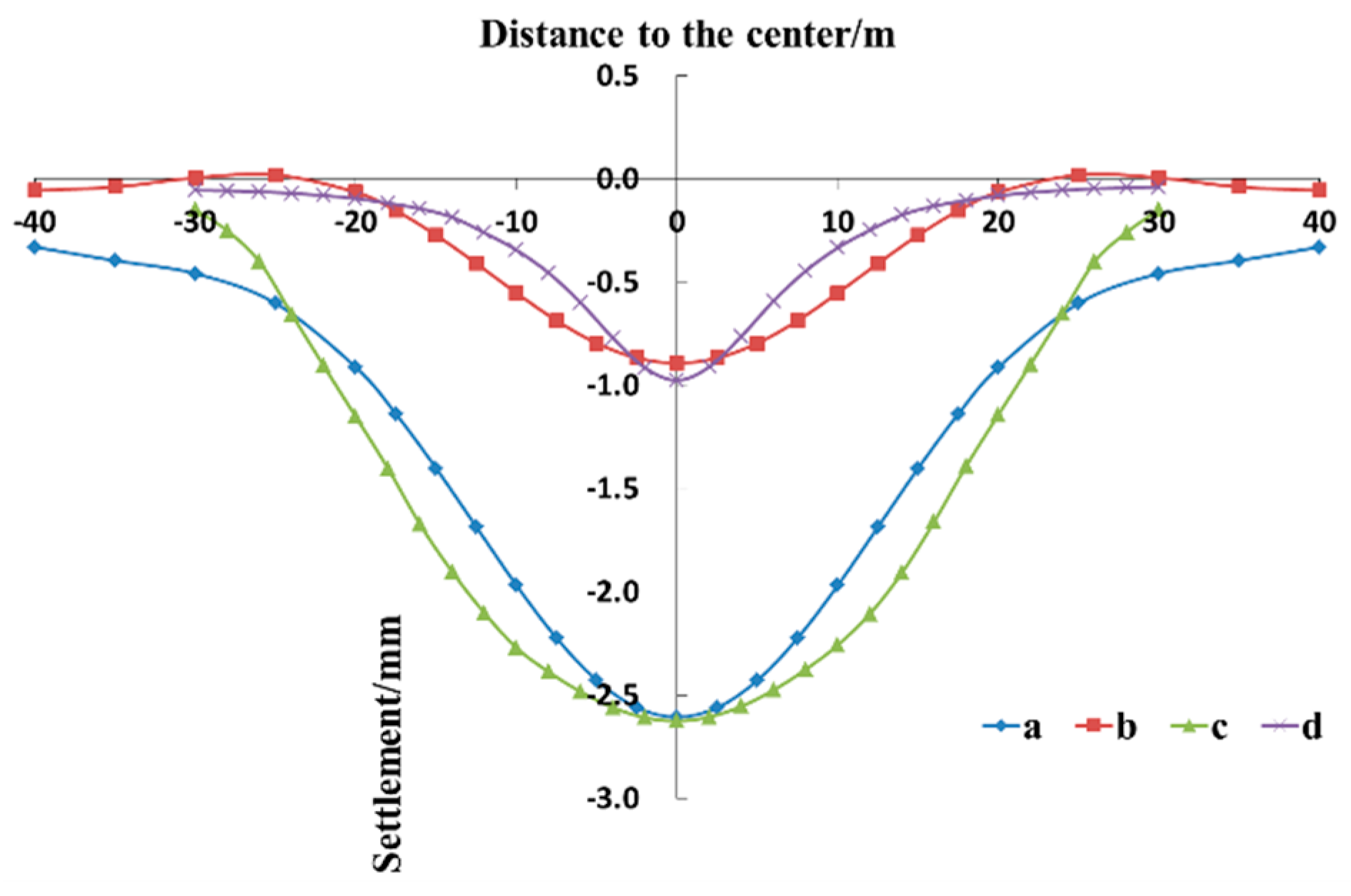
Figure 10 compares the settlement of the existing tunnel computed by the finite element model and the calculation method proposed in this paper, with or without setting up the grouting ring. According to the figure, first, when the grouting ring is not set up, the proposed calculation method is relatively consistent with the finite element model, and both follow an almost similar change trend. The maximum settlement of the existing tunnel occurs in the center of the tunnel. Also, the maximum settlement calculated by the proposed method is 2.61 mm, while the maximum settlement computed by the finite element model is 2.63 mm, which indicates a difference of only 0.02 mm; therefore, the proposed method fulfills the accuracy requirements. Second, when the grouting ring is installed, the settlement curve obtained from the theoretical calculation method is flatter than the one computed by the finite element model; however, the overall deformation trend is the same. The maximum settlement in the center of the existing tunnel calculated by the proposed method and by the finite element model is 0.89 and 0.98 mm respectively, which indicates a relatively small difference. In addition, the range of the settlement estimated by the two methods is roughly the same: both methods calculated a range of 20 m on both sides of the crossing center. Third, setting up a grouting ring on the existing tunnel can effectively reduce the disturbance of the new tunnel and the settlement of the existing tunnel. According to the finite element modeling, the settlement in the center of the existing tunnel decreases from 2.63 to 0.98 mm, with a reduction rate of 62.7%. Based on the results of the proposed theoretical method, the settlement in the center of the existing tunnel declines from 2.61 to 0.89 mm, with a reduction rate of 65.9%.
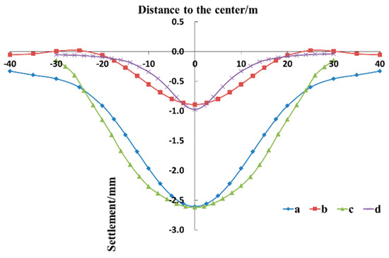
Figure 10.
Comparison of tunnel settlement curves: (a) data computed by the calculation method proposed in this paper when no grouting ring is set, (b) data computed by the calculation method proposed in this paper when a grouting ring is set, (c) data computed by the finite element model when no grouting ring is set, and (d) data computed by the finite element model when a grouting ring is set.
In summary, the settlement curves of the existing tunnel calculated by the theoretical method proposed herein are consistent with those obtained from the finite element modeling; also, both methods follow the same change trend before and after installing the grouting ring. Therefore, we can conclude that this method has an acceptable degree of accuracy in calculating the settlement of the existing tunnel reinforced with the grouting ring. The developed method can be utilized to analyze the effect of the grouting ring on reducing tunnel crossing disturbance and can have great significance in the actual project design.
4. Influence of Individual Factors
4.1. Influence of Length of Grouting Rings
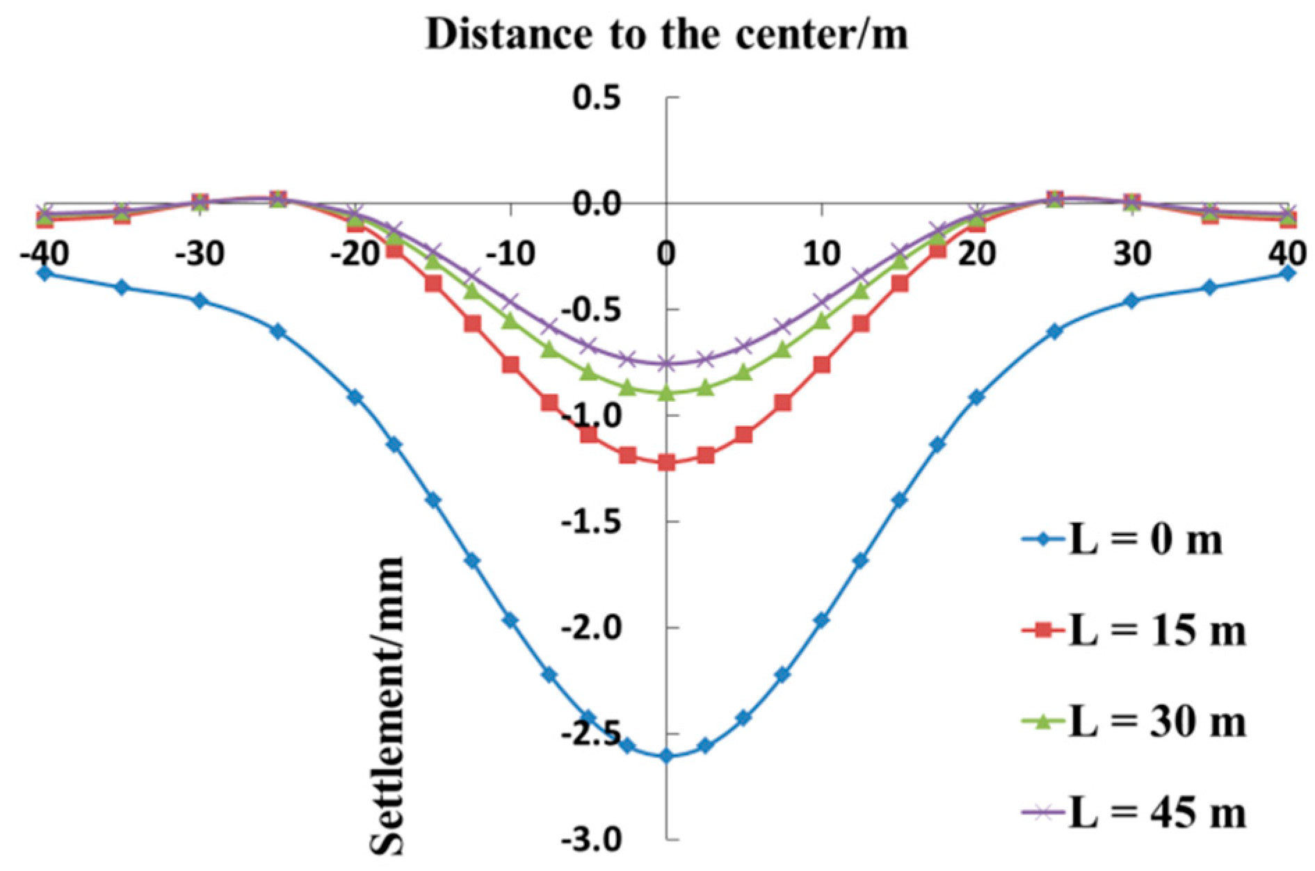
Under the standard working conditions of the calculation example, the length of the grouting ring is set at 0, 15, 30, and 45 m, and the other parameters remain unchanged. The grouting rings fulfill the requirements of the symmetrical arrangement along the crossing center.
Figure 11 shows the comparison between the vertical displacement curves of the existing tunnel at different lengths of the grouting section. It is obvious that, first, in the main settlement area near the crossing center, the settlement curves have a normal distribution under all the working conditions, and the maximum settlement of the existing tunnel occurs in the crossing center. When L is 0, 15, 30, and 45 m, the maximum central settlement is equal to 2.61, 1.22, 0.89, and 0.76 mm, respectively. Second, the installation of the grouting ring can effectively reduce the settlement of the existing tunnel, but as the length of the grouting section increases, the reinforcing effect will gradually weaken. This indicates that the chiefly affected area of the existing tunnel is near the crossing center, under which the new tunnel passes, so setting the grouting ring for the insignificantly impacted areas will reduce the cost-effectiveness of the grouting ring protection method.
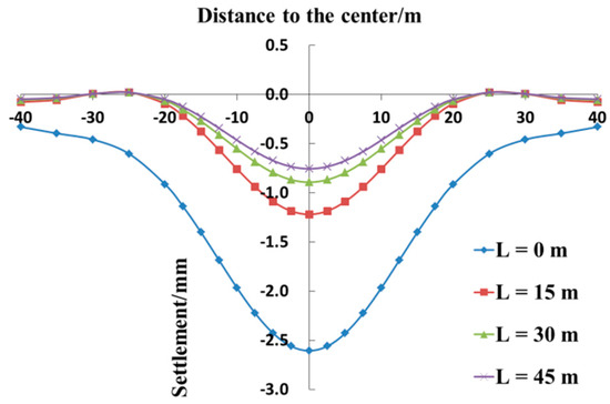
Figure 11.
Comparison of the settlement values of the existing tunnels at different lengths of the grouting ring.
4.2. Influence of Thickness of Grouting Rings
Under the standard working conditions of the calculation example, the thickness of the grouting ring is set at 1.0, 1.5, 2.0, and 2.5 m, and the other parameters remain unchanged.
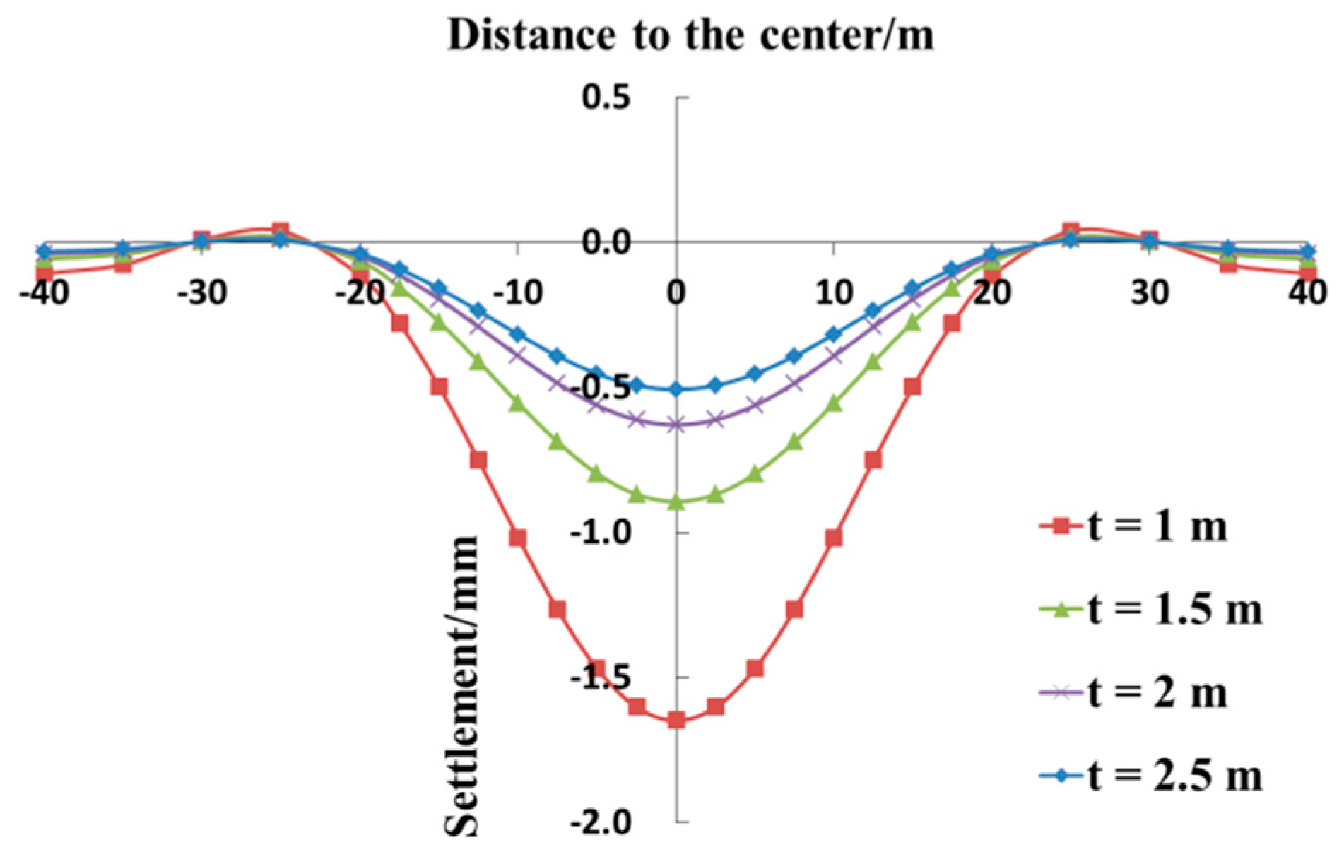
Figure 12 depicts the comparison between the vertical displacement curves of the existing tunnels at different thicknesses of the grouting ring. First, as the thickness of the grouting ring increases, the settlement value of the existing tunnel decreases continuously. When t is equal to 1.0, 1.5, 2.0, and 2.5 m, the maximum settlement in the center of the existing tunnel is 1.65, 0.89, 0.63, and 0.51 mm, respectively. Second, an increase in the thickness of the grouting ring can strengthen the protective effect and can reduce the settlement of the existing tunnel, but it increases the cost of protection gradually. Third, the variation in the thickness of the grouting ring has a negligible effect on the settlement range of the existing tunnel, and the chiefly impacted section is always within 20 m from both sides of the center of the existing tunnel.
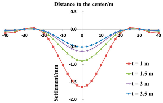
Figure 12.
Comparison of the settlement values of the existing tunnels at different thicknesses of the grouting ring.
5. Conclusions
This paper compared the settlement curves of the existing tunnel before and after the grouting ring is created. The calculation results are in good agreement with the data obtained from the finite element model. Thus, the method developed in this paper can be utilized to calculate the vertical displacement of the existing tunnel before and after installing the grouting ring. The study found that the installation of the grouting ring on the outer wall of the existing tunnel can effectively reduce the settlement caused by the tunneling shield passing beneath. Furthermore, increasing the length and the thickness of the grouting ring can strengthen the protection of the existing tunnel and can effectively reduce the settlement of the tunnel; however, with an increase in the length and the thickness of the grouting ring, the reinforcing effect will gradually lessen.
Existing tunnel grouting ring technology is used in a large number of shield crossing projects, but there is currently no calculation method to evaluate the protection effect of this technology on existing tunnels. According to the research in this paper, the grouting ring installed on the existing tunnel can reduce the impact of shield excavation. The protective effect of the grouting ring is affected by the length and thickness of the grouting ring. If the length and thickness are too small, the protection effect is too small, and it is not enough to form a protection effect for the existing tunnel. On the contrary, if the length and thickness of the grouting ring are too large, it will cause waste. Therefore, it is very important to rationally design the parameters such as the length and thickness of the grouting ring. The theoretical calculation method provided in this paper can be used to calculate the vertical deformation of existing tunnels by substituting the design parameters of grouting rings, so as to verify the rationality of the design parameters of grouting rings.
This work simplifies the effect of the grouting ring on the existing tunnel and believes that the main action of the grouting ring is to accelerate the reduction of stress and strengthen the foundation soil of the existing tunnel. In actual projects, the grouting rings are often used in combination with other control measures. Nevertheless, in order to analyze the influence of the grouting ring on the settlement of the existing tunnel more clearly, it was examined as an individual factor herein. Thus, the impact of the grouting rings can be evaluated combined with other control measures in future research.
Author Contributions
Conceptualization, Y.Q.; methodology, Y.Q.; software, Y.Q. and Y.X.; validation, Y.Q., G.W., Q.W. and Y.X.; data curation, Y.Q.; writing—original draft preparation, Y.Q.; writing—original draft preparation, Y.Q., G.W., Q.W. and Y.X. All authors have read and agreed to the published version of the manuscript.
Funding
This research was supported by the National Natural Science Foundation of China (Grant No. 51778576).
Institutional Review Board Statement
Not applicable.
Informed Consent Statement
Not applicable.
Data Availability Statement
The data used to support the findings of this study are included within the article.
Acknowledgments
We are grateful to other members of our research team (Wang, X., Zhang, X.H., Y.U. and G.H.) for their technical support.
Conflicts of Interest
The authors declare no conflict of interest.
References
- Sun, L.; Liu, G.; Wang, Z.; Wu, S.; Hong, C. The shield tunnel obliquely crossing over an existing pipeline: A numerical analysis. Civ. Eng. Urban Plan. 2012, 2012, 748–754. [Google Scholar]
- Yin, M.; Jiang, H.; Jiang, Y.; Sun, Z.; Wu, Q. Effect of the excavation clearance of an under-crossing shield tunnel on existing shield tunnels. Tunn. Undergr. Space Technol. 2018, 78, 245–258. [Google Scholar] [CrossRef]
- González, C.; Sagaseta, C. Patterns of soil deformations around tunnels. Application to the extension of Madrid Metro. Comput. Geotech. 2001, 28, 445–468. [Google Scholar] [CrossRef]
- Han, Y.H.; Ye, W.H.; Wei, Q.F. Research on the Influence of New Shield Tunnel to Adjacent Existing Tunnel. Appl. Mech. Mater. 2013, 295–298, 2985–2989. [Google Scholar] [CrossRef]
- Zhang, Z.; Huang, M. Geotechnical influence on existing subway tunnels induced by multiline tunneling in Shanghai soft soil. Comput. Geotech. 2014, 56, 121–132. [Google Scholar] [CrossRef]
- Li, X.; Yuan, D. Response of a double-decked metro tunnel to shield driving of twin closely under-crossing tunnels. Tunn. Undergr. Space Technol. 2012, 28, 18–30. [Google Scholar] [CrossRef]
- Zhang, Z.G.; Zhang, M.X.; Wu, H.M.; Xiao, X. 3D numerical simulation for mechanical influence of multi-line tunneling on existing tunnel in soft clay GB/T 7714. In Proceedings of the IET International Conference on Smart & Sustainable City, Shanghai, China, 6–8 July 2011. [Google Scholar]
- Jin, D.; Yuan, D.; Li, X.; Zheng, H. Analysis of the settlement of an existing tunnel induced by shield tunneling underneath. Tunn. Undergr. Space Technol. 2018, 81, 209–220. [Google Scholar] [CrossRef]
- Zhang, X.; Zhang, M.; Li, L. Research on Construction Disturbance Caused by Multi-Line Overlapped Shield Perpendicularly Crossing. Ground Improv. Geosynth. 2014, 502–513. [Google Scholar] [CrossRef]
- Yang, J.; Liu, C.; Chen, Q.; Xie, X. Performance of overlapped shield tunneling through an integrated physical model tests, numerical simulations and real-time field monitoring. Undergr. Space 2017, 2, 45–59. [Google Scholar] [CrossRef]
- Jin, D.; Yuan, D.; Li, X.; Zheng, H. An in-tunnel grouting protection method for excavating twin tunnels beneath an existing tunnel. Tunn. Undergr. Space Technol. 2018, 71, 27–35. [Google Scholar] [CrossRef]
- Peng, H.; Dong, Z.Y.; Liu, Y.L. Research on Deformation Influence of Shield Undercrossing the Existing Metro Double Shield Tunnel. Adv. Mater. Res. 2014, 1065–1069, 378–382. [Google Scholar] [CrossRef]
- Yang, C.-Y.; Ma, W.-H.; Peng, H. Research on the settlement control of existing shield tunnels affected by construction of underneath dual shield tunnels. J. Railw. Eng. Soc. 2018, 35, 91–98. [Google Scholar]
- Mindlin, R.D. Force at a point in the interior of a semi-infinite solid. Physics 1936, 7, 195–202. [Google Scholar] [CrossRef]
- Wei, G.; Yu, G.-H.; Yang, B. Calculation of existing shield tunnel shearing dislocation platform deformation due to undercrossing new shield tunnel undercrossing. J. Hunan Univ. 2018, 45, 103–112. [Google Scholar]
- Zhou, S.-H.; He, C.; Xiao, J.-H. Energy method for calculation deformation of adjacent shield tunnels due to foundation pit excavation considering step between rings. China Railw. Sci. 2016, 37, 53–60. [Google Scholar]
- Wei, G.; Zhang, X.-H. Calculation of rotation and shearing dislocation deformation of underlying shield tunnels due to foundation pit excavation. J. Cent. South Univ. Sci. Technol. 2019, 50, 2273–2284. [Google Scholar]
- Shen, S.-L.; Wu, H.-N.; Cui, Y.-J.; Yin, Z.Y. Long-term settlement behavior of metro tunnels in the soft deposits of Shanghai. Tunn. Undergr. Space Technol. 2014, 40, 309–323. [Google Scholar] [CrossRef]
- Wei, G.; Jiang, X.; Lin, X. Research on additional load of adjacent underground pipelines caused by ground penetrating shield tunneling. Chin. J. Undergr. Space Eng. 2019, 15, 234–241. [Google Scholar]
- Guo, Y.; He, S.; Guan, X.; Liu, X.B. Theoretical study of plane equivalent elastic model of composite soils with fracturing grouting. Rock Soil Mech. 2015, 36, 2193–2208. [Google Scholar]


Publisher’s Note: MDPI stays neutral with regard to jurisdictional claims in published maps and institutional affiliations. |
© 2021 by the authors. Licensee MDPI, Basel, Switzerland. This article is an open access article distributed under the terms and conditions of the Creative Commons Attribution (CC BY) license (http://creativecommons.org/licenses/by/4.0/).