Abstract
To study the influence of the near-fault vertical earthquake, the beam-spring-damper-pier model is used to simulate the double-span continuous beam bridge. The transient wave function expansion method and the indirect mode function method are used to calculate the seismic response of the bridge. The theoretical solutions of the contact force and displacement response of the bridge under vertical earthquake excitation near-fault are derived. By using piers with three different heights, the influence of vertical separation on pier-bending failure is analyzed reasonably. The results show that under the near-fault earthquake action, the split has a certain influence on the pier failure. Moreover, the stiffness and damping of the bearing have an influence on the pier failure, and the change of the maximum pier height has different effects. Therefore, for bridges of different sizes, it is of great significance to select the appropriate stiffness and damping bearings to reduce pier failure.
1. Introduction
As a transportation hub, under the action of an earthquake, the destruction of the bridge not only destroys the transportation counterparts but also affects the subsequent post-disaster rescue. Moreover, it is difficult to repair bridges damaged by an earthquake, which seriously affects early transportation recovery [1,2]. In the past, research on bridge damage was mainly concentrated in the horizontal direction [3,4,5], but in recent years, considering the influence of vertical seismic action on the structure, many scholars at home and abroad have conducted a lot of research. Vertical seismic action will change the axial force of the pier, and the increased axial force may cause the pier to be damaged under compression [6,7,8,9]. In view of the possible bending and shear damage caused by the axial force on the pier, a large number of experiments have been conducted, and it is proposed that under the action of a vertical earthquake, the fluctuation of the axial force will have an impact on the pier’s shear performance [10,11,12,13]. When the axial force of the bridge pier decreases or even tensile stress occurs, it will reduce or lose the horizontal shear resistance of the concrete, causing the shear strength of the pier to weaken. The fluctuation of the axial force of the pier will also weaken the bending resistance and ductility of the concrete pier. Under the combined action of horizontal and vertical earthquakes, the pier will be damaged by bending [10,12,13]. For the main beam, the vertical seismic action will increase the mid-span bending moment and even cause structural damage [10,14].
In the above studies of the vertical component’s influence on the bridge, the ratio of the vertical seismic acceleration to the horizontal acceleration is set to not exceed 2/3. However, with the renewal of seismic monitoring equipment in recent years, more and more seismic data show that under the action of near-fault earthquakes, the acceleration amplitude of vertical earthquakes will exceed the limit specified by the code. For example, the maximum vertical acceleration recorded by the Northridge earthquake is 1.18 g, and the ratio of vertical seismic acceleration to horizontal acceleration (V/H) is up to 1.79 [15]. The peak vertical acceleration on the ground of the Kobe earthquake is twice the peak lateral acceleration [16]. The 9 seismic record curves of the Wenchuan earthquake in Sichuan within 20 km from the fault show that the average value of V/H is 0.89 and the maximum value is 1.2 [17]. The analysis of the vertical acceleration response spectrum of the near-fault earthquake found that the near-fault earthquake has its unique characteristics and cannot be roughly treated as 2/3 of the horizontal seismic acceleration [18]. Unlike most building structures, the span of the bridge is large, and vertical vibration will cause large vertical deformation of the main girder. Strong vertical seismic excitation may reduce the contact force of the bridge support [18], resulting in the friction weakening between the main girder and the bridge pier. The vertical vibration will cause a large vertical deformation of the main girder. Strong vertical seismic excitation may reduce the contact force of the bridge support [18], resulting in the friction weakening between the main girder and the bridge pier. In addition, most bridges in China use plate rubber bearings, and the main girder is placed directly on the support [19]. The support and the main girder lack a tensile connection. When the vertical excitation is too strong, the main girder and the pier may be separated. In the 1989 Loma Prieta earthquake in the United States [20], the highway bridge collapsed due to the vertical earthquake, and its piers passed through the bridge deck and stood upright. This type of damage may cause the main girder to be thrown up under the action of a strong vertical earthquake. When it falls again, it will have a huge collision force with the pier, causing the pier to penetrate the bridge deck. In addition, collisions caused by separation may also cause local damage to the bridge. Tanimura et al. believed that the damage of the support was caused by the high stress caused by the collision with the bridge support after the bridge span jumped [21]. In addition, the impact caused by separation may also lead to local damage to the bridge. Tanimura et al. [21] considered that the damage of the bearing was caused by the high stress caused by the collision between the girder and the bearing after the main girder jumped.
Most of the previous research is based on the constant contact between the girder and the pier, ignoring the possible contact-separation-recontact displacement response process of the pier and girder under the action of the near-fault earthquake. The purpose of this research is to establish a theoretical method to research the effect of vertical separation of piers and girders on bridge displacement response. By using the double-span continuous beam model to simulate the seismic response of the bridge, the transient wave function is expanded into a series of eigenfunctions [22]. By introducing the indirect wave modal method [23] to solve the collision force response, the theoretical solution of the vertical and longitudinal contact force and displacement response of the girder and piers is obtained. The effect of the pier–beam separation on the longitudinal relative displacement of the pier–beam is calculated. The influence of pier size on the bending failure of the pier bottom is also studied.
2. Theoretical Model and Vertical Displacement Calculation
In this study, a double-span continuous girder highway bridge with a low vertical natural vibration period was selected. The model is shown in Figure 1. The single span of a continuous girder is L; the cross-sectional area is ; the elastic modulus of the section is ; the moment of inertia of the section is . The height of the pier is H; the cross-sectional area is ; the modulus of elasticity of the section is ; the moment of inertia of the section is . The density of the main girder and bridge piers are both . The self-weight of the main girder is set to a uniform load q. The compressive stiffness of the rubber bearing is ; the shear stiffness is . Ignoring that the bearing deformation exceeds the shear deformation limit, the rubber bearing damping is , and the vibration damping of the concrete beam itself is .
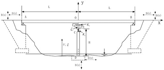
Figure 1.
Double-span continuous beam bridge model.
In the longitudinal direction, D(t) is used to simulate the seismic excitation. The main girder uses St. Venant rods to simulate axial deformation, and the pier uses the Bernoulli–Euler beams to simulate bending deformation. In the vertical direction, B(t) is used to simulate the seismic excitation. The main girder adopts Bernoulli–Euler beam to simulate bending deformation, and the bridge pier adopts the the St. Venant rod to simulate axial deformation. In the lateral direction, due to the limitation of some bridge blocks, the influence of the pier and girder separation condition on the bridge’s lateral displacement response is ignored. Only the bending failure of the bottom of the pier under the coupling of longitudinal and vertical is considered.
The model used in this study is a double-span continuous bridge. The calculation model is shown in Figure 1. The main beam is a prestressed box beam, and the pier is a double-column circular pier. The length of the main girder L = 38 m. The round lead high-damping rubber bearing is used between the main girder and the piers. In the vertical direction, the hysteresis curve of the bearing is long and narrow, ignoring the damping of the vertical bearing. In the horizontal direction, the damping of the bearing equals 20%. In the vertical direction, the stiffness of the bearing is N/m; in the horizontal direction, the stiffness is N/m. To simplify the calculation, this study makes the following assumptions:
- (1).
- When the bridge is forced to resonate, the structural force and displacement response are always calculated by elastic deformation.
- (2).
- During seismic action, there are often stops in the lateral direction. This study only considers the coupling of vertical and longitudinal seismic activities.
- (3).
- Ignore the difference in the arrival time of the horizontal and vertical seismic waves, assuming that the earthquakes in both directions are excited at the same time.
- (4).
- The bottom of the abutment and pier is set on the hard rock, and the interaction between rock and soil is ignored.
- (5).
- The gap between the abutment and girder is ignored.
2.1. Theoretical Solution of Displacement Response of Bridge in Vertical Contact Stage
The wave equations of girder AB and pier CD can be described as the following:
In these equations, is the deflection of the beam; is the axial displacement of pier.
The boundary condition of bridge displacement is:
and the displacement continuity condition at the middle of the main girder is:
The continuity condition of the shear force and displacement between girder, pier, and support are:
The vertical displacement field , of the girder can be divided into static displacement , rigid body displacement , and dynamic deformation .
Dynamic displacement satisfies the wave equation, continuity condition, equilibrium differential equation, and force boundary condition.
Static displacement of the bridge is as follows:
where .
The displacement of the rigid body of the bridge is as follows:
The dynamic deformation part of the structure can be expanded as an infinite series of wave mode products:
The equation includes the bending wave function, , of the girder, the longitudinal wave function, , of the pier, and the time function, .
The wave model function is solved by the characteristic equations. The characteristic equations of the main girder and pier are, respectively:
where: (n = 1,2,3, ) is the natural frequency of bridge structure, is the coefficient related to the beam flexural wave speed, and is the rod phase speed.
Flexural wave modes of the main girder and longitudinal wave of the pier can be described as:
where and are the wave numbers of the flexural wave and longitudinal wave, respectively. are the coefficients.
The boundary conditions of the characteristic equation are as follows:
The continuity conditions of feature direction are as follows:
The orthogonal consistency of the bending wave and longitudinal wave can be obtained by Equations (9) and (10):
By introducing Equations (11) and (12) into Equation (10), the wave functions of the bridge structure can be obtained as follows:
By introducing Equation (14) in Equation (12), one can solve and .
Through the orthogonality condition, the time function, , differential equation of the bridge can be obtained:
By Laplace transformation, can be obtained:
In Equation (16), .
2.2. Corresponding Theoretical Solution of Bridge Vertical Separation Stage Displacement
In the separation process, the beam and the rod do not interact and move at their own characteristic frequencies, and , respectively.
The displacement response of the main girder and pier can be decomposed into static displacement, rigid displacement, and dynamic deformation, and the main beam does not need to be decomposed into two segments.
The vertical static displacement and rigid displacement of the bridge structure are as follows:
The wave equations of girder AB and pier CD can be described as the following equations:
The wave mode functions of the main girder and pier are:
where are the coefficients.
The boundary conditions of the characteristic equation are as follows:
The wave functions of the bridge structure can be obtained as follows:
For the main girder and pier, the wavenumber is:
Based on the orthogonality of the wave mode function, the coefficient can be obtained as:
If the separation contact phenomenon occurs many times, it can be assumed that is the time variable of the k-th collision, and is the time variable of the k-th separation.
In the k-th separation process, the dynamic displacement responses of the main girder and pier are as follows:
The initial displacement and velocity of the girder and pier structure are considered only by the first mode. By viewing the residual rate and deformation of the last process, the contact separation process is solved continuously.
2.3. Corresponding Theoretical Solution of Bridge Vertical Separation Stage Displacement
When the relative displacement between the girder and pier is less than zero, it is considered that the girder and the pier are in contact again. At the moment of collision contact, the overall frequency of the bridge cannot be calculated. The use of resonance frequency calculation will produce large dispersion, and it is difficult to ensure the convergence of the calculation results. In the vertical impact process, the dynamic deformation after contact collision is divided into the impact force deformation and dynamic wave deformation . The indirect mode superposition method [23] calculates the structural displacement under the impact force. Initial contact time is + + = 0. In the subsequent vertical collision process, the main beam and the bridge pier have no vertical contact force at the initial moment. In addition, the static displacement of the girder and the pier is zero. It can be concluded that the dynamic displacement of the bridge at the initial moment is:
The collision displacements of the structure are:
where is the generalized collision force. and are the coordinates of the collision point of the main beam and pier, respectively. is the impact force. The positive and negative signs in Equation (26) denote the relationship between force and displacement direction, respectively.
where are modal masses.
The impact force, , when the girder and pier are separated. At the impact stage, the collision force, , displacement response is:
By introducing Equation (26) in Equation (28), the vertical load and the collision contact part of bridge structure displacement can be calculated by using the step-by-step integration method.
The partial time function of dynamic deformation is as follows:
The dynamic deformation of the bridge can be expressed as follows:
3. Numerical Analysis and Calculation
This paper chooses a double-span continuous girder bridge as an example to carry out research. The bridge uses a prestressed box girder. The pier comprises two circular concrete columns, and each pier has longitudinal steel bars and annular stirrups. Figure 2 shows the cross-section and detailed dimensions of the bridge.
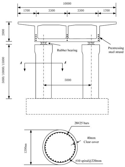
Figure 2.
Dimensions and details of the bridge elevation and section drawings.
In the vertical direction, the hysteresis curve of the rubber bearing is long and narrow. To simplify the calculation, the bearing is a spring model with stiffness: . In the longitudinal direction, the bearing is a spring-damping model, where the shear stiffness is , and the damping is = 5%. When the bridge elastically vibrates, the damping of the main girder and pier is set to = 5%.
3.1. Effect of Vertical Separation on the Failure of Bridge Piers
Since the longitudinal natural vibration period and vertical natural vibration period of the bridge are different, three height piers are selected for analysis to more accurately analyze the influence of the pier and girder separation on the damage of the pier. The selection criteria are: , and . The three height piers selected in this article are H = 5 m, 10 m, and 15 m.
It is necessary to select the appropriate time step when using the above formula. The axial wave velocity of the main girder is = 3503 m/s, and the bending wave velocity is = 2697 m/s. The axial wave velocity of the pier is = 3492 m/s, and the bending wave velocity is = 1060 m/s. To accurately calculate the displacement of the bridge in the calculation time, the selected time step must be less than the time required for the bending waves and axial waves to pass through the girder and pier: × 10−3 s. Hence, time-step increments of 1.0 × 10⁻³ s are used for research. Considering the influence of damping on the displacement response of the bridge, the modal number of the bridge structure is selected as N = 5.
Figure 3 shows the vertical and longitudinal displacement responses of the bridge under three pier heights when the seismic excitation period T = 0.22 s, take , and ignore the arrival time difference between horizontal and vertical waves. When H = 5 m (), the girder and the pier are separated seven times in 2 s, and the first separation occurs at t = 0.436 s. The maximum vertical collision force between the girder and pier is 34.66 MN, which is 2.84 times the static contact force. In the longitudinal direction, the separation has little effect on the relative displacement of the pier and girder, and the maximum relative displacement is 2.2 mm regardless of the separation. When , the separation of the girder and pier caused by vertical resonance has little effect on the bridge displacement response.
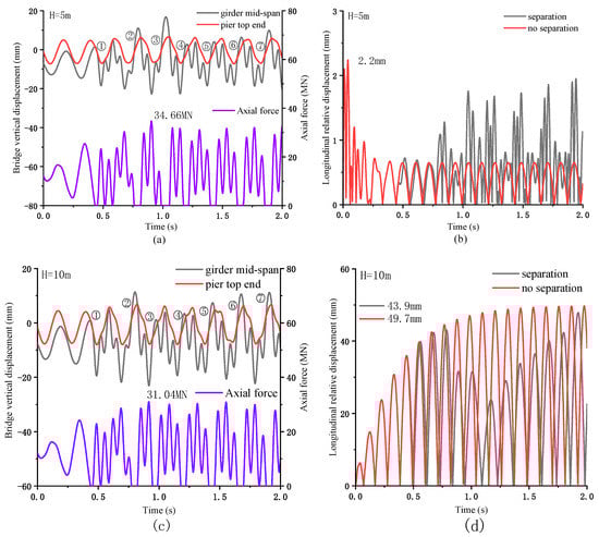
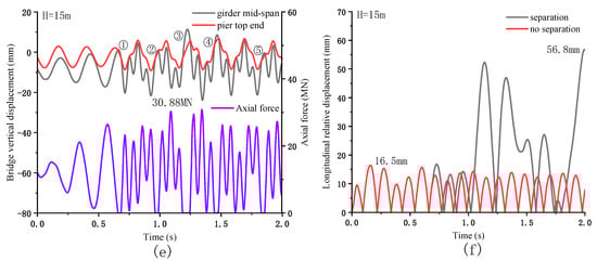
Figure 3.
Bridge displacement response: (a) The bridge’s vertical displacement and contact force response when H = 5 m; (b) The relative displacement response of the pier and girder under two conditions when H = 5 m; (c) The bridge’s vertical displacement and contact force response when H = 10 m; (d) Relative displacement response of pier and girder under two conditions when H = 10 m; (e) The bridge’s vertical displacement and contact force response when H = 15 m; (f) The relative displacement response of the pier and girder under two conditions when H = 15 m.
When H = 10 m (), under the excitation of the seismic excitation period T = 0.22 s, large resonance effects will be produced in both the vertical and longitudinal directions. In the vertical direction, the girder and the pier were separated seven times in 2 s, and the first separation occurred at t = 0.456 s. The maximum vertical contact force of the bridge is 31.04 MN, which is 2.57 times the static contact force. Due to the longitudinal resonance effect, the maximum relative displacement of the pier and girder increased significantly. When the separation is considered, the maximum relative displacement is 49.7 mm, and when the split is ignored, the result is 43.9 mm. It can be seen that when , the split has little effect on the bridge’s longitudinal displacement response.
When H = 15 m, . The separation times of the main girder and piers within 2 s are reduced to 5 times, and the initial separation time is t = 0.627 s. The maximum vertical collision force of the pier girder is 30.88 MN, which is 2.56 times the static force. The separation in the longitudinal direction has a greater impact on the bridge displacement. When the separation is neglected, the maximum relative displacement of the pier and girder is 16.5 mm. When the separation is considered, the maximum is increased to 56.8 mm, an increase of 244%. Therefore, separation has a more significant impact on the damage of the bridge when .
For rubber-bearing bridges, the pier-bending damage is mainly concentrated at the bottom of the pier. According to the force analysis of the model in Figure 4, it can be seen that under the action of the near-fault vertical earthquake, the bending damage at the bottom of the pier is primarily composed of three parts: 1. Abrupt eccentric collision; 2. The shear force of bearing; 3. The forced vibration of bridge pier. The three bending moments are represented by , and , respectively.
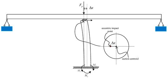
Figure 4.
Schematic diagram of the bending moment at the bottom of the pier.
When the girder and the bridge pier are not separated, it is assumed that the vertical contact force of the pier–girder is twice the static contact force. At the same time, due to the difference in the arrival time of the horizontal and vertical seismic waves, the bending moment caused by the abrupt eccentric vertical collision is ; the bending moment caused by the bearing shear is . The bending moment caused by the forced vibration of the pier is , where is the eccentric impact amplification factor, which can be calculated as reference [24].
Figure 5a shows the bending failure of the pier bottom under different pier heights. When H = 5 m, after the girder and pier are separated, the total bending moment at the bottom of the pier is almost unchanged. However, the vertical separation caused a substantial increase in the vertical contact force between the girder and the pier, which reduced the allowable bending moment of the pier, increase the risk of pier damage. When H = 10 m, , the longitudinal direction of the pier produces greater resonance. Although the collision after separation reduces the allowable bending moment of the pier, since the bending moment at the bottom of the pier greatly exceeds the permissible value, the separation has little effect on the damage of the pier. When H = 15 m, ignoring the separation of the bridge, the piers are in a safe interval. When considering separation, the bending moment at the bottom of the pier is significantly increased due to the change in the relative longitudinal displacement of the pier girder, and the vertical collision reduces the allowable bending moment of the pier. The forced vibration of the pier produces bending moment damage.
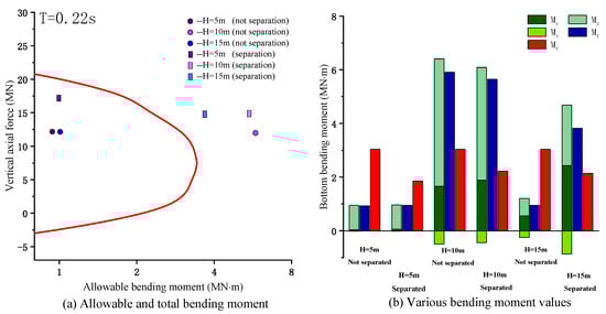
Figure 5.
Bending moment at the bottom of the pier: (a) Total bending moment and an allowable bending moment of the pier bottom under two periods; (b) The direction and magnitude of various bending moments at the bottom of the pier.
Figure 5b shows the changes of various bending moments at the bottom of the piers at the three pier heights when they are separated or not. When H = 5 m, the relative longitudinal displacement of the pier–girder is small, and the bending moment at the bottom of the pier is mainly caused by forced vibration. When H = 10 m, although the longitudinal relative displacement of the pier–girder increases considerably, the bending moment at the bottom of the pier is mainly caused by the longitudinal resonance. When H = 15 m, although the bending moment is mainly due to forced resonance. However, the separation of the pier girder will increase the relative longitudinal displacement and vertical collision force. The bending moment generated by the eccentric collision will aggravate the damage of the pier.
3.2. Influence of Bearing Damping on the Failure of Bridge Piers
Considering the influence of bearing damping on bridge displacement, the damping range selected in this paper is %35%. The calculation results in Figure 6 show the separation of the bridge displacement under different bearing damping. When H = 5 m, the downward trend of the maximum longitudinal relative displacement under the two conditions is the same, but the influence of damping on the structure under the separated condition is lower than under the condition of constant contact. When H = 10 m, whether separated or not, with the increase of damping, the longitudinal relative displacement of the pier–girder can be greatly reduced, and the two conditions of the reduction range are consistent. When H = 15 m, the relative longitudinal displacement of the pier girder decreases with the bearing damping increase. Under the separation condition, the maximum relative displacement was reduced from 56.8 mm to 40.2 mm, reducing by 29.2%. When considering separation, the ultimate value is reduced from 16.5 mm to 13.8 mm, a decrease of 16.4%.
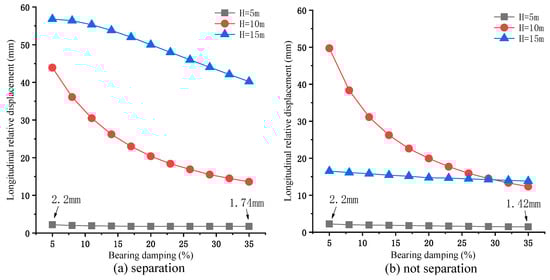
Figure 6.
Longitudinal relative displacement of pier–girder under different damping: (a) consider the break of girder pier when T = 0.22 s; (b) ignore the separation of girder–pier when T = 0.22 s.
Figure 7 shows the variation of various bending moments at the bottom of the pier with the bearing’s damping when H = 5 m (). Under the damping change, the relative longitudinal displacement of the pier–girder has been kept small, and the bending moment caused by the vertical force of the girder and the shear force of the bearing at the bottom of the pier can be ignored. The bending moment generated by the bridge pier’s forced vibration decreases with the increase of this damping, but the decreasing trend is different under the two conditions. When the separation is ignored, decreases monotonously with the rise of the bearing damping. When considering the break, the previous stage of decreases with the growth of damping. When > 15%, the value of remains stable.
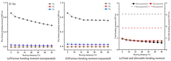
Figure 7.
Bending moment at the bottom of the pier when H = 5 m: (a) changes of various bending moments with damping under unseparated conditions; (b) changes of various bending moments with damping under separated conditions; (c) changes of total and allowable bending moment with damping under two conditions.
Figure 7c shows the total and allowable bending moment at the bottom of the pier under the two conditions. When the break is neglected, the axial force is twice the static force when calculating the allowable bending moment. When considering separation, the axial force is the maximum collision force. It can be seen that although damping is less effective in reducing the total bending moment when considering separation, the piers are in a safe range in both cases.
When H = 10 m (), the various bending moments of the pier change with damping, as shown in Figure 8a,b. Compared with H = 5 m, , and have larger bending moment amplitudes at the bottom of the pier, but the proportion of the total bending moment is still low. The damage is mainly due to forced resonance. Figure 8c shows that the total bending moment at the bottom of the pier has little difference whether it is separated or not.
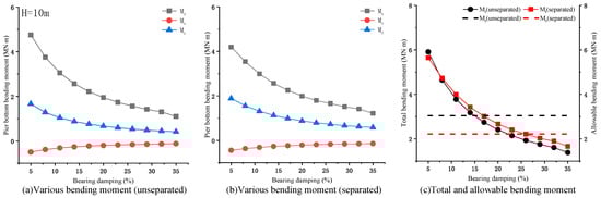
Figure 8.
Bending moment at the bottom of the pier when H = 10 m: (a) changes of various bending moments with damping under unseparated conditions; (b) changes of various bending moments with damping under separate conditions; (c) changes of total and allowable bending moment with damping under two conditions.
When H = 15 m (), the separation or no separation also greatly influence the bending moment of the pier bottom due to the different relative displacement of pier and girder under the two conditions. Figure 9a,b shows that although the bending moments decrease monotonically with the increase of damping, the bending moments under the separation condition are significantly higher than those without separation. Figure 9c shows that when , the damping has little effect on the flexural failure of the pier. When the separation is ignored, the pier is in the safe zone. However, when the pier is separated, the increased relative displacement makes the bending moment at the bottom of the pier increase significantly. The pier is always in the unsafe range.
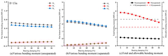
Figure 9.
Bending moment at the bottom of the pier when H = 15 m: (a) changes of various bending moments with damping under unseparated conditions; (b) changes of various bending moments with damping under separate conditions; (c) changes of total and allowable bending moment with damping under two conditions.
3.3. Influence of Bearing Stiffness on the Failure of Bridge Piers
The vertical stiffness of the bearing is related to the size and shape of the bearing and the number and thickness of rubber layers. The range of vertical stiffness is N/m. The shear stiffness of the bearing is 1/1000 of the vertical stiffness. The influence of shear stiffness on the longitudinal vibration period is minimal, which is ignored in this study. In the range of vertical stiffness variation, the vertical natural vibration period of the bridge is = 0.251 s0.232 s, and the content of change is −1.7%6.3%. To simplify the calculation, within the scope of change, this article ignores the influence of the bearing stiffness on the vertical vibration period.
Figure 10a shows the vertical impact force and longitudinal displacement of the bridge under different bearing stiffness. At the same bearing stiffness, the higher the pier height, the lower the vertical impact force. The lower height, the stronger the rigidity of the pier. In addition, the vertical impact force increases monotonously with the increase of bearing stiffness at different pier heights. The maximum impact force increases from 32.4 MN to 40.4 MN when H = 5 m, an increase of 30.2%. When H = 10 m and 15 m, the growth rate is 45% and 42.1%, respectively.
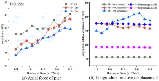
Figure 10.
Contact force and displacement response of bridge under different stiffness. (a) The impact force of girder and pier under different bearing compressive stiffness. (b) The longitudinal relative displacement of girder and pier under different bearing compression stiffness.
The longitudinal relative displacement of the pier–girder is shown in Figure 10b. When H = 5 m, the bearing stiffness does not affect the maximum longitudinal relative displacement of the pier and girder. When H = 10 m, the bearing stiffness has little influence on the maximum longitudinal relative displacement. In both cases, the maximum longitudinal relative displacement is always close and does not change much as the bearing stiffness increases. When H = 15 m and the separation is ignored, the maximum relative displacement remains stable at a small value. While considering the break, the ultimate value fluctuates at a larger amplitude, and the value presents an absolute randomness.
Figure 11 shows the trend of various bending moments at the bottom of the pier under different bearing stiffnesses when H = 5 m (). Although the vertical impact force increases with the bearing stiffness increase, each bending moment remains almost unchanged in the range of variation as the longitudinal relative displacement remains small. Figure 11b shows that the total pier bottom bending moment has little change. Still, the increase of the vertical impact force caused by separation will reduce the allowable pier bottom-bending moment. With the rise in bearing stiffness, the allowable bending moment of the pier bottom decreases gradually. When the stiffness of the bearing is low, the pier is in the safety zone. With the increase of the bearing’s stiffness, the total bending moment of the pier bottom exceeds the allowable bending moment, and the pier is destroyed.
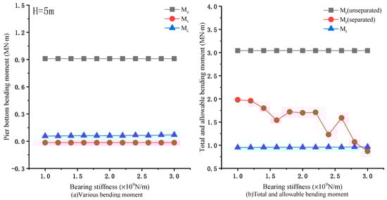
Figure 11.
Bending moment at the bottom of the pier when H = 15 m: (a) changes of various bending moments with bearing stiffness; (b) changes of total and allowable bending moment with bearing stiffness.
When H = 10 m (), there is little difference in the relative longitudinal displacement of the pier–girder with or without separation. When the pier and girder are separated, a greater vertical collision force is generated. This study considers the separation when calculating the bending moments of the pier bottom. With the increase of the bearing’s stiffness, the expansion of the vertical collision force causes to increase slowly. The increase in the shear stiffness of the bearing leads to an increase in . fluctuates in a small range, and its ratio to the total bending moment is large, which plays a leading role in the damage of the bridge pier.
Figure 12b shows that when separation is considered, the allowable bending moment of the pier is lower than when the separation is ignored. Additionally, as the bearing’s stiffness increases, the increased vertical collision force causes the gap to increase gradually. However, due to the longitudinal resonance, the pier produces a large bending moment. The total bending moment of the pier is much larger than the allowable bending moment in the two cases.
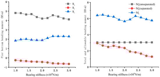
Figure 12.
Bending moment at the bottom of the pier when H = 10 m: (a) changes of various bending moments with bearing stiffness; (b) changes of total and allowable bending moment with bearing stiffness.
When H = 15 m (), the bending moments of pier bottom under different conditions are shown in Figure 13. The changing trend of and is the same as that of H = 10 m, but the bending moment value is more enormous when separated. When the separation is ignored, the remains stable at a small amplitude. However, when the separation is considered, there is a large fluctuation in the larger amplitude.
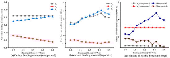
Figure 13.
Bending moment at the bottom of the pier when H = 15 m: (a) changes of various bending moments with bearing stiffness under unseparated conditions; (b) changes of various bending moments with bearing stiffness under separate conditions; (c) changes of total and allowable bending moment with bearing stiffness under two conditions.
When the separation is ignored, the total bending moment and the allowable bending moment of the pier are relatively stable, and the pier is always in a safe range. However, when the separation is considered. The pier is still in the failure zone in the field of bearing stiffness variation. With the increase of the stiffness, the allowable bending moment at the bottom of the pier decreases slowly, the total bending moment increases gradually, and the damage degree of the pier is aggravated.
4. Conclusions
In this paper, the influence of bearing stiffness and damping on pier failure under near-fault vertical earthquake was considered. Firstly, by establishing a girder-spring-damping-rod model, using the transient wave function expansion method and the indirect wave modal function method, the longitudinal and vertical contact force and displacement of the bridge were derived. By considering the influence of the bearing’s stiffness and dampness on pier failure under three different pier heights, the effect of structural separation on bridge failure is proposed. The results of the numerical analysis show that:
- The influence of the pier and girder split on pier failure is different under different pier heights. When and , the vertical earthquake causes the separation of the girder and the pier and produces a great impact force, but the separation has little effect on the longitudinal displacement response of the bridge. When , the separation may increase the longitudinal displacement response of the girder and pier, resulting in the bending failure of the pier.
- When and , the total bending moment at the bottom of the pier changes little no matter whether it is separated or not, and most of the bending moment is produced by the forced resonance of the pier. However, the vertical impact force may reduce the allowable bending moment at the bottom of the pier and cause or aggravate the damage of the pier. When , the separation greatly increases the total bending moment at the bottom of the pier, and the collision also reduces the allowable bending moment. Therefore, in the three cases, neglecting the structural separation at may underestimate the bridge failure.
- When , the bearing damping has little effect on reducing the damage of pier. When , due to the longitudinal resonance effect, the increased damping can greatly reduce the bending moment at the bottom of the pier. When , the bending moment at the bottom of the pier decreases slowly with the increase of damping, especially when considering separation. Simply increasing the bearing damping cannot reduce the damage of the pier.
- With the increase of the bearing’s stiffness, the longitudinal relative displacement of the pier and beam has little change under the three conditions, but the vertical collision force increases monotonously with the increase of pier stiffness. When and , the total bending moment changes little with the increase of stiffness and the allowable bending moment decreases gradually, which may cause or aggravate the pier failure. While , with the increase of bearing stiffness, the total bending moment increases gradually, and the allowable bending moment decreases gradually when considering separation. Compared with the first two cases, the bearing stiffness has the greatest impact on the pier failure.
Author Contributions
Conceptualization, W.A. and G.S.; Formal analysis, W.A.; Methodology, W.A. and G.S.; Project administration, G.S.; Software, W.A.; Supervision, W.A. and G.S. All authors have read and agreed to the published version of the manuscript.
Funding
This study was partially supported by the National Natural Science Foundation of China (51608268) and the Jiangxi Postdoctoral Science Foundation (2019KY57).
Institutional Review Board Statement
Not applicable.
Informed Consent Statement
Not applicable.
Data Availability Statement
Not applicable.
Conflicts of Interest
The authors declare no conflict of interest.
References
- Li, H.N.; Xiao, S.Y.; Huo, L.S. Damage investigation and analysis of Engineering structures in the Wenchuan earthquake. J. Build. Struct. 2008, 29, 10–19. [Google Scholar]
- Zhuang, W.L.; Liu, Z.Y.; Jiang, J.S. Earthquake-induced damage analysis of highway bridges in Wenchuan earthquake and countermeasures. Chin. J. Rock Mech. Eng. 2009, 28, 1377–1387. [Google Scholar]
- Xu, S.Y.; Zhang, J. Axial–shear–flexure interaction hysteretic model for RC columns under combined actions. Eng. Struct. 2012, 34, 548–563. [Google Scholar] [CrossRef]
- Ghannoum, W.M.; Mohle, J.P. Rotation-Based Shear Failure Model for Lightly Confined RC Columns. J. Struct. Eng. 2012, 138, 1267–1278. [Google Scholar] [CrossRef]
- Elwood, K.J. Modelling failures in existing reinforced concrete columns. Can. J. Civ. Eng. 2004, 31, 846–859. [Google Scholar] [CrossRef]
- Cimellaro, G.P.; Domaneschi, M.; Warn, G. Three-Dimensional base isolation using vertical negative stiffness devices. J. Earthq. Eng. 2020, 24, 2004–2032. [Google Scholar] [CrossRef]
- Wilson, T.; Chen, S.; Mahmoud, H. Analytical case study on the seismic performance of a curved and skewed reinforced concrete bridge under vertical ground motion. Eng. Struct. 2015, 100, 128–136. [Google Scholar] [CrossRef]
- Kunnath, S.K.; Erduran, E.; Chai, Y.H.; Yashinsky, M. Effect of near-fault vertical ground motions on seismic response of high overcrossings. J. Bridge Eng. 2008, 13, 282–290. [Google Scholar] [CrossRef]
- Yu, C.P. Effect of Vertical Earthquake Components on Bridge Response. Ph.D. Thesis, University of Texas, Austin, TX, USA, 1998. [Google Scholar]
- Papazoglou, A.J.; Elnashai, A.S. Analytical and field evidence of the damaging effect of vertical earthquake ground motion. Earthq. Eng. Struct. Dyn. 1996, 25, 1109–1137. [Google Scholar] [CrossRef]
- Varecac, D.; Draganic, H.; Gazic, G. Influence of the Vertical Component of Earthquake on Large Span Rc Beams. Tehnicki Vjesnik 2010, 17, 357–366. [Google Scholar]
- Kim, S.J.; Holub, C.J.; Elnashai, A.S. Experimental investigation of the behavior of RC bridge piers subjected to horizontal and vertical earthquake motion. Eng. Struct. 2011, 33, 2221–2235. [Google Scholar] [CrossRef]
- Kim, S.J.; Holub, C.J.; Elnashai, A.S. Analytical Assessment of the Effect of Vertical Earthquake Motion on RC Bridge Piers. J. Struct. Eng. 2011, 137, 252–260. [Google Scholar] [CrossRef]
- Zheng, W.; Leonardo, D.O.; Jamie, E.P. Seismic response of a bridge-soil-foundation system under the combined effect of vertical and horizontal ground motions. Earthq. Eng. Struct. Dyn. 2012, 4, 545–564. [Google Scholar]
- Bozorgnia, Y.; Niazi, M.; Campbell, K.W. Characteristics of Free-Field Vertical Ground Motion during the Northridge Earthquake. Earthq. Spectra 1995, 11, 515–525. [Google Scholar] [CrossRef]
- Wang, G.-Q.; Zhou, X.-Y.; Zhang, P.-Z.; Igel, H. Characteristics of amplitude and duration for near fault strong ground motion from the 1999 Chi-Chi, Taiwan Earthquake. Soil Dyn. Earthq. Eng. 2002, 22, 73–96. [Google Scholar] [CrossRef]
- Wang, D.; Xie, L. Attenuation of peak ground accelerations from the great Wenchuan earthquake. Earthq. Eng. Eng. Vib. 2009, 8, 179–188. [Google Scholar] [CrossRef]
- Wang, C.J.; Shih, M.H. Performance study of a bridge involving sliding decks and pounded abutment during a violent earthquake. Eng. Struct. 2007, 29, 802–812. [Google Scholar] [CrossRef]
- Zuo, Y.; Sun, G.J.; Li, H.J. Comparison and Research of Unseating Prevention Measures in Seismic Codes of China and Foreign Countries. J. Disaster Prev. Mitig. Eng. 2016, 36, 617–623, 639. [Google Scholar]
- Han, W.; Song, C.; Li, Q. Strong ground motion at meizoseisal area & safety of important engineering projects at potential earthquake region. J. Eng. Geol. 2004, 12, 346–353. [Google Scholar]
- Tanimura, S.; Mimura, K.; Nonaka, T.; Zhu, W. Dynamic failure of structures due to the great Hanshin-Awaji earthquake. Int. J. Impact Eng. 2000, 24, 583–596. [Google Scholar] [CrossRef]
- Yang, H.; Yin, X.; Hao, H.; Bi, K. Theoretical Investigation of Bridge Seismic Responses with Pounding under Near-Fault Vertical Ground Motions. Adv. Struct. Eng. 2015, 18, 453–468. [Google Scholar] [CrossRef]
- Xing, Y.F.; Wang, L.J. Analysis of wave propagation in the built-up structures of rod-beam and beam-beam. J. Beijing Univ. Aeronaut. Astronaut. 2013, 30, 520–523. [Google Scholar]
- CJJ 166-2011. Code for Seismic Design of Urban Bridges; Ministry of Housing and Urban-Rural Development of the People’s Republic of China: Beijing, China, 2011.


Publisher’s Note: MDPI stays neutral with regard to jurisdictional claims in published maps and institutional affiliations. |
© 2021 by the authors. Licensee MDPI, Basel, Switzerland. This article is an open access article distributed under the terms and conditions of the Creative Commons Attribution (CC BY) license (https://creativecommons.org/licenses/by/4.0/).