Article

Symmetric and Anti-Symmetric Damping Modes of Trivelpiece–Gould Waves in Weakly and Completely Ionized Plasma Waveguides

1
Department of Physics, Hanyang University, Seoul 04763, Korea
2
Research Institute for Natural Sciences, Hanyang University, Seoul 04763, Korea
3
Department of Applied Physics, Hanyang University, Ansan 15588, Korea
*
Author to whom correspondence should be addressed.
Symmetry 2021, 13(4), 699; https://doi.org/10.3390/sym13040699
Submission received: 15 January 2021 / Revised: 13 April 2021 / Accepted: 15 April 2021 / Published: 16 April 2021

Abstract

:
The collision effects on the low-frequency ion-acoustic Trivelpiece–Gould wave are investigated in weakly and completely ionized plasma waveguides by using the normal mode analysis. In weakly ionized plasma waveguides, it is found that the dependence of the harmonic mode on the absolute value of the scaled damping rate shows the opposite tendency for large and small radii of the cylindrical waveguide. It is also is found that the scaled damping rates for both weakly and completely ionized plasma waveguides decrease with an increase of the electron temperature. It is interesting to note that the scaled damping rate for weakly ionized plasma waveguides shows anti-symmetric behavior when the Trivelpiece–Gould wave propagates in the negative-z direction. However, it is found that the scaled damping rate for completely ionized plasma waveguides shows the symmetric behavior when the Trivelpiece–Gould wave propagates in the negative-z direction.

1. Introduction

The stability analysis of the propagation of linear and nonlinear waves in various physical systems has received considerable attention since the conditions for the stable or unstable modes can provide useful information on the geometrical configuration and the physical characteristics [1]. In plasma environments, it has been shown that the influence of wave–particle and wave–wave interactions plays an important role in the stability of the propagation of linear and nonlinear plasma waves [2]. The condition for the stability of plasma waves in a confined configuration of the bounded plasma has been extensively investigated owing to the wide application of the surface plasma wave [3,4,5,6,7]. It has been shown that the condition for the propagation of surface waves in bounded and semi-bounded plasmas can be explored from the dispersion relation obtained by the surface impedance on the interface between the two different media. Hence, it is obvious that the appropriate boundary conditions at the interface are essential to legitimate the physical properties of surface waves. It is also shown that the cylindrical plasma waveguide has received considerable attention since the space-change wave on the interface of the plasma column would support various harmonic modes owing to the multi-existence of harmonized cylindrical Bessel solutions [8]. The stability of cylindrical plasma with sharp boundaries has been extensively investigated since the non-zero azimuthal component related to a flutelike perturbation is related to the kink instability [9]. In collisional plasmas, it is well known that the influence of collision frequencies causes complex imaginary terms in plasma susceptibilities [10]. Even though there are many investigations on Trivelpiece–Gould waves [11,12,13], we do not have enough information on the effect of collisional damping on the propagation and stability of Trivelpiece–Gould waves in a plasma waveguide containing noble electrons and ions. In addition, the influences of the ion-neutral and ion–ion collisions in weakly and completely ionized plasma waveguides on the Trivelpiece–Gould have not been investigated yet. Hence, this work is motivated to present general descriptions of Trivelpiece–Gould waves propagating in weakly and completely ionized plasma waveguides, including ion-neutral and ion–ion collisions, which seem to affect the dispersive properties. It would be expected that the damping and instability modes could exist in collisional plasma waveguides. Then, in this work, the influence of ion collisions on the low-frequency ion-acoustic space-change wave known as the Trivelpiece–Gould wave are investigated in weakly and completely ionized plasma waveguides. This investigation was conducted to understand the theoretical aspects of the collision effects on the propagation of the low-frequency ion-acoustic Trivelpiece–Gould wave by using the method of normal modes and the separation of variables. Hence, the dispersion relations of the low-frequency ion-acoustic Trivelpiece–Gould waves are derived for weakly ionized plasma waveguides as well as for completely ionized plasma waveguides. The variations of the damping rates owing to ion collisions in weakly and completely ionized plasma waveguides are also discussed.

2. Strum–Liouville Equations for Weakly and Completely Ionized Plasmas

The continuity equation and the momentum equation for the species j of plasma particles are given by, respectively,
n j t + ( n j v j ) = 0 ,
m j n j ( v j t + v j v j ) = P j q j n j φ ,
where n j , v j , m j , P j , q j , and φ are density, velocity, mass, pressure, charge, and electrostatic potential. Here, Poisson’s equation is given by 2 φ = 4 π j = e , i q j n j , where e = electron and i = ion . In the frequency range, k v T i < < ω < < k v T e , the plasma dielectric function ε W ( ω , k ) for weakly ionized plasmas (W) and the plasma dielectric function ε C ( ω , k ) for completely ionized plasmas (C) can be, respectively, expressed as follows [14]:
ε W ( ω , k ) = 1 ω p i 2 ω 2 ( 1 i ν i n ω ) + ω p e 2 k 2 v T e 2 ( 1 + i π 2 ω k v T e ) ,
ε C ( ω , k ) = 1 ω p i 2 ω 2 ( 1 i 8 k 2 v T i 2 5 ω 2 ν i i ω ) + ω p e 2 k 2 v T e 2 ( 1 + i π 2 ω k v T e ) ,
where ω is the frequency, k is the wave number, v T j is the thermal velocity, ω p j = ( 4 π n j q j 2 / m j ) 1 / 2 is the plasma frequency of the species j, ν i n is the ion-neutral collision frequency, and ν i i is the ion-ion collision frequency. Based on the perturbation theory, the small perturbations from the equilibrium values for the density, velocity, and electrostatic potential would be given as n ˜ 1 j = n j n 0 j , v ˜ 1 j = v j v 0 j , and φ ˜ 1 = φ , where the subscript 1 stands for the small perturbing quantity and the subscript 0 for the equilibrium quantity. Here, the time-dependent parts of the perturbed density, perturbed velocity, and perturbed electrostatic potential are given by n ˜ 1 j ( r , t ) = n ˜ 1 j ( r ) e i ω t , v ˜ 1 j ( r , t ) = v ˜ 1 j ( r ) e i ω t , and φ ˜ 1 ( r , t ) = φ ˜ 1 ( r ) e i ω t . In cylindrical coordinates, these perturbed quantities can be represented by the wave-like forms [15,16,17]: n ˜ 1 j ( r ) = n ˜ 1 j ( r ) exp ( i k z + i χ θ ) , v ˜ 1 j ( r ) = v ˜ 1 j ( r ) exp ( i k z + i χ θ ) , and φ ˜ 1 ( r ) = φ ˜ 1 ( r ) exp ( i k z + i χ θ ) , where n ˜ 1 j ( r ) , v ˜ 1 j ( r ) , and φ ˜ 1 ( r ) are the perturbed quantities in the transverse plane, k z = k [ = ( k 2 k 2 ) 1 / 2 ] is the wave number along the axial z-direction, k [ = ( k 2 k z 2 ) 1 / 2 ] is the transverse wave number, and χ is the azimuthal wave number. From Equations (1)–(4), the differential equation for the perturbed electrostatic potential φ ˜ 1 ( r ) would be written as the following self-adjoint form of the Strum–Liouville eigenvalue problem [18]:
L φ ˜ 1 ( r ) = d d r [ r d φ ˜ 1 ( r ) d r ] χ 2 r φ ˜ 1 ( r ) = β μ 2 ( ω , k z ) r φ ˜ 1 ( r ) ,
In Equation (5), the operator L ( d / d r ) ( r d / d r ) χ 2 / r is a self-adjoint operator and β μ 2 ( ω , k z ) = k 2 ε μ ( ω , k z ) , where μ = W for weakly ionized plasma waveguides (WIP) and μ = C for completely ionized plasma waveguides (CIP), respectively,
β W 2 ( ω , k z ) = k z 2 [ 1 ω p i 2 ω 2 ( 1 i ν i n ω ) + ω p e 2 k z 2 v T e 2 ( 1 + i π 2 ω k z v T e ) ]   for   WIP ,
β C 2 ( ω , k z ) = k z 2 [ 1 ω p i 2 ω 2 ( 1 i 8 k z 2 v T i 2 5 ω 2 ν i i ω ) + ω p e 2 k z 2 v T e 2 ( 1 + i π 2 ω k z v T e ) ]   for   CIP .  
Hence, the Strum–Liouville equations for weakly and completely ionized plasma waveguides are, respectfully, found to be
d d r [ r d φ ˜ 1 ( r ) d r ] χ 2 r φ ˜ 1 ( r ) = [ 1 ω p i 2 ω 2 ( 1 i ν i n ω ) + ω p e 2 k z 2 v T e 2 ( 1 + i π 2 ω k z v T e ) ] k z 2 r φ ˜ 1 ( r ) ,
d d r [ r d φ ˜ 1 ( r ) d r ] χ 2 r φ ˜ 1 ( r ) = [ 1 ω p i 2 ω 2 ( 1 i 8 k z 2 v T i 2 5 ω 2 ν i i ω ) + ω p e 2 k z 2 v T e 2 ( 1 + i π 2 ω k z v T e ) ] k z 2 r φ ˜ 1 ( r ) ,

3. Dispersion Relations for Weakly and Completely Ionized Plasmas

The general eigenvalue solutions of the Strum–Liouville equations (Equations (8) and (9)) for weakly and completely ionized plasma waveguides can be represented by φ ˜ 1 ( r ) = χ [ A J χ ( β μ r ) + B N χ ( β μ r ) ] , where the constants A and B are functions of the separation constants χ and β μ , and J χ ( β μ r ) is the χ -th order cylindrical Bessel function, and N χ ( β r ) is the χ -th order Neumann function. Hence, a general solution for φ ˜ 1 ( r , θ ) is found to be φ ˜ 1 ( r , θ ) = β , χ [ A J χ ( β μ r ) + B N χ ( β μ r ) ] ( C e i χ θ + D e i χ θ ) . If the plasma waveguide is assumed to be the azimuthally symmetric cylindrical system, we can set χ 2 [ = ( 2 φ ˜ 1 / θ 2 ) / φ ˜ 1 ] = 0 so that the r-dependence of φ ˜ 1 for the azimuthally symmetric plasma waveguide is put by φ ˜ 1 ( r ) = A J 0 ( β μ r ) + B N 0 ( β μ r ) . Since the singular behavior of the zeroth-order Neumann function N 0 ( β μ r ) for r 0 , this constraint implies B = 0 . In addition, the r-dependence of φ ˜ 1 must be null on the surface of the cylindrical waveguide at r = R , i.e., J 0 ( β μ R ) = 0 . Since J 0 ( β μ r ) has the oscillatory behavior with many zeros, such as J 0 ( α 0 p ) = 0 where α 0 q is the q-th zero of the Bessel function of zeroth order (for example, α 01 = 2.4048 , α 02 = 5.5201 , α 03 = 8.6537 ), the parameter β μ is then obtained by β μ = α 0 q / R , where μ = W for weakly ionized plasma waveguides (WIP) and μ = C for completely ionized plasma waveguides (CIP), respectively. Hence, we can obtain the following equations for weakly and completely ionized plasmas such as
( α 0 q R ) 2 = k z 2 [ 1 ω p i 2 ω 2 ( 1 i ν i n ω ) + ω p e 2 k z 2 v T e 2 ( 1 + i π 2 ω k z v T e ) ]   for   WIP ,
( α 0 q R ) 2 = k z 2 [ 1 ω p i 2 ω 2 ( 1 i 8 k z 2 v T i 2 5 ω 2 ν i i ω ) + ω p e 2 k z 2 v T e 2 ( 1 + i π 2 ω k z v T e ) ]   for   CIP .
Hence, the dispersion relation D W ( ω , k z , ν i n ) for weakly ionized plasma waveguides yields
D W ( ω , k z , ν i n ) = D r W ( ω , k z , ν i n ) + i D i W ( ω , k z , ν i n ) = 1 ω p i 2 ω 2 + ω p e 2 k z 2 v T e 2 + α 0 q 2 k z 2 R 2 + i ( ω p i 2 ν i n ω 3 + π 2 ω ω p e 2 k z 3 v T e 3 ) = 0 ,
where D r W ( ω , k z , ν i n ) and D i W ( ω , k z , ν i n ) denote the real and the imaginary parts of the dispersion function D W ( ω , k , ν i n ) , respectively. The dispersion relation D C ( ω , k z , ν i i ) for completely ionized plasma waveguides is then obtained as
D C ( ω , k z , ν i i ) = D r C ( ω , k z , ν i i ) + i D i C ( ω , k z , ν i i ) = 1 ω p i 2 ω 2 + ω p e 2 k z 2 v T e 2 + α 0 q 2 k z 2 R 2 + i ( 8 ω p i 2 k z 2 v T i 2 ν i i 5 ω 5 + π 2 ω ω p e 2 k z 3 v T e 4 ) = 0 ,
where D r C ( ω , k z , ν i i ) and D i C ( ω , k z , ν i i ) are the real and the imaginary parts of the dispersion function D C ( ω , k z , ν i i ) , respectively. As shown in Equations (12) and (13), the dispersion relations for weakly and completely ionized plasma waveguides are complex functions so that the corresponding frequencies ω ( k z ) should be complex forms, such as ω ( k z ) = ω r ( k z ) + i γ ( k z ) , where the real part of the frequency ω r and the damping rate γ are holding the following constraint condition: ω r ( k z ) > > | γ ( k z ) | . From Equations (12) and (13), we have found that
D r W ( ω , k z , ν i n ) = D r C ( ω , k z , ν i i ) = 1 ω p i 2 ω 2 + ω p e 2 k z 2 v T e 2 + α 0 q 2 k z 2 R 2 ,
with ω = ω r + i γ . The real part of the frequency ω r for weakly and completely ionized plasma waveguides is obtained as
ω r 2 ( k z ) = k z 2 v T e 2 ω p i 2 k z 2 v T e 2 + ω p e 2 + v T e 2 α 0 q 2 R 2 .
From Equations (12), (14) and (15) with ω = ω r + i γ , the small damping rate γ W ( k z ) for weakly ionized plasma waveguides becomes
γ W ( k z ) = D i W ( ω r , k z ) D r W ( ω r , k z ) / ω r = ω p i 2 ν i n ω r 3 + π 2 ω r ω p e 2 k z 3 v T e 3 2 ω p i 2 ω r 3 .
Hence, the absolute scaled damping rate | γ ¯ W | ( = γ W / ω p i ) in the unit of the ion plasma frequency for weakly ionized plasma waveguides is found to be
| γ ¯ W ( k ¯ z ) | = 1 2 [ ν ¯ i n + π 2 1 ω ¯ p e k ¯ z ( k ¯ z 2 + α 0 q 2 R ¯ 2 + 1 ) 2 ] ,
where ν ¯ i n ν i n / ω p i , ω ¯ p e ω p e / ω p i , k ¯ z ( k z λ D e ) is the scaled axial wave number, R ¯ ( R / λ D e ) is the scaled radius of the cylindrical plasma waveguide, and λ D e is the electron Debye length. From Equations (13)–(15) with ω = ω r + i γ , the small damping rate γ C ( k z ) for completely ionized plasma waveguides is found to be
γ C ( k z ) = D i C ( ω r , k z ) D r C ( ω r , k z ) / ω r = 8 k 2 v T i 2 ω p i 2 ν i i 5 ω r 5 + π 2 ω r ω p e 2 k z 3 v T e 3 2 ω p i 2 ω r 3 .
The absolute scaled damping rate | γ ¯ C | ( = γ C / ω p i ) in units of the ion plasma frequency for completely ionized plasma waveguides is then obtained as
| γ ¯ C ( k ¯ z ) | = 1 2 [ 8 5 ( λ D i λ D e ) ν ¯ i i ( k ¯ z 2 + α 0 q 2 R ¯ 2 + 1 ) + π 2 1 ω ¯ p e k ¯ z ( k ¯ z 2 + α 0 q 2 R ¯ 2 + 1 ) 2 ] ,
where ν ¯ i i ν i i / ω p i and λ D i is the ion Debye length. Recently, the properties of quantum plasmas including the quantum-diffraction and electron-exchange effects have been extensively explored in various laboratory and natural plasma systems, such as astrophysical compact objects, laser-induced plasmas, nano-wires, quantum dots, and semiconductor plasmas [19,20,21]. Therefore, the study on the collision effects on quantum Trivelpiece–Gould wave in plasma waveguides composed of degenerate electrons and ions, including the electron-exchange phenomena, will be treated elsewhere.

4. Discussion

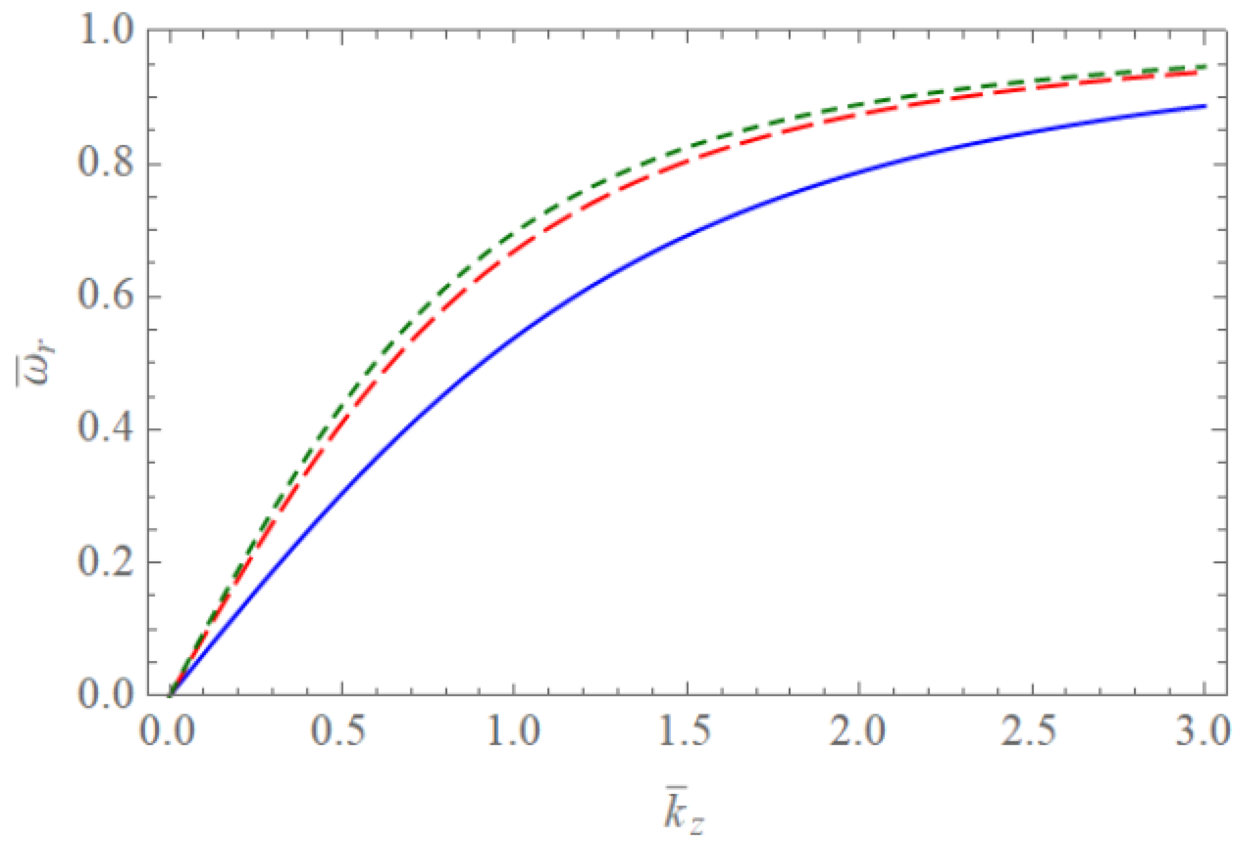
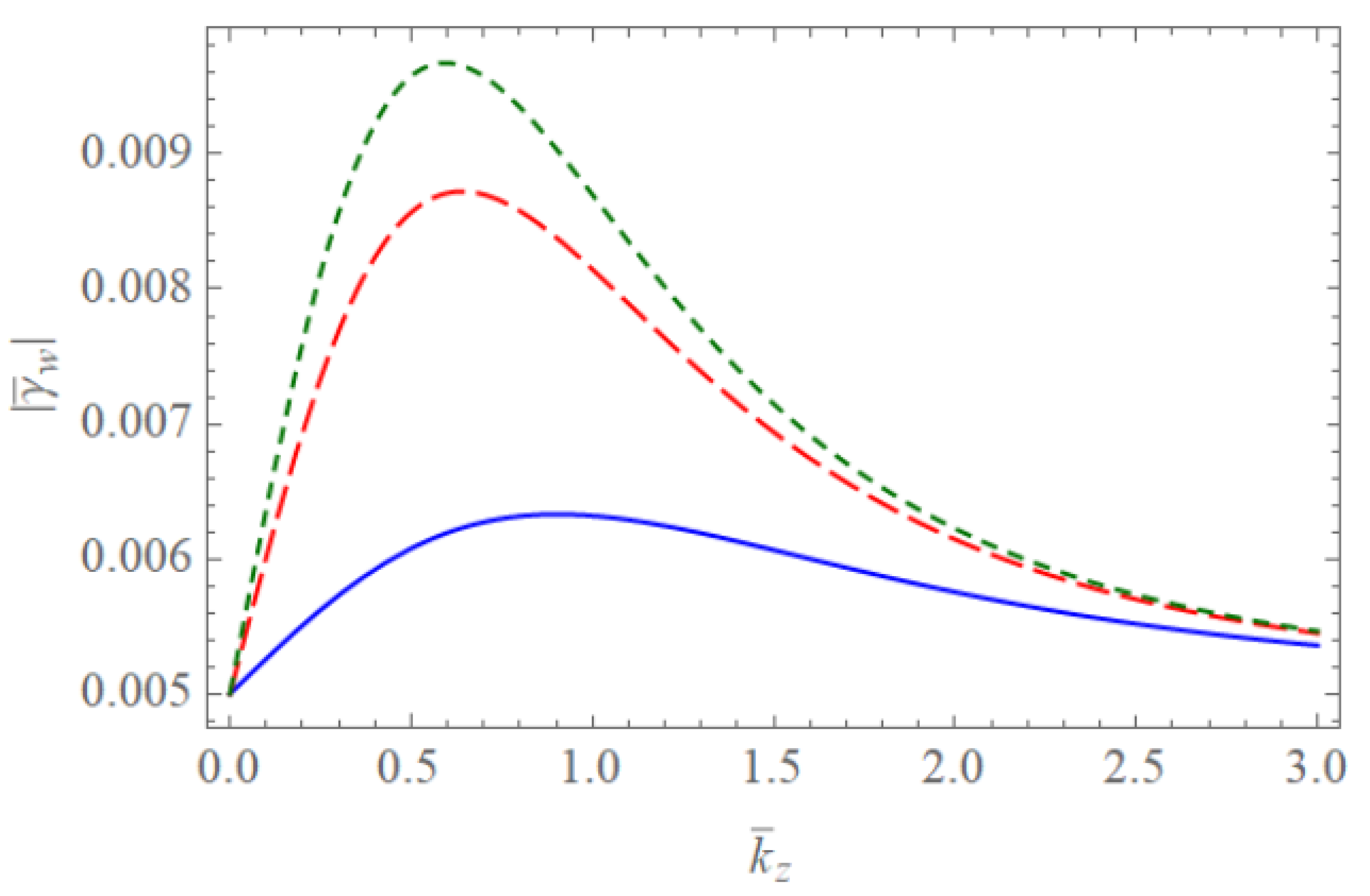
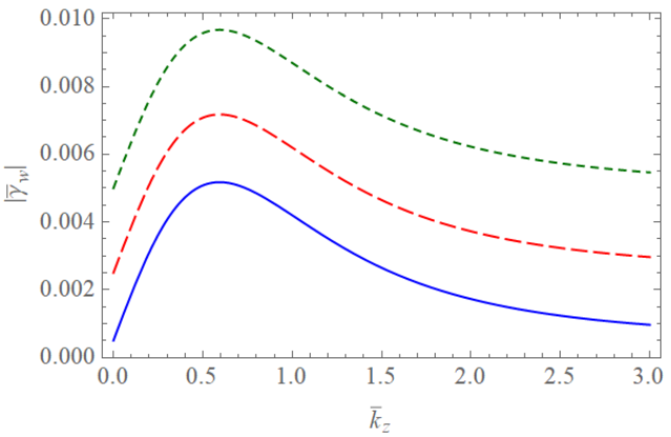
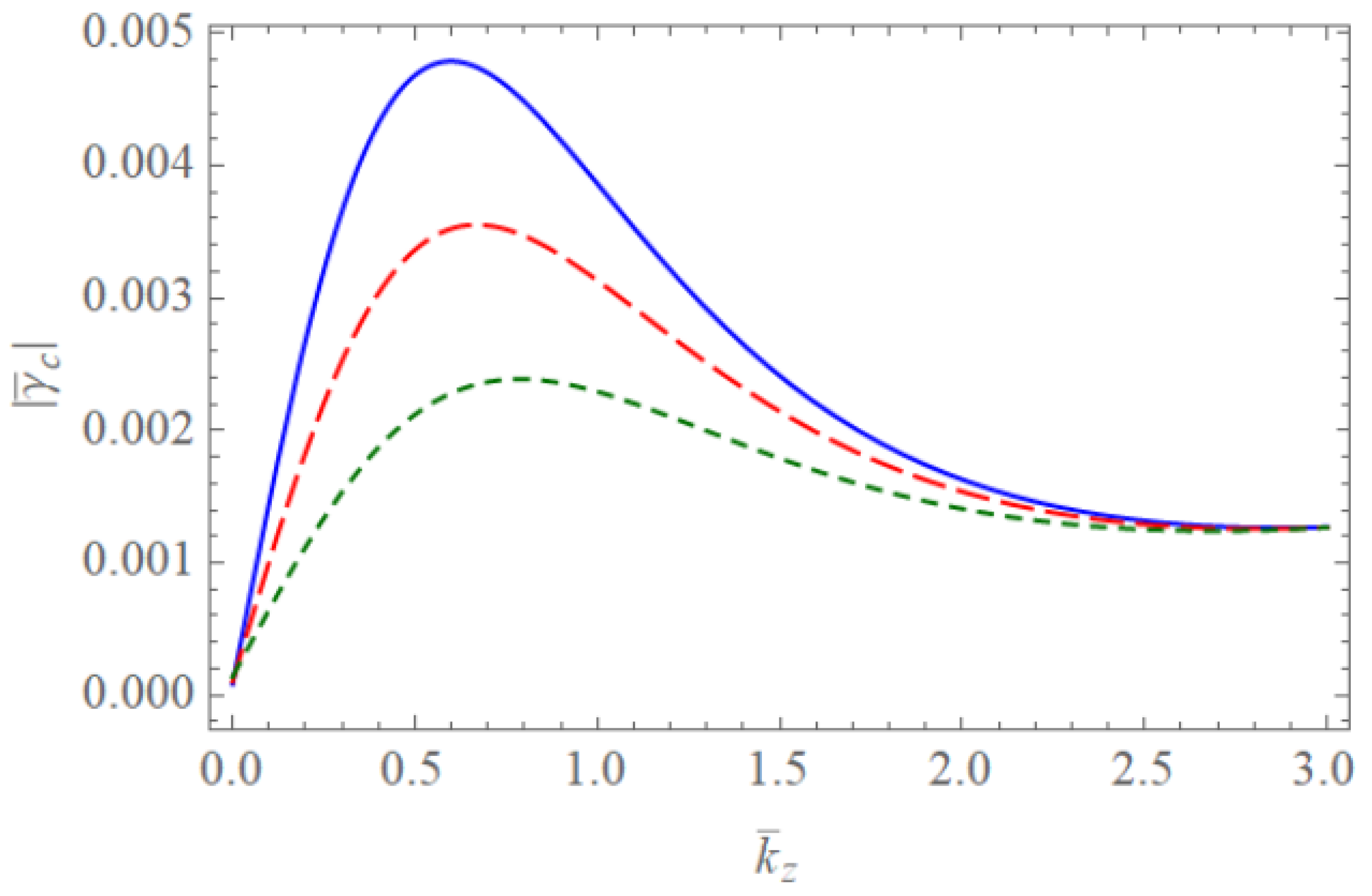
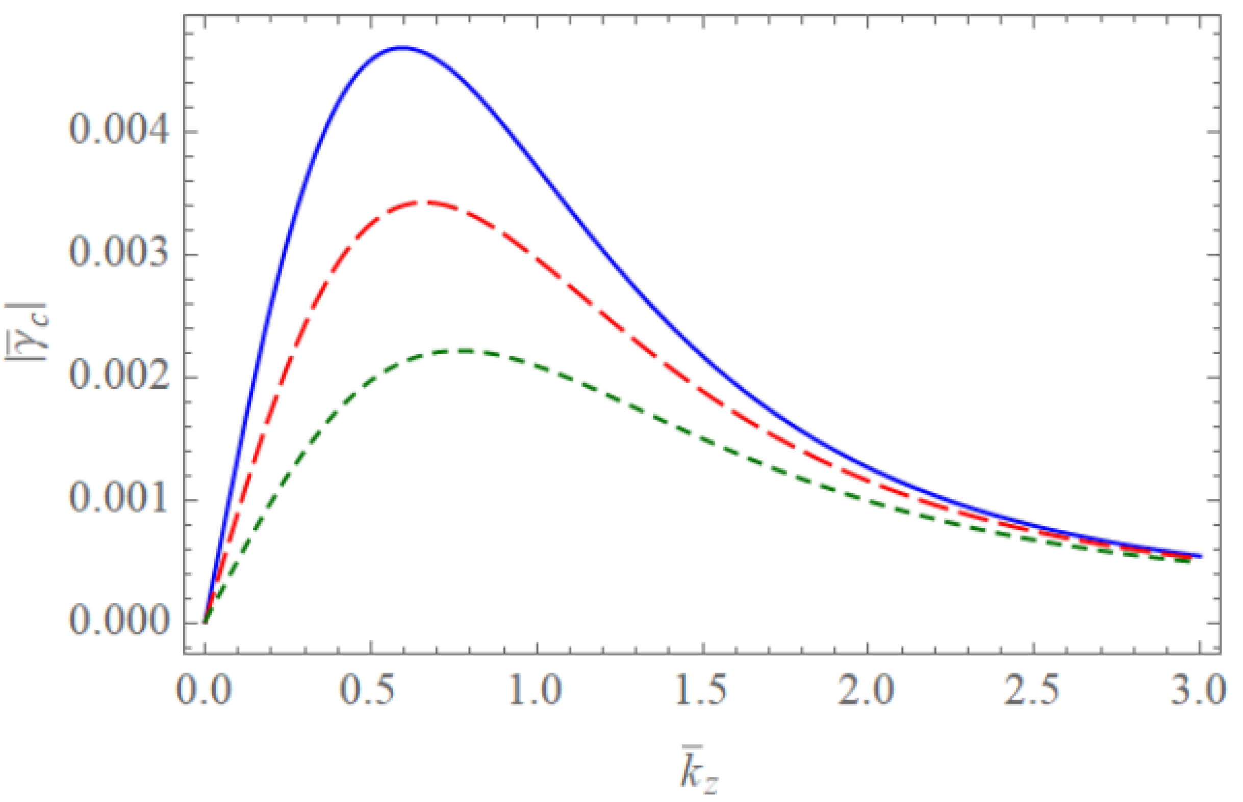
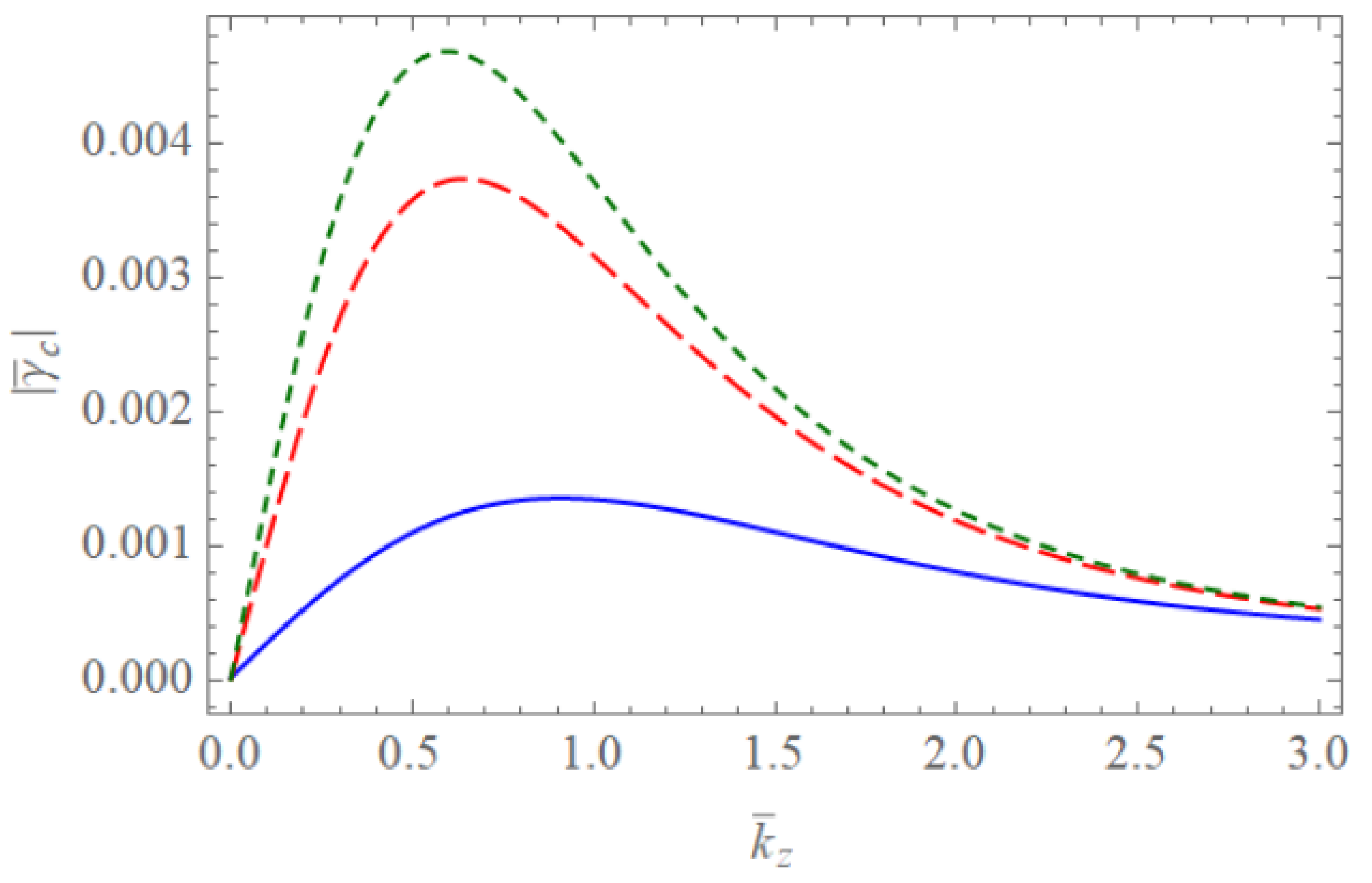
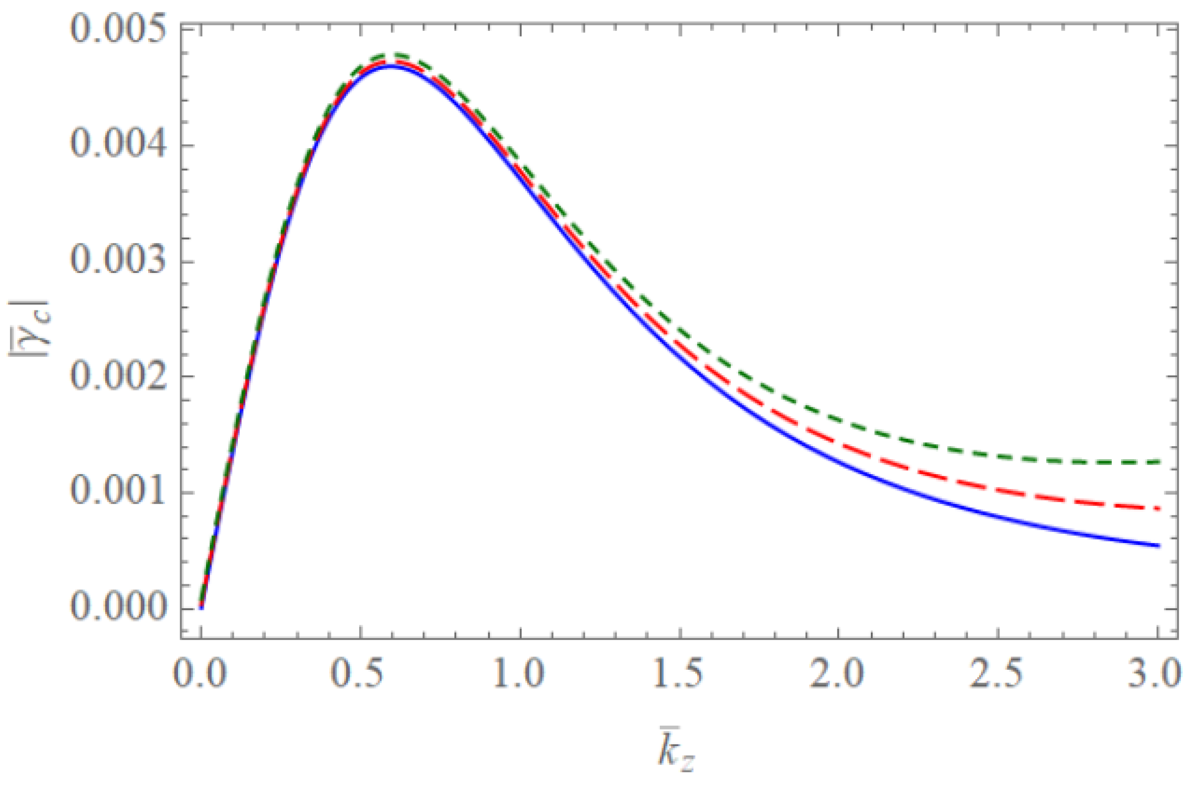
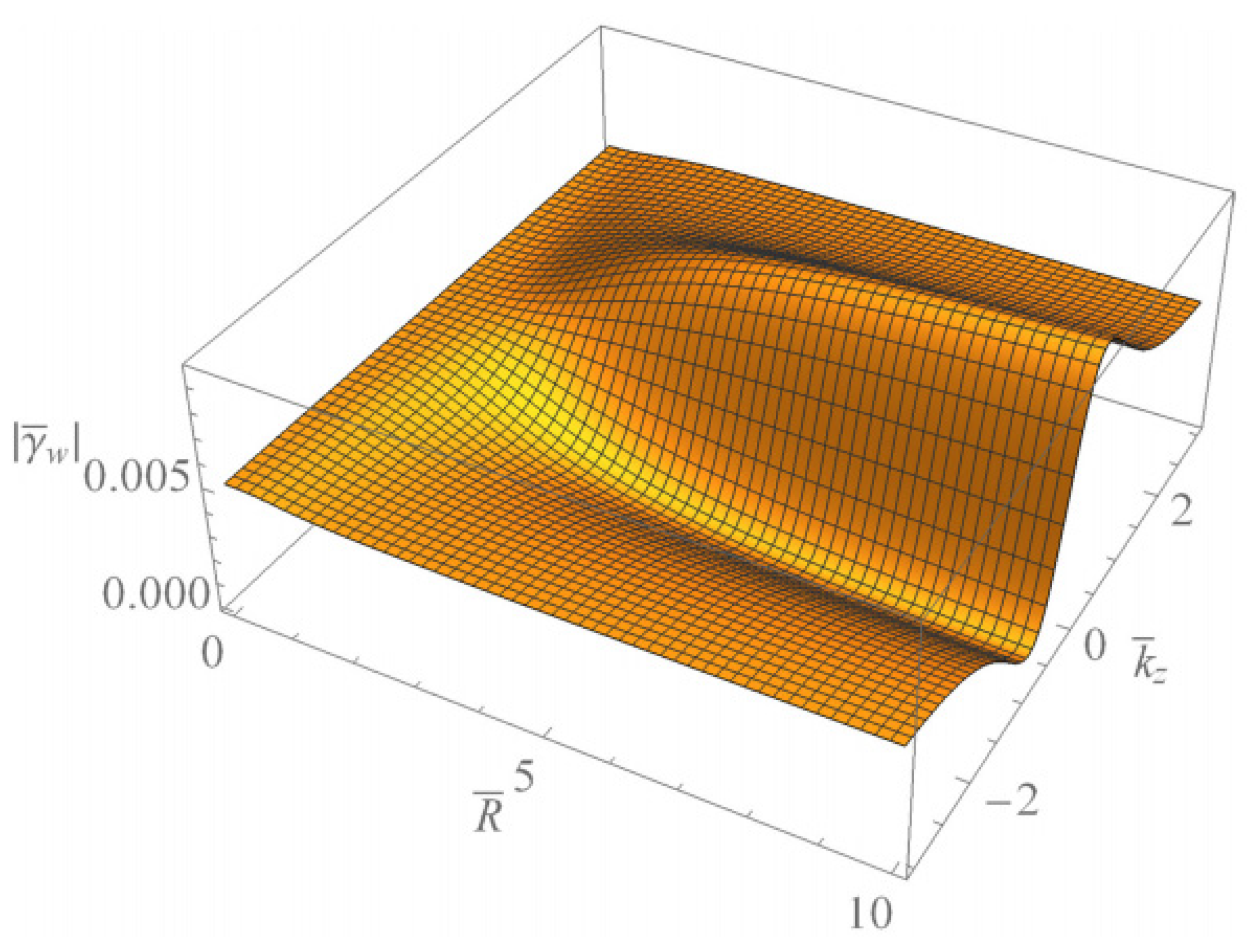
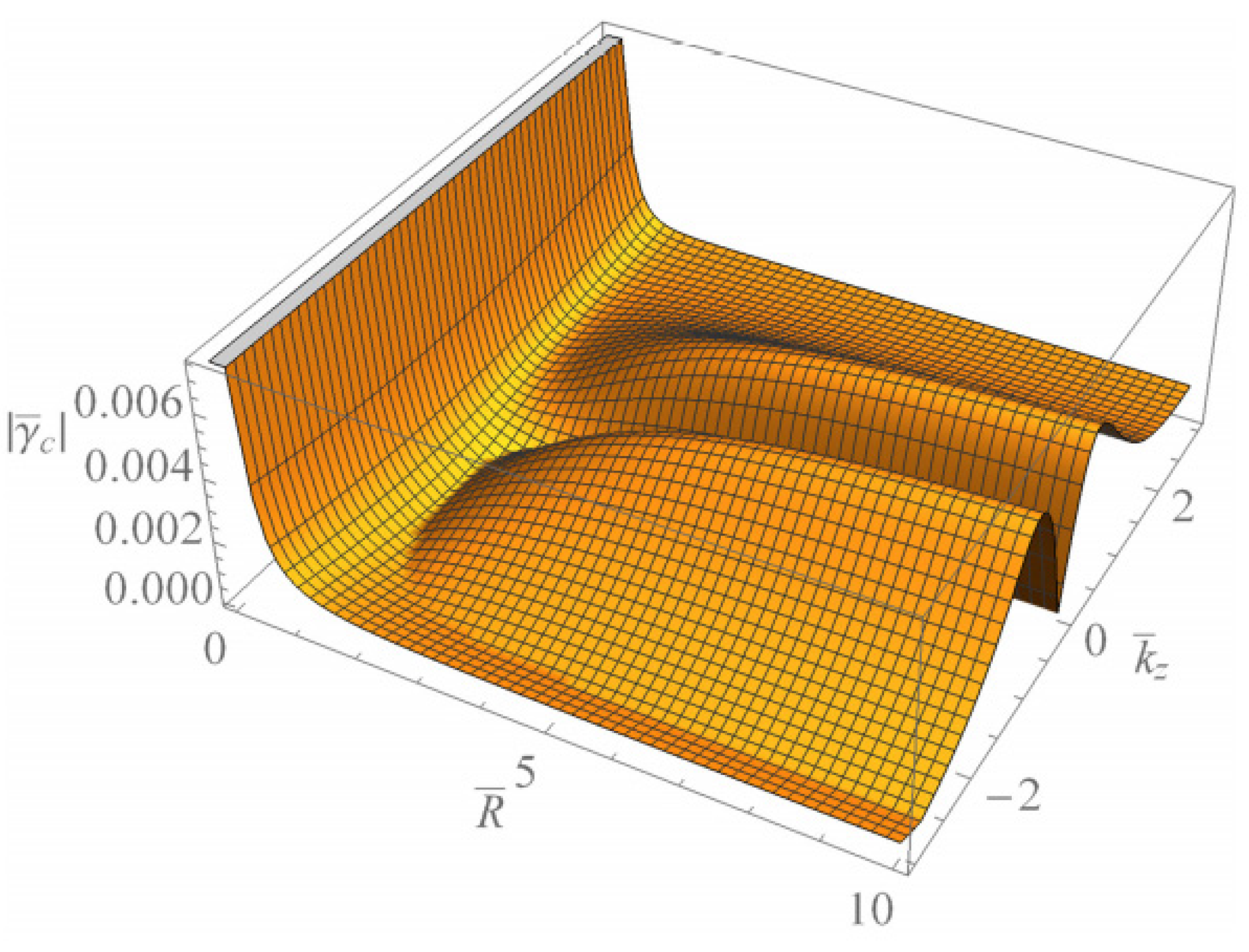
Figure 1 and Figure 2 show the scaled real frequencies ω ¯ r for weakly and completely ionized plasma waveguides as a function of k ¯ z for various values of the harmonic modes α 0 p when R ¯ = 10 and R ¯ = 2 , respectively. As we see in Figure 1 and Figure 2, the scaled real frequency ω ¯ r decreases with the harmonic number p for the Bessel eigenvalue α 0 p when R ¯ = 10 . However, it is interesting to note that the scaled real frequency ω ¯ r increases with the harmonic number p for the Bessel eigenvalue α 0 p when R ¯ = 2 . Hence, we have found that the dependence of the harmonic mode on the scaled real frequency ω ¯ r shows the opposite tendency for large and small radii of the cylindrical waveguide. Figure 3 and Figure 4 show the absolute values of the scaled damping rate | γ ¯ W | for weakly ionized plasma waveguides as a function of k ¯ z for various values of the harmonic modes α 0 p when R ¯ = 10 and R ¯ = 2 , respectively. As shown in Figure 3 and Figure 4, the scaled damping rate | γ ¯ W | decreases with the harmonic number p for the Bessel solution α 0 p when R ¯ = 10 . However, it is interesting to note the scaled damping rate | γ ¯ W | increases with the harmonic number p for the Bessel solution α 0 p when R ¯ = 2 . Hence, it is found that the dependence of the harmonic mode on the scaled damping rate | γ ¯ W | shows the opposite tendency for large and small radii of the cylindrical waveguide. Figure 5 represents the absolute value of the scaled damping rate | γ ¯ W | for weakly ionized plasma waveguides as a function of k ¯ z for various values of the ion-neutral collision frequency ν i n . As we can see from this figure, the scaled damping rate | γ ¯ W | increases with an increase of the collision frequency ν i n . Figure 6 and Figure 7 show the absolute values of the scaled damping rate | γ ¯ W | for the weakly ionized plasma waveguides as a function of k ¯ z for various values of the harmonic modes α 0 p when R ¯ = 10 and the temperature ratio are T i / T e = 0.01 and T i / T e = 0.001 , respectively. As shown in Figure 6 and Figure 7, the scaled damping rate | γ ¯ w | decreases with a decrease of the temperature ratio T i / T e . Hence, it is found that the scaled damping rate | γ ¯ w | for weakly ionized plasma waveguides decreases with an increase of the electron temperature. Figure 8 and Figure 9 show the absolute values of the scaled damping rate | γ ¯ C | for completely ionized plasma waveguides as a function of k ¯ z for various values of the harmonic modes α 0 p when R ¯ = 2 and the temperature ratio are T i / T e = 0.01 and T i / T e = 0.001 , respectively. As shown in Figure 8 and Figure 9, the scaled damping rate | γ ¯ C | decreases with a decrease of the temperature ratio T i / T e . Hence, the scaled damping rate | γ ¯ C | is found to decrease with an increase of the electron temperature. Figure 10 represents the absolute value of the scaled damping rate | γ ¯ C | for completely ionized plasma waveguides as a function of k ¯ z for various values of the ion-ion collision frequency ν i i . As we can see from this figure, the scaled damping rate | γ ¯ C | increases with an increase of the collision frequency ν i i . In addition, it is shown that the influence of the collision frequency ν i i is found to be more significant when k ¯ z > 1 . Figure 11 represents the surface profile of the absolute value of the scaled damping rate | γ ¯ W | for weakly ionized plasma waveguides as a function of R ¯ and k ¯ z . As we can see from this figure, the dependence of the wave number on the scaled damping rate | γ ¯ W | is getting more significant as an increase of the scaled radius R ¯ of the waveguide. It is interesting to note that the scaled damping rate | γ ¯ W | for weakly ionized plasmas shows the anti-symmetric behavior when the Trivelpiece–Gould wave propagates in the negative-z direction. Figure 12 represents the surface plot of the absolute value of the scaled damping rate | γ ¯ C | for completely ionized plasma waveguides as a function of R ¯ and k ¯ z . As we can see from this figure, the dependence of the wave number on | γ ¯ C | is getting more significant as the scaled radius R ¯ increases. We should note that | γ ¯ C | for completely ionized plasmas shows symmetric behavior when the Trivelpiece–Gould wave propagates in the negative-z direction. Hence, it is quite important to note that the mirror-reflection behavior of the scaled damping rate shows the opposite tendency for weakly and completely ionized plasmas.

5. Summary

In this work, we investigated the influence of ion collisions on the low-frequency ion-acoustic Trivelpiece–Gould wave in weakly and completely ionized plasma waveguides by using the method of normal modes and the separation of variables. Trivelpiece–Gould waves contain many advantages over bulk waves since they can produce plasmas with more spatially confined uniform density profiles, resulting in a wide range of applications. Since the collision frequency is not often small under experimental conditions for plasma research, we should take into account the collision frequency for the dielectric permittivity of the plasma when the deviation of the experimental results from the theoretical prediction is evident. In weakly ionized plasma waveguides, the dependence of the harmonic modes on the absolute value of the scaled damping rate shows the opposite tendency for large and small radii of the cylindrical waveguide. The scaled damping rates for both weakly and completely ionized plasma waveguides also decrease with an increase of the electron temperature. It is interesting to find that the scaled damping rate for weakly ionized plasma waveguides shows the anti-symmetric behavior when the Trivelpiece–Gould wave propagates in the negative-z direction. However, it is found that the scaled damping rate for completely ionized plasma waveguides shows symmetric behavior when the Trivelpiece–Gould wave propagates in the negative-z direction. Hence, it is quite interesting to note that the mirror-reflection behavior of the scaled damping rate shows the opposite tendency for weakly and completely ionized plasma waveguides. From this work, we have found that the collision effects on the damping rates of the Trivelpiece–Gould waves play significant roles in weakly and completely ionized plasma waveguides. These results would provide useful information on the stability of the Trivelpiece–Gould waves in collisional plasma waveguides.

Author Contributions

Conceptualization, M.-J.L. and Y.-D.J.; Formal analysis, M.-J.L. and Y.-D.J.; Funding acquisition, M.-J.L.; Investigation, M.-J.L. and Y.-D.J.; Methodology, M.-J.L. and Y.-D.J.; Project administration, M.-J.L.; Resources, M.-J.L. and Y.-D.J.; Software, M.-J.L. and Y.-D.J.; Writing—original draft, M.-J.L. and Y.-D.J.; Writing—review & editing, M.-J.L. and Y.-D.J. All authors have read and agreed to the published version of the manuscript.

Funding

The work was supported by the National Research Foundation of Korea (NRF) grant funded by the Korean Government (NRF-2019R1A2C1003363).

Institutional Review Board Statement

Not applicable.

Informed Consent Statement

Not applicable.

Data Availability Statement

The data that support the findings of this study are available upon reasonable request from the authors.

Acknowledgments

The authors gratefully acknowledge N. Ashikawa for warm hospitality and useful discussions while visiting National Institute for Fusion Science (NIFS), Japan. This research was initiated while the authors were visiting NIFS as visiting professors.

Conflicts of Interest

The authors declare no conflict of interest.

References

  1. Kaw, P.K. Surface Waves on a Plasma Half-Space. Phys. Fluids 1970, 13, 1784–1790. [Google Scholar] [CrossRef]
  2. Gradov, O.; Stenflo, L. Linear theory of a cold bounded plasma. Phys. Rep. 1983, 94, 111–137. [Google Scholar] [CrossRef]
  3. Whitham, G.B. Linear and Nonlinear Waves; Wiley: New York, NY, USA, 1999; pp. 209–262. [Google Scholar]
  4. Davidson, R.C. Methods in Nonlinear Plasma Theory; Academic Press: New York, NY, USA, 1972; pp. 54–129. [Google Scholar]
  5. Alexandrov, A.F.; Bogdankevich, L.S.; Rukhadze, A.A. Principles of Plasma Electrodynamics; Springer: Berlin/Heidelberg, Germany, 1984; pp. 308–309. [Google Scholar]
  6. Lee, M.-J.; Jung, Y.-D. Ion-driven instabilities of surface dust ion-acoustic waves in bounded plasma devices. Plasma Sources Sci. Technol. 2018, 27, 025010. [Google Scholar] [CrossRef]
  7. Lee, M.-J.; Takahashi, K.; Jung, Y.-D. Unstable electrostatic surface waves in a turbulent plasma containing streaming ions: Transverse truncation approach. Plasma Sources Sci. Technol. 2019, 29, 015007. [Google Scholar] [CrossRef]
  8. Aliev, Y.M.; Schlüter, H.; Shivarova, A. Guided-Wave-Produced Plasmas; Springer: Berlin/Heidelberg, Germany, 2000; pp. 49–50. [Google Scholar]
  9. Miyamoto, K. Plasma Physics for Controlled Fusion; Springer: Berlin/Heidelberg, Germany, 2016; pp. 110–115. [Google Scholar]
  10. Hasegawa, A. Plasma Instabilities and Nonlinear Effects; Springer: Berlin/Heidelberg, Germany, 1975; pp. 99–106. [Google Scholar]
  11. Semenov, V.E.; Zharova, N.A.; Anderson, D.; Lisak, M.; Puech, J. Simulations of multipactor in circular waveguides. Phys. Plasmas 2010, 17, 123503. [Google Scholar] [CrossRef] [Green Version]
  12. Khalil, S.M.; Mousa, N.M. Dispersion characteristics of plasma-filled cylindrical waveguide. J. Theor. Appl. Phys. 2014, 8, 111. [Google Scholar] [CrossRef] [Green Version]
  13. Girka, I.O.; Girka, O.I.; Thumm, M. Azimuthal surface waves in cylindrical metal waveguides partially filled by magnetoactive plasma: Analysis of energy transfer. Phys. Plasmas 2020, 27, 062108. [Google Scholar] [CrossRef]
  14. Shokri, B.; Rukhadze, A.A. Electrodynamics of Conducting Dispersive Media; Springer: Cham, Switzerland, 2019; pp. 227–339. [Google Scholar]
  15. Krall, N.A.; Trivelpiece, A.W. Principles of Plasma Physics; McGraw-Hill: New York, NY, USA, 1973; pp. 173–175. [Google Scholar]
  16. Zhang, K.-Z.; Xue, J.-K. Streaming instability in bounded three-component quantum plasmas. Phys. Plasmas 2010, 17, 32113. [Google Scholar] [CrossRef]
  17. Lee, M.-J.; Jung, Y.-D. Characteristics of Nonthermal Dupree Diffusion on Space-Charge Wave in a Kappa Distribution Plasma Column with Turbulent Diffusion. Entropy 2020, 22, 257. [Google Scholar] [CrossRef] [PubMed] [Green Version]
  18. Wyld, H.W. Mathematical Methods for Physics; Perseus Books: Reading, UK, 1999; pp. 139–141. [Google Scholar]
  19. Ramazanov, T.S.; Dzhumagulova, K.N.; Gabdullin, M.T. Effective potentials for ion-ion and charge-atom interactions of dense semiclassical plasma. Phys. Plasmas 2010, 17, 42703. [Google Scholar] [CrossRef]
  20. Akbari-Moghanjoughi, M. Quantized plasmon excitations of electron gas in potential well. Phys. Plasmas 2019, 26, 012104. [Google Scholar] [CrossRef] [Green Version]
  21. Akbari-Moghanjoughi, M.; Eliasson, B.E. Quantum Faraday excitations in degenerate electron-ion plasma. Phys. Scr. 2019, 95, 045604. [Google Scholar] [CrossRef]
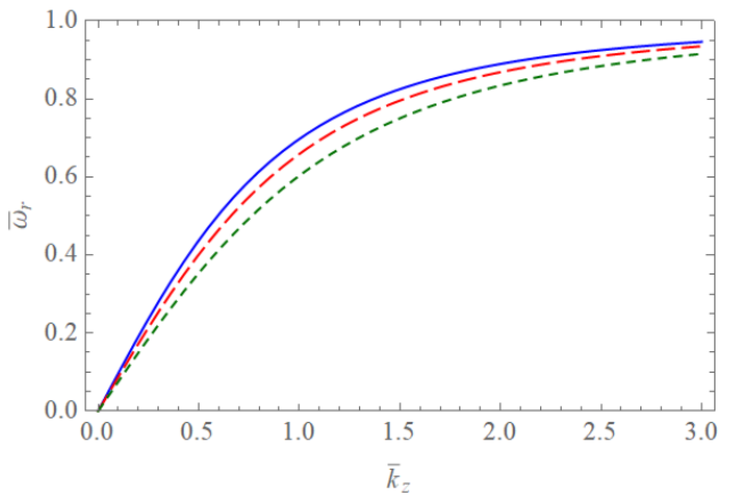
Figure 1. The scaled real frequency ω ¯ r of the Trivelpiece–Gould wave for weakly and completely ionized plasma waveguides as a function of k ¯ z when R ¯ = 10 . The blue solid line is the case of α 01 = 2.4048 . The red dashed line is the case of α 02 = 5.5201 . The green dotted line is the case of α 03 = 8.6537 .
Symmetry 13 00699 g001
Figure 2. The scaled real frequency ω ¯ r of the Trivelpiece–Gould wave for weakly and completely ionized plasma waveguides as a function of k ¯ z when R ¯ = 2 . The blue solid line is the case of α 01 = 2.4048 . The red dashed line is the case of α 02 = 5.5201 . The green dotted line is the case of α 03 = 8.6537 .
Symmetry 13 00699 g002
Figure 3. The absolute value of the scaled damping rate | γ ¯ W | of the Trivelpiece–Gould wave for weakly ionized plasma waveguides as a function of k ¯ z when R ¯ = 10 and ν ¯ i n = 0.01 . The blue solid line is the case of α 01 = 2.4048 . The red dashed line is the case of α 02 = 5.5201 . The green dotted line is the case of α 03 = 8.6537 .
Symmetry 13 00699 g003
Figure 4. The absolute value of the scaled damping rate | γ ¯ W | of the Trivelpiece–Gould wave for weakly ionized plasma waveguides as a function of k ¯ z when R ¯ = 2 and ν ¯ i n = 0.01 . The blue solid line is the case of α 01 = 2.4048 . The red dashed line is the case of α 02 = 5.5201 . The green dotted line is the case of α 03 = 8.6537 .
Symmetry 13 00699 g004
Figure 5. The absolute value of the scaled damping rate | γ ¯ W | of the Trivelpiece–Gould wave for weakly ionized plasma waveguides as a function of k ¯ z when R ¯ = 10 . with α 01 = 2.4048 . The blue dashed line is the case of ν ¯ i n = 0.01 . The red dotted line is the case of ν ¯ i n = 0.05 . The green dotted line is the case of ν ¯ i n = 0.01 .
Symmetry 13 00699 g005
Figure 6. The absolute value of the scaled damping rate | γ ¯ C | of the Trivelpiece–Gould wave for completely ionized plasma waveguides as a function of k ¯ z when R ¯ = 10 , ν ¯ i i = 0.01 , and T i / T e = 0.01 . The blue solid line is the case of α 01 = 2.4048 . The red dashed line is the case of α 02 = 5.5201 . The green dotted line is the case of α 03 = 8.6537 .
Symmetry 13 00699 g006
Figure 7. The absolute value of the scaled damping rate | γ ¯ C | of the Trivelpiece–Gould wave for completely ionized plasma waveguides as a function of k ¯ z when R ¯ = 10 , ν ¯ i i = 0.01 , and T i / T e = 0.001 . The blue solid line is the case of α 01 = 2.4048 . The red dashed line is the case of α 02 = 5.5201 . The green dotted line is the case of α 03 = 8.6537 .
Symmetry 13 00699 g007
Figure 8. The absolute value of the scaled damping rate | γ ¯ C | of the Trivelpiece–Gould wave for completely ionized plasma waveguides as a function of k ¯ z when ν ¯ i i = 0.01 and T i / T e = 0.01 with α 01 = 2.4048 . The blue solid line is the case of R ¯ = 2 . The red dashed line is the case of R ¯ = 5 . The green dotted line is the case of R ¯ = 10 .
Symmetry 13 00699 g008
Figure 9. The absolute value of the scaled damping rate | γ ¯ C | of the Trivelpiece–Gould wave for completely ionized plasma waveguides as a function of k ¯ z when ν ¯ i i = 0.01 and T i / T e = 0.001 with α 01 = 2.4048 . The blue solid line is the case of R ¯ = 2 . The red dashed line is the case of R ¯ = 5 . The green dotted line is the case of R ¯ = 10 .
Symmetry 13 00699 g009
Figure 10. The absolute value of the scaled damping rate | γ ¯ C | of the Trivelpiece–Gould wave for completely ionized plasma waveguides as a function of k ¯ z when R ¯ = 10 with α 01 = 2.4048 . The blue solid line is the case of ν ¯ i i = 0.001 . The red dashed line is the case of T i / T e = 0.005 . The green solid line is the case of ν ¯ i i = 0.01 .
Symmetry 13 00699 g010
Figure 11. The surface plot of the absolute value of the scaled damping rate | γ ¯ W | of the Trivelpiece–Gould wave for weakly ionized plasma waveguides as a function of R ¯ and k ¯ z when ν ¯ i n = 0.01 with α 01 = 2.4048 .
Symmetry 13 00699 g011
Figure 12. The surface plot of the absolute value of the scaled damping rate | γ ¯ C | of the Trivelpiece–Gould wave for completely ionized plasma waveguides as a function of R ¯ and k ¯ z when ν ¯ i n = 0.01 and T i / T e = 0.01 with α 01 = 2.4048 .
Symmetry 13 00699 g012
Publisher’s Note: MDPI stays neutral with regard to jurisdictional claims in published maps and institutional affiliations.