Article

Path Tracking of Permanent Magnet Synchronous Motor Using Fractional Order Fuzzy PID Controller

1
School of Control Science and Engineering, Dalian University of Technology, Dalian 116023, China
2
School of Electronics and Information Engineering, Dalian Jiaotong University, Dalian 116028, China
*
Author to whom correspondence should be addressed.
Symmetry 2021, 13(7), 1118; https://doi.org/10.3390/sym13071118
Submission received: 25 May 2021 / Revised: 13 June 2021 / Accepted: 16 June 2021 / Published: 23 June 2021

Abstract

:
Permanent magnet synchronous motor (PMSM) AC servo system has the characteristics of uncertainty, time-varying, nonlinear and fractional order. Applying the traditional control method is difficult to achieve the desired control effect. The fuzzy control has strong adaptability to the parameter change, nonlinearity and imprecise model of the controlled object. The simulation model of permanent magnet synchronous motor three closed-loop systems is established. The control principle and the realization of space vector pulse width modulation (SVPWM) are studied by using a vector control strategy. Due to the fractional-order characteristic of the motor, a fuzzy logic algorithm is used to realize the parameter self-tuning of the fractional-order proportional integral differential (PID) controller. The controller is selected as the position regulator of the servo motor. It combines the precision of fractional-order PID controller with the adaptability of fuzzy control and adds feed-forward to improve the response speed. The path tracking experiments on several different paths are carried out, and the results show that the control method is effective and can meet the trajectory tracking requirements of servo control. Finally, the speed and position tracking test of the PMSM AC servo system is carried out on the test verification platform, which verifies the effectiveness of the control algorithm.

1. Introduction

The existing systems are affected by non-integer-order, especially the dynamic processes of large-scale diffusion or heat conduction with memory and heredity. The research proves that the actual capacitance and inductance are fractional in nature [1]. Permanent magnet synchronous motor (PMSM) is widely used as a controlled object in small and medium capacity servo control systems because of its simple physical structure, small installation space, low torque ripple and high efficiency. PMSM has the characteristics of strong coupling, non-linearity and fractional-order, which makes the PMSM servo system also show some such characteristics [2,3]. Generally, only an approximate mathematical model can be established. The traditional PI controller needs to establish an accurate mathematical model of the controlled object, which is often difficult to achieve the desired control effect. The fuzzy controller represents the experience of experts or operators with the control algorithm that can be realized by computer. It has strong adaptability to the parameter variation, non-linearity and model inaccuracy of the control object.
Considering the control performance index, the PMSM control strategy needs to achieve the goals of small current harmonic component, fast speed response and high steady-state accuracy. Liu [4] changed the traditional position, speed and current three-loop control from structure to position-current double-loop control and proposed a control strategy based on active disturbance rejection controller (ADRC), which simplified the debugging process. Zuo [5] synthesized the position and speed controllers into the outer loop controllers of the system. An integrated design method of position and speed based on second-order auto-disturbance rejection was proposed, which not only retained the advantages of auto-disturbance rejection control but also solved the problem of uncontrollable speed. The precise positioning of the servo system was realized. In view of the strong coupling, slow time-varying and uncertain disturbances in high-power AC servo system, Hou [6,7] respectively combined the fuzzy method with self-wavelet sliding mode control and wavelet neural network to design an adaptive control method; Zhang [8] considered the external disturbance when the manipulator was working, designed a disturbance observer based on the non-singular terminal sliding mode to realize the external disturbance. The input of the system is estimated and compensated.
However, previous studies mostly focus on integer-order systems, ignoring the fractional-order characteristics of the motor, and the robustness of the designed system needs to be further improved. Zhang et al. [9] proposed a fractional sliding mode control scheme based on self-tuning of fuzzy parameters, which is robust to external load disturbance and parameter change in speed control of permanent magnet synchronous motor. Sun et al. [10] proposed an adaptive fractional-order (FO) terminal sliding mode control (SMC) strategy for linear motor tracking control, which is like the traditional fast nonsingular matrix control method. By comparison, the proposed method has a feed-forward integral sliding surface and adaptive switching input and achieves higher convergence accuracy in the presence of system uncertainties in the motion control system. Yue [11] applies fractional-order PID control algorithm to direct torque control (DTC) scheme and combines it with support vector machine pulse width modulation (SVPWM) to improve the dynamic performance and anti-interference ability of PMSM speed control. Xie [12] presents a data-driven Adaptive Fractional Order proportional integration (AFOPI) control method. The closed-loop process data are used to design AFOPI controllers with unknown noise distribution and data loss probability. The convergence and stability of the algorithm are verified. A robust fractional proportional derivative (FOPD) controller is proposed, which acts on the action function (AF), and a fuzzy logic inference algorithm is designed to obtain the parameters of AF [13]. A novel Hybrid Differential Artificial Bee Colony Algorithm (HDABCA) has been proposed for designing a fractional-order proportional-integral (FO-PI) speed controller in a Permanent Magnet Synchronous Motor (PMSM) drive [14]. An adaptive controller is proposed to suppress the chaotic oscillation of the fractional-order model, and the control problem of three-dimensional nonautonomous fractional-order uncertain model and the chaotic behavior of the fractional-order calculus system are studied [15]. A new adaptive control strategy, fuzzy integral sliding mode control scheme is proposed, and a new sliding surface of the fraction is designed, which solves the stability of the wind power conversion system of PMSM [16]. A new three mode sliding mode controller is proposed, which can suppress the influence of noise feedback on nonlinear systems with noise and uncertainty [17].
In recent years, fractional-order fuzzy systems and fractional-order fuzzy control have attracted extensive attention from scholars in China and foreign countries. Combining fuzzy control with fractional sliding mode control, Delavari H. et al. [18] studied the design of fuzzy fractional sliding mode controller for integer-order nonlinear systems. Lin et al. [19] introduced the adaptive fuzzy control method into fractional-order chaotic systems H synchronization problem. However, due to the problems in the process of calculating the fractional derivative of the energy function, an Iranian scholar commented on and revised part of the paper [20]. Based on the integer-order T-S fuzzy model and LMI square, Zhong et al. [21] studied the impulse control problem of fractional-order chaotic systems. The above literature was concerned with the concepts of fuzzy systems and fuzzy control when dealing with fractional-order system problems.
In this paper, PMSM is taken as the object. Firstly, the structure and mathematical model of PMSM are studied, and the SVPWM control technology is selected to study the fractional order PID controller. The self-tuning fractional-order PID controller with fuzzy parameters is designed to realize the self-tuning of the three parameters: proportion, integral and integral order. The simulation model is established, and the fuzzy fractional-order PID is compared with the traditional PID controller. The simulation results show that the design is effective, achieves the desired control performance, responds faster and has higher precision. Finally, according to the actual trajectory characteristics, speed feed-forward and acceleration feed-forward are added to verify the effectiveness of the composite control method.
The paper is organized as follows: In Section 2, the structure and mathematical model of Permanent Magnet Synchronous Motor Control System are given. In Section 3 fractional-order operator, fractional-order system and fractional-order PI controller are described. And fuzzy parameter self-tuning controller is designed. Simulation research and result analysis is carried in Section 4. Experiment and test is carried in Section 5, and conclusions are drawn in Section 6.

2. Permanent Magnet Synchronous Motor Control System

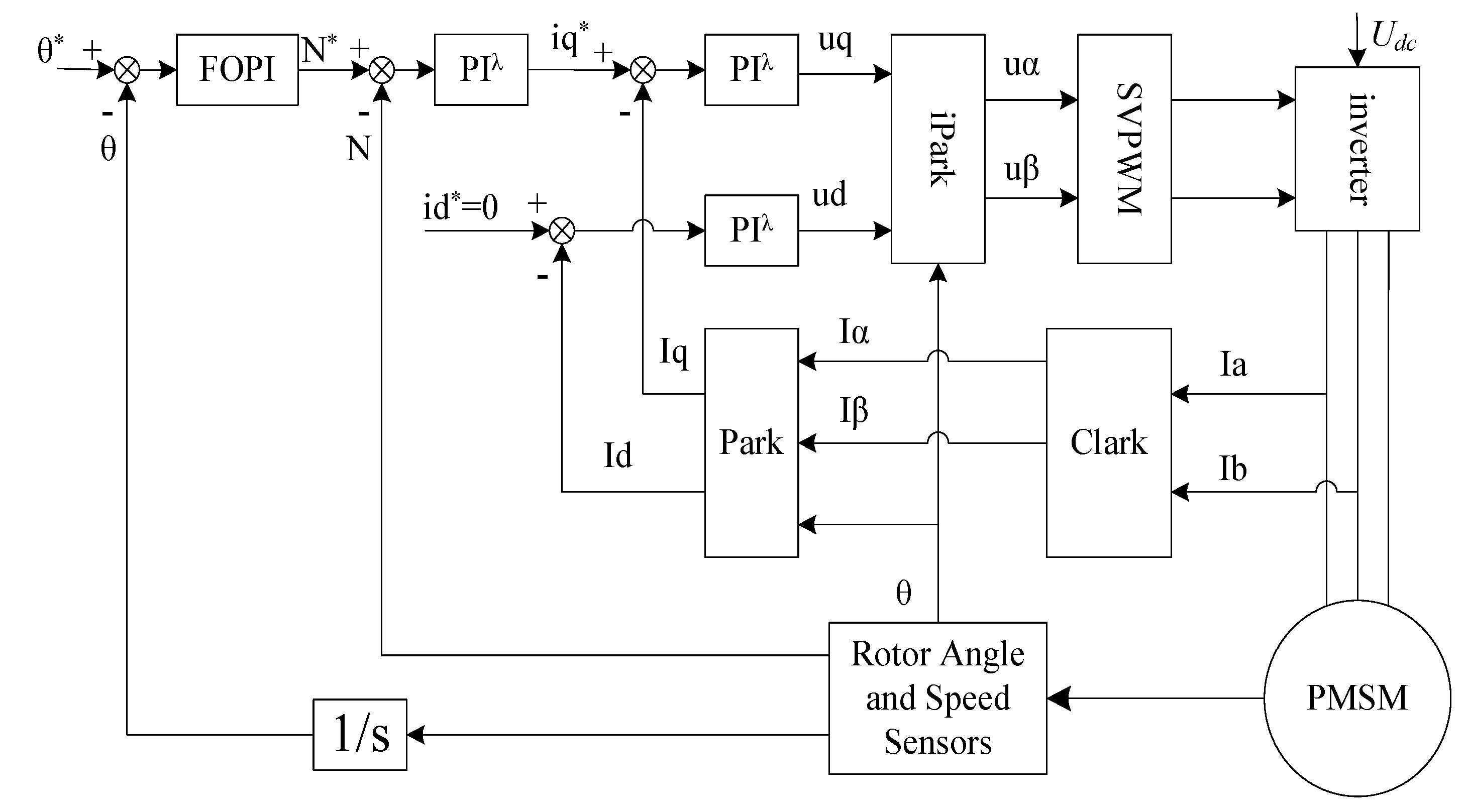
2.1. PMSM AC Servo Control System

The control principle diagram of three closed-loop PMSM AC servo control systems is shown in Figure 1. The fractional PIλ regulator realizes the control of the current loop and speed loop, and the fractional PIλ controller realizes the control of the position loop based on the parameter self-tuning of fuzzy logic.
The speed loop can enhance the anti-load disturbance and robustness of the servo system. The component of the torque and current generated by the output of the speed loop is the given value of the current loop. The output of the current loop directly affects the drive of the inverter to the motor, and the setting of the parameters of the current loop directly affects the control accuracy and response speed of the system. The PMSM AC servo system requires a current loop to satisfy the performance of a small harmonic component of output current and fast response speed. The current regulator needs to satisfy the response speed of inner loop control. The function of the position loop regulator is to ensure the static accuracy and dynamic tracking performance of the system.
For a permanent magnet synchronous motor servo system, in addition to its fast dynamic response and stable steady-state operation, it also requires that the system can achieve accurate positioning and fast-tracking. Position controller directly affects the positioning control and position tracking performance of the system. Position servo system requires fast dynamic response, no overshoot and high steady-state accuracy. The traditional PID controller has a simple structure and strong robustness. Due to the linear combination of three components in itself, it is difficult to balance the static performance and dynamic performance of the controller, and the tracking setting value and the ability to suppress disturbance; moreover, due to some uncertain factors in the system, such as the non-linearity of the characteristics of the control object. The time-varying parameters and disturbance factors require the speed controller to have strong adaptive ability (fast-tracking when the speed deviation is large, smooth operation and accurate positioning without error when the speed deviation is small).

2.2. Mathematical Model of Permanent Magnet Synchronous Motor

Before discussing the mathematical model of permanent magnet synchronous motor, it is considered that the stator and rotor of the motor have a smooth surface, ignoring the core magnetic saturation, eddy current and hysteresis loss, the conductivity of permanent magnet material is zero, the stator is three-phase symmetrical, the rotor has no damping winding and is symmetrical in structure, and the induced electromotive force waveform in the three-phase winding is sinusoidal.
The circuit equation of the mathematical model based on the rotor rotation coordinate system d-q is as follows:
{ d d t i d = 1 L d U d R L d i d + L q L d ω r i q d d t i q = 1 L q U q R L q i q + L d L q ω r i d λ 0 ω r L q
where: Ld and Lq are the inductors on d and q axis, respectively; R is the internal resistance of stator; id and iq are the current components on d and q axis, respectively; Ud and Uq are the voltage components on d and q axis, respectively; ωr is the angular speed of rotor; λ0 is the electromagnetic torque coefficient.
The torque equation is as follows:
T e = 3 2 p n [ ψ f i q ( L d L q ) i d i q ]
The equation of motion is as follows:
T e T L = J d ω r d t
Among them, Te is the electromagnetic torque, TL is the motor torque, J is the moment of inertia, pn is the pole pairs of the rotor, Ψf is the flux produced by the permanent magnet.

2.3. Vector Control of Permanent Magnet Synchronous Motor

The vector control strategy was first used to deal with the speed regulation of an AC motor with high-performance motor control, and its control effect is similar to that of a DC motor. The coordinate transformation of an AC motor is needed, that is, from a three-phase stator ABC coordinate system of an AC motor to a two-phase rotor d-q coordinate system that can be controlled by DC motor, and then the control quantity is obtained by DC motor control theory. In order to control the AC motor by Inverse Coordinate transformation, the SVPWM method is adopted to control the three-phase power supply of the motor.
According to the calculation steps of the SVPWM algorithm and module building method [22], the structure diagram of the space vector pulse width modulation algorithm is established as shown in Figure 2. Sector judgment module sub1_N determines the sector where the vector is located, adjacent action time module sub1_XYZ determines the action time of adjacent two vectors, T1 and T2 generation module sub1_T1T2 simulates the action time ratio of adjacent vectors, vector switching point realization module sub1_Tcm determines the switching point of the comparator, and SVPWM waveform generation module sub1_PWM generates six PWM waves.

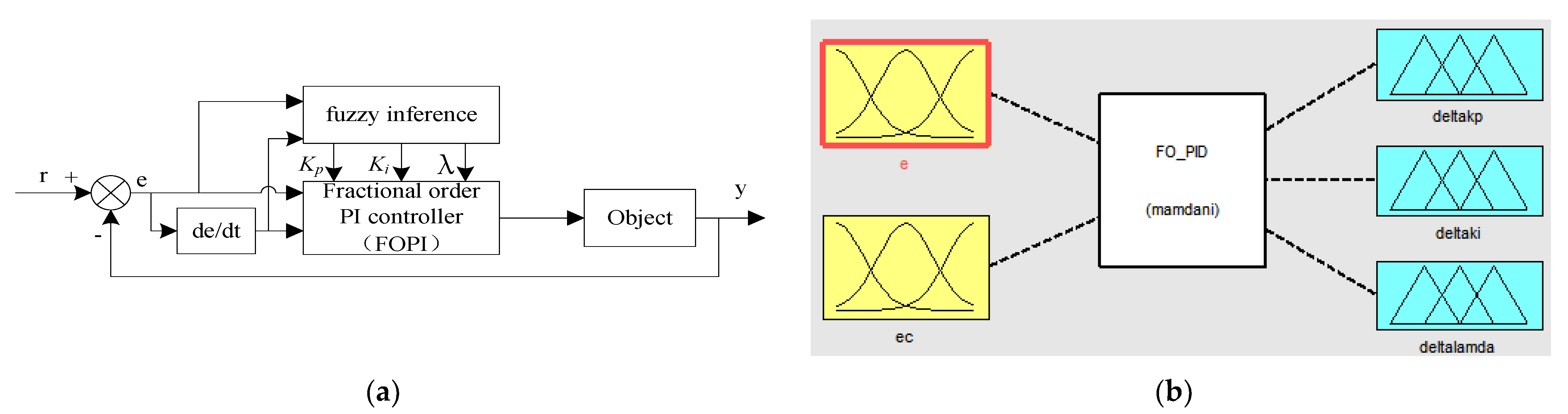
2.4. Fuzzy PIλ Position Control (FOPI)

Fuzzy fractional PIλ controller combines fuzzy control with fractional PIλ control. According to the actual operation, the parameters are self-tuned online according to the rules of parameter adjustment. The position controller consists of two parts, i.e., fractional PIλ control part and parameter setting part of fuzzy reasoning. Its structure is shown in Figure 3.

3. Fuzzy Parameter Self-Tuning PIλ Controller

3.1. Fractional-Order Operator

Fractional calculus is essentially a non-integer-order calculus, or any order calculus, the order number can be real or even a complex number. The basic operation of fractional calculus is D t α a [23], it can be defined as
D t α a = { d α d t α , R ( α ) > 0 1 , R ( α ) = 0 a t ( d τ ) ( α ) , R ( α ) < 0
where α and t are the upper and lower bounds of the operators, α is the order, which can be any complex number, assuming a real number in the paper. Where R ( α ) is the real part of α.
There are several famous definitions for fractional derivatives. Among them, the most frequently used definitions are Riemann–Liouville definition and Caputo definition [23].
The fractional-order differ-integral operator satisfies the exchange law and the superposition principle [24]
D α ( D β f ( t ) ) = D β ( D α f ( t ) ) = D α + β f ( t )

3.2. Fractional-Order System

The fractional-order system is the object model based on a fractional differential equation. Some basic theory of fractional differential equations is also the basis of fractional-order systems. The general form of the fractional-order linear differential equation:
a n D α n f + + a 1 D α 1 f + a 0 D α 0 f = b D m β m g + + b 1 D β 1 g + b 0 D β 0 g
where, f = f ( x , y ) and g = g ( x , y ) are the functions of variables X and Y, which is the output and input respectively. The value of a i and b j are real number, a i (i = 0, 1, …, n) and b j (j = 0, 1, …, m) can be fractional or decimal, and meet the conditions α n > α n 1 > > α 1 > α 0 and β m > β m 1 > > β 1 > β 0 .
For zero initial conditions, Equation (6) is transformed into Equation (7) by applying the Laplace transform.
G ( s ) = b m s β m + b m 1 s β m 1 + + b 0 s β 0 a n s α n + a n 1 s α n 1 + a 0 s α 0
The fractional-order system identification methods include two kinds of time domain method and frequency domain method. In recent years, the intelligent optimization method is applied to the identification of fractional-order systems.
Oustaloup’s approximation method uses a band-pass filter to approximate the fractional-order operator s λ based on frequency domain response. The approximate transfer function of a continuous fractional-order operator s λ with Oustaloup’s Algorithm is as follows [25]:
G f ( s ) = K k = N N s + ω k s + ω k
where the zeros, poles and the gain can be evaluated, respectively, as:
ω k = ω b ( ω h ω b ) k + N + 1 2 ( 1 λ ) 2 N + 1
ω k = ω b ( ω h ω b ) k + N + 1 2 ( 1 + λ ) 2 N + 1
K = ( ω h ω b ) λ 2 k = N N ω k ω k
In our simulation, for approximation of s λ , the frequency range is closed as: ω [ ω b , ω h ] and ω b = 0.001 , ω h = 1000 , N = 4.

3.3. Fractional-Order PI Controller (PIλ)

The fractional-order PID controller is a generalization of the traditional PID controller. Differential control is not usually used for permanent magnet synchronous motor control, so the transfer function of the PI lambda controller [26] is as follows:
G c ( s ) = k p + k i s λ ( λ > 0 )
where s = j ω is complex frequency, kp is proportional constant, ki is integral constant, and λ is the order of an integral part. Let the transfer function of the controller object be P(s). Using the plant object and FOC transfer function (12), the transfer function of the open-loop system is expressed as
G ( s ) = G c ( s ) P ( s )
In the case of FOC design, the system fulfills different requirements as robustness to load disturbances, uncertainties and high-frequency noise of the plant are concerned. Therefore, gain margin and phase margin, robustness to parameter variation and sensitivity function are considered in the system design. Based on the basic definitions of phase margin and gain crossover frequency, the controller must satisfy the following constraints [27,28,29].
Phase margin constraint:
A r g ( G ( j ω ) ) ω = ω c = A r g ( G c ( j ω ) P ( j ω ) ) = π + ϕ m
where P() is the transfer function of the plant, G() is the transfer function of the open-loop system, Gc() is the transfer function of the controller, ω is the gain crossover frequency, and ϕm is the required phase margin.
Gain crossover frequency constraint:
| G ( j ω ) | d B = | G c ( j ω ) P ( j ω ) | d B = 0
where dB is the unit of amplitude in amplitude-frequency characteristics. Robustness to parameter changes:
For specific ω, the Bode diagram is smooth. The system is considered to be more robust to gain variation and overshoot of step input response. Therefore, the controller can satisfy this condition:
| d ( A r g ( G ( j ω ) ) ) d ω | ω = ω c = 0
Interference suppression: The constraint related output interference cancellation sensitive function S can be as follows
| S ( j ω ) = 1 1 + G c ( j ω ) P ( j ω ) | d B M ( d B ) ω ω s r a d / s | S ( j ω s ) | d B = M ( d B )
where M is the preferred value of the sensitivity function for frequencies ω ω s rad/s.
Consider using the fuzzy logic algorithm to adjust the parameters in Equation (12). The proportional coefficient kp, integral coefficient ki and integral order λ are determined by the following items:
k p = k p 0 ( 1 + α { E , E C } P )
k i = k i 0 ( 1 + β { E , E C } I )
λ = λ 0 + γ { E , E C } λ
Among them, {E,EC}P, {E,EC}I, {E,EC}λ are the results of fuzzy reasoning. kp0, ki0 and λ0 are the initial values of the parameters, respectively. α , β and γ are used as adjustment factors, and a particle swarm optimization algorithm is used to find the optimal solution [24]. As for the determination of the initial value, the requirement of self-adjusting controller parameters for the initial value is not high. Due to the robustness of PID control and the flexibility of fuzzy control, the conventional PID method can be used to control the system first, without requiring that all performance indicators of the system meet the requirements. If the system reaches a stable state, these parameters can be used as the initial value of PIλ parameter adjustment. Then the PIλ parameters are fine-tuned on-line by using fuzzy control, so that the system performance index can meet the requirements [30,31,32,33,34].

3.4. Design of Fuzzy Parameter Self-Tuning Controller

A fuzzy parameter self-tuning PIλ controller is designed. Based on fractional-order PI controller (FOPI), the parameters kp, ki and λ of fractional order PI controller are tuned online according to the idea of fuzzy reasoning, taking the deviation E and deviation change rate EC of feedback value and given value of the controlled object as input, in order to meet the need of control accuracy of different control systems. The fuzzy controller has two inputs and three outputs.

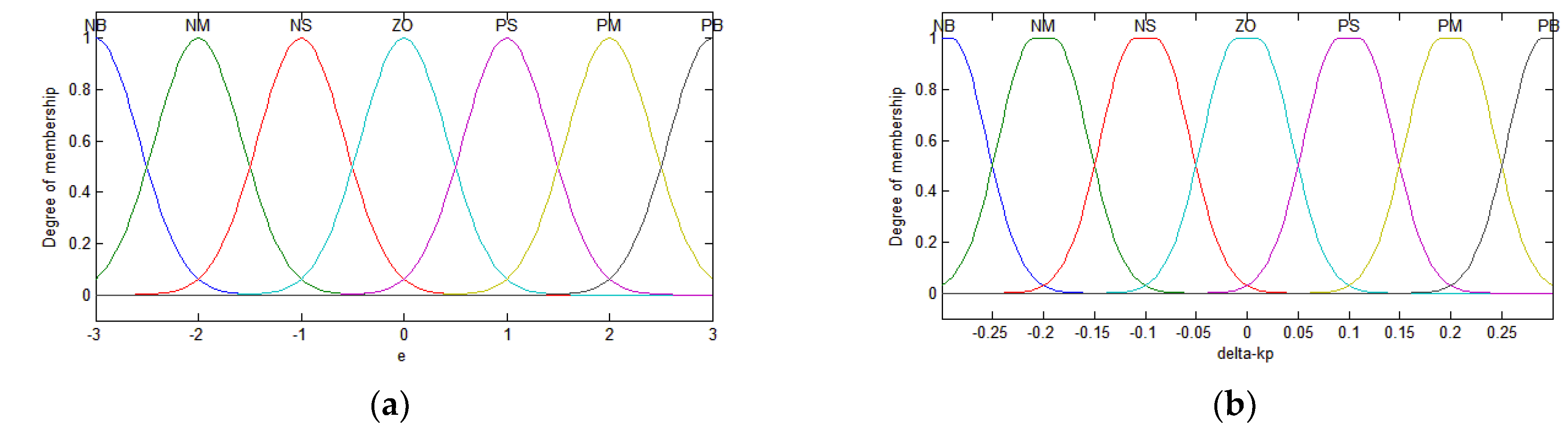
3.4.1. Determination of Membership Function

The determination of the membership function of input and output variables is a key link. In this paper, the input variables of the fuzzy controller are deviation E and deviation rate EC, and the output variables are Δkp, Δki, Δλ. The word sets describing input and output variables are {negative large, negative medium, negative small, zero, positive small, positive medium, positive large} and set their universe as {E, EC} = {−3, −2, −1, 0, 1, 2, 3} and the fuzzy subset as {NB, NM, NS, ZO, PS, PM, PB}. The fields of (−0.6, −0.4, −0.2, 0, 0.2, 0.4, 0.6}; (−0.06, −0.04, −0.02, 0.02, 0.04, 0.06}; (−0.3,−0.2, −0.1, 0.1, 0.2, 0.3} of (Δkp); and (0.06)*{−0.3, −0.2, −0.1, 0.1, 0.2, 0.3} of (Δki), (−0.04, −0.04, −0.06) of (Δλ). The membership function is the Gauss membership function with overlapping symmetric distribution. The membership curves of input and output variables are shown in Figure 4. Only one input and one output membership function are given. Figure 4a shows the membership function of input E and EC, and Figure 4b shows the membership function of output Δkp, Δki, Δλ.

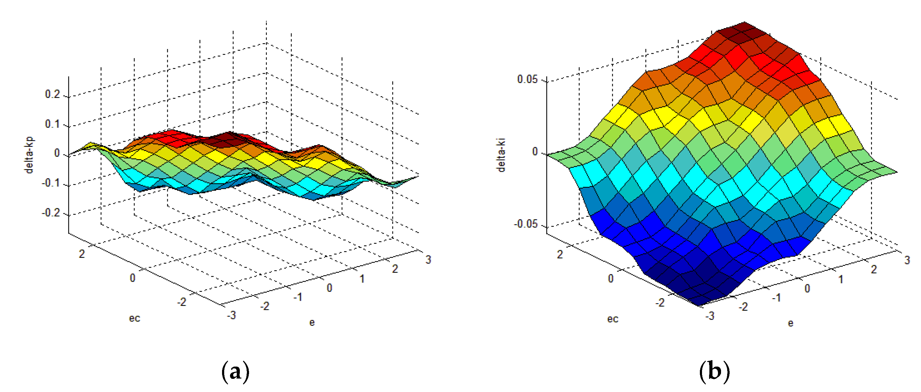
3.4.2. Parameter Tuning Rule of PIλ Controller

Adopting the characteristic analysis of fractional-order PID controller in reference [21,22], and combined with the experience of experts, the adjustment rules of parameters are finally determined. According to the real-time deviation E and the deviation change rate EC of the system, according to the experience, according to the setting principle and adjustment test, the rules are set in the fuzzy logic toolbox, and 49 control rules are obtained. The rule surface diagrams of the output and input variables are shown in Figure 5.
  • 1. (e==NB) & (ec==NB) => (delta_kp=PB)(delta_ki=NB)(delta_lamda=NB) (1)
  • 2. (e==NB) & (ec==NM) => (delta_kp=PB)(delta_ki=NB)(delta_lamda=NB) (1)
  • 3. (e==NB) & (ec==NS) => (delta_kp=PM)(delta_ki=NB)(delta_lamda=NB) (1)
  • 4. (e==NB) & (ec==ZO) => (delta_kp=PM)(delta_ki=NM)(delta_lamda=NM) (1)
  • 5. (e==NB) & (ec==PS) => (delta_kp=PS)(delta_ki=NM)(delta_lamda=NM) (1)
  • 6. (e==NB) & (ec==PM) => (delta_kp=PS)(delta_ki=ZO)(delta_lamda=ZO) (1)
  • 7. (e==NB) & (ec==PB) => (delta_kp=ZO)(delta_ki=ZO)(delta_lamda=ZO) (1)
  • ............
  • 43. (e==PB) & (ec==NB) => (delta_kp=ZO)(delta_ki=ZO)(delta_-lamda=ZO) (1)
  • 44. (e==PB) & (ec==NM) => (delta_kp=NS)(delta_ki=ZO)(delta_lamda=ZO) (1)
  • 45. (e==PB) & (ec==NS) => (delta_kp=NS)(delta_ki=PS)(delta_lamda=PS) (1)
  • 46. (e==PB) & (ec==ZO) => (delta_kp=NM)(delta_ki=PM)(delta_lamda=PM) (1)
  • 47. (e==PB) & (ec==PS) => (delta_kp=NM)(delta_ki=PB)(delta_lamda=PB) (1)
  • 48. (e==PB) & (ec==PM) => (delta_kp=NB)(delta_ki=PB)(delta_lamda=PB) (1)
  • 49. (e==PB) & (ec==PB) => (delta_kp=NB)(delta_ki=PB)(delta_lamda=PB) (1)

4. Simulation Research and Result Analysis

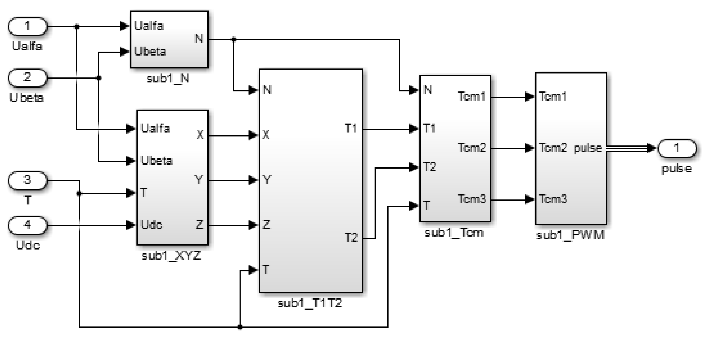
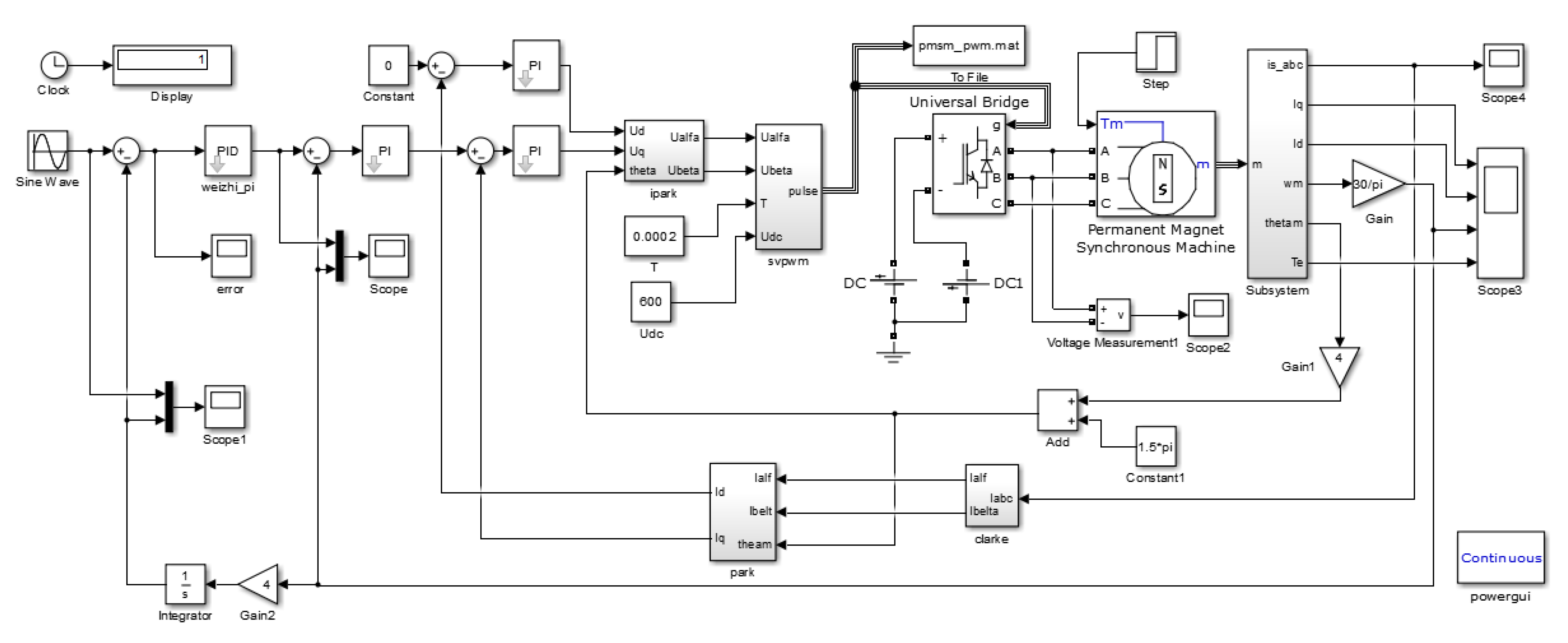
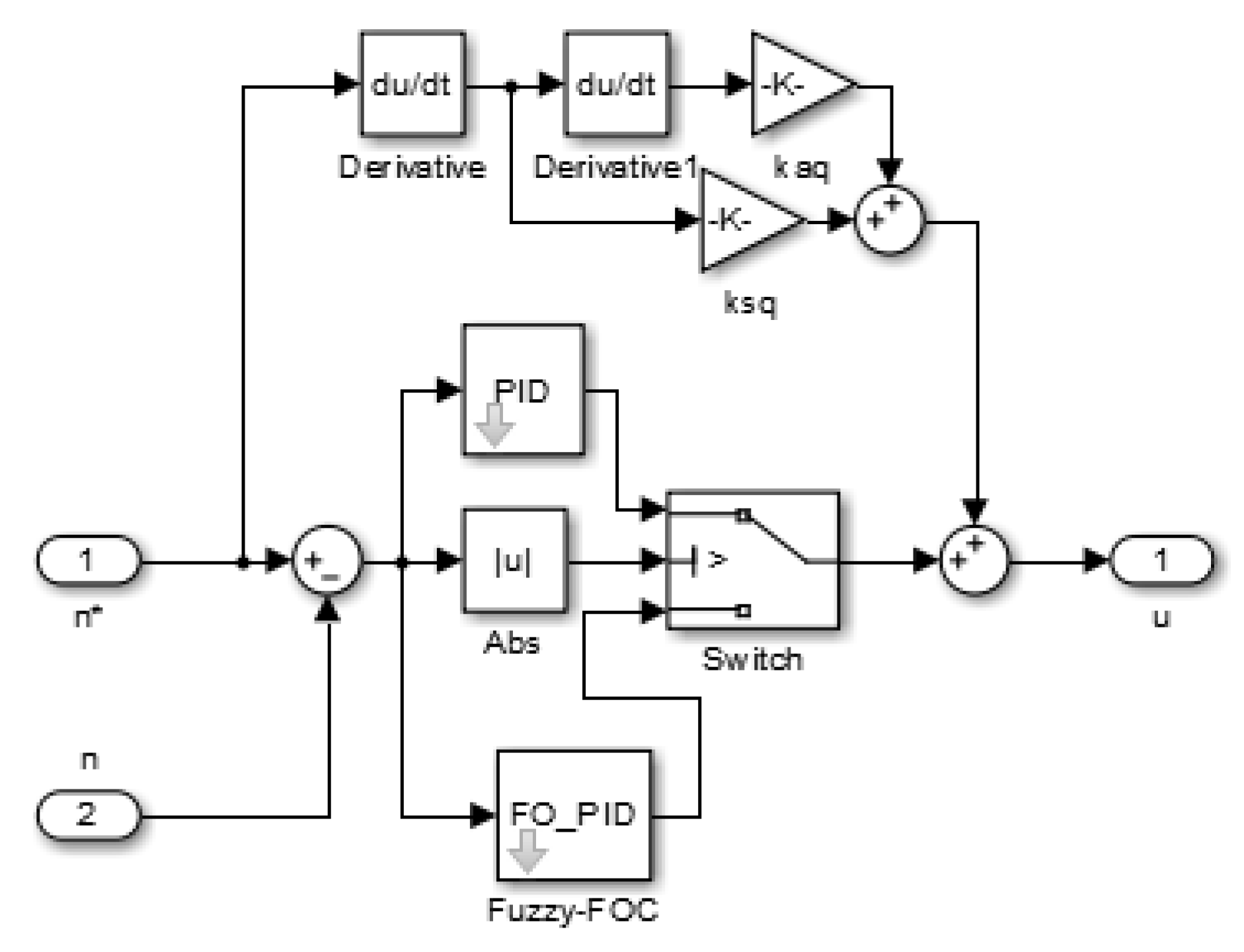
4.1. Three Closed-Loop PMSM Simulation Model

Using the Permanent Magnet Synchronous Motor (PMSM) module of Simulink/SimPowerSystem/Machines sublibrary, the simulation model of the system is established. The motor parameters are shown in Table 1.
The simulation model of three closed-loop permanent magnet synchronous motors in Simulink is established as shown in Figure 6. The simulation system consists of position regulator, speed regulator, current regulator, Park inverse conversion module, inverter module, SVPWM module, permanent magnet synchronous motor, parameter measurement module, Clark conversion module and Park conversion module. The system adopts three closed-loop control mode of position, speed and current. Both internal control loops adopt a digital PI controller, and the outer control loop is the position loop. Two different controllers, digital PI and fuzzy adaptive fractional PI lambda, are used as position regulators for simulation.

4.2. Simulation of Current Loop and Velocity Loop

Through the simulation of the current loop and speed loop, the simulation waveform of AC servo system is obtained as shown in Figure 7. The given speed is 1000 rad/s, no-load operation, and the simulation time is 0.05 s.
Figure 7a shows the speed waveform. It can be seen that the maximum speed of the system reaches 1100 rad, the overshoot is 10%, and the adjustment time is 0.026 s (±2% error band). The system can follow the given speed better, which indicates that the system has good follow performance. Figure 7b shows the torque waveform. It can be seen that in the early stage of motor starting, the torque fluctuates greatly, the maximum torque reaches 27 N·m, and the later stage is basically stable. Figure 7c,d are the wave-forms of iq and id respectively. The wave-forms of (0.085, 0.09) interval are intercepted, which are consistent with the results of theoretical analysis. It can be seen that the simulation model of the servo AC system is basically realized, and the established model can truly reflect the characteristics of the system.

4.3. Position PI Control

The position loop, current loop and speed loop are controlled by PI, and the parameters are optimized by particle swarm optimization algorithm, as shown in Table 2.

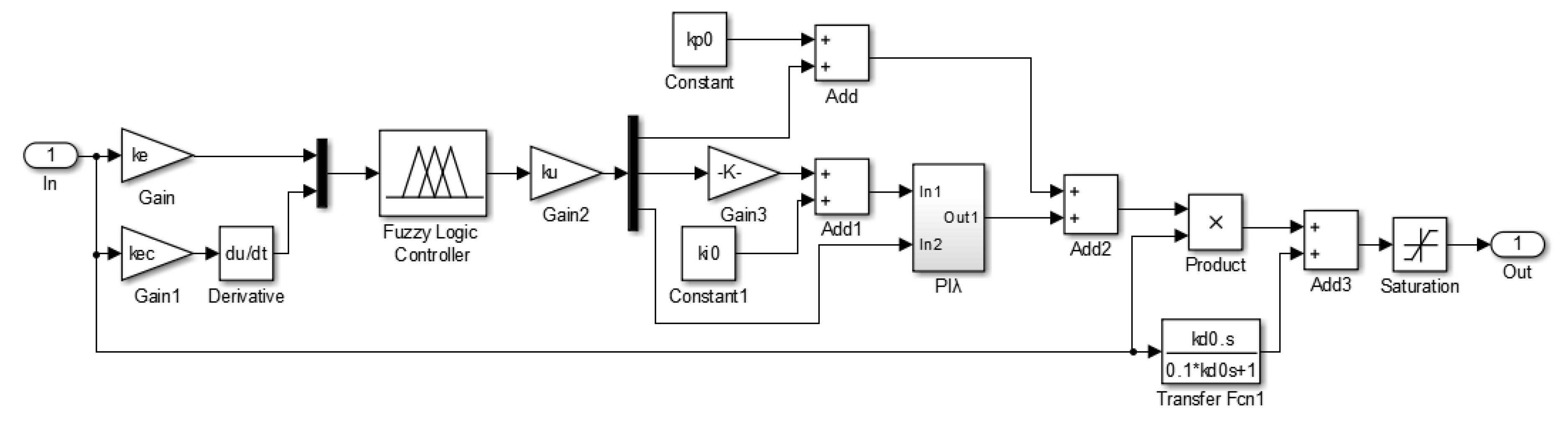
4.4. Fuzzy Fractional-Order PID Control (FO-PID)

The position loop is replaced by a fractional PI parameter self-tuning controller based on fuzzy logic [35,36,37]. The subsystem is shown in Figure 8. The fuzzy controller is designed with Fuzzy Logic Toolbox. The initial parameters of the fractional PI controller are kp0 = 100, ki0 = 5, and lambda = 0.8. The input-output proportional coefficients of the fuzzy controller are 1, 2 and 10, respectively.
The traditional PI control strategy and the fuzzy fractional PI control strategy are used to simulate the three closed-loop control system of PMSM. The sinusoidal input with 10 rad/s amplitude and 10 rad/s frequency is selected as the given trajectory. The simulation time is 1.5 s, and the simulation algorithm uses ode23tb. First, the system starts without load and runs with 0.5 s load (5   N · m ).
The results of the two control strategies are shown in Figure 9a is position tracking, Figure 9b is velocity tracking, Figure 9c is trajectory error, and Figure 9d is velocity error. It can be seen from Figure 9a that the trajectory of the motor achieves the tracking of the input signal, and the error curve is shown in Figure 9c. The traditional PI controller is used as the position loop regulator in the simulation experiment. The position tracking process has certain fluctuation, the rising time is longer and the regulating time is longer. After the sudden load disturbance, the position response fluctuation is larger, the recovery time is longer, the speed fluctuates greatly in a short time, and the speed deviation is larger in the start-up process.
It can be seen that the trajectory tracking error is small by using the fuzzy PIλ controller, and it has stronger robustness to load disturbance and better speed response in steady state.

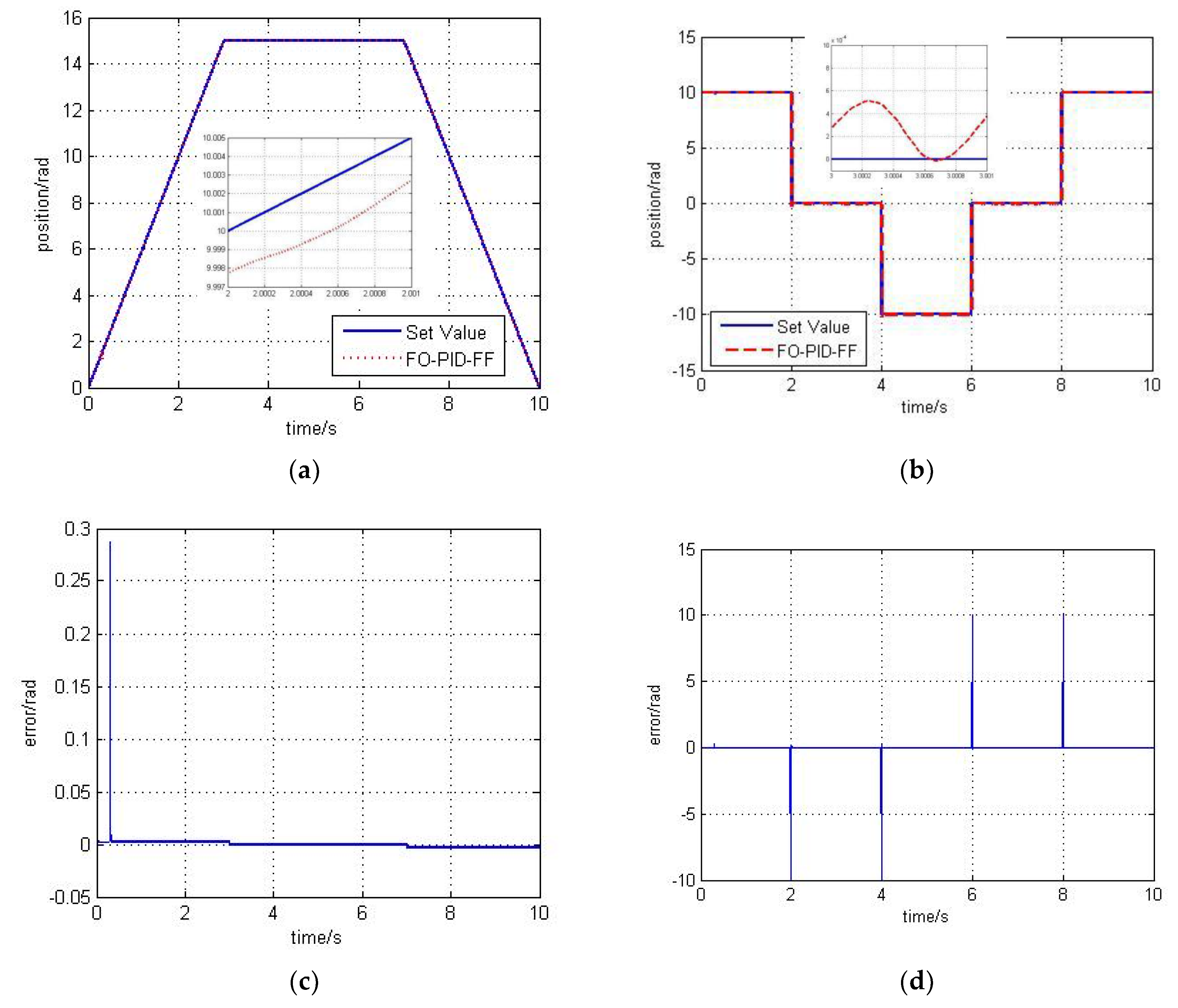
4.5. Compound Control with Speed Feed-Forward and Acceleration Feed-Forward (FO-PID-FF)

Generally, the random signal of system response is composed of step, constant velocity and sinusoidal signal. When the system is moving on a constant velocity slope, there will be a large tracking error. At this time, speed feed-forward signal should be added to implement the composite control of adaptive fuzzy PIλ and feed-forward compensation [26]:
u 1 = u + k s q × v c
In the formula: vc is a velocity value generated by differential position command signal, v c = ( x g ( n ) x g ( n 1 ) ) / T , T is the sampling period, n is the current moment, and ksq is the velocity feed-forward gain.
When the system moves sinusoidally, because the input signal is a second-order signal, only adding speed feed-forward compensation cannot achieve a good tracking effect. Therefore, acceleration feed-forward signal should be added to compensate the system, and the composite control of adaptive fuzzy PIλ, speed feed-forward and acceleration feed-forward is implemented.
u 1 = u + k s q * v c + k a q * v a
Among: kaq is the acceleration feed-forward gain, and va is the acceleration value differentiated by the velocity signal, v a = ( v c ( n ) v c ( n 1 ) ) / T .
The simulation model of the compound control of fuzzy PIλ and feed-forward compensation is established as shown in Figure 10.

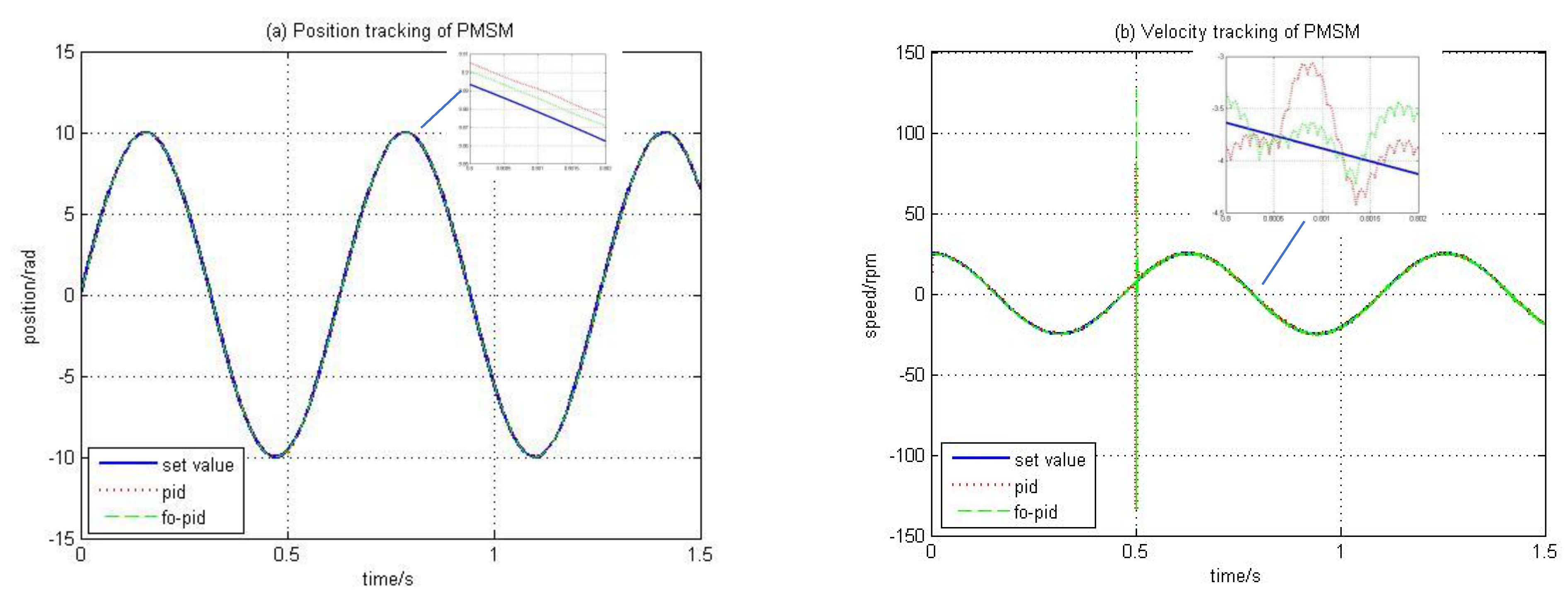
4.6. Performance Analysis of Three Position Control Strategies

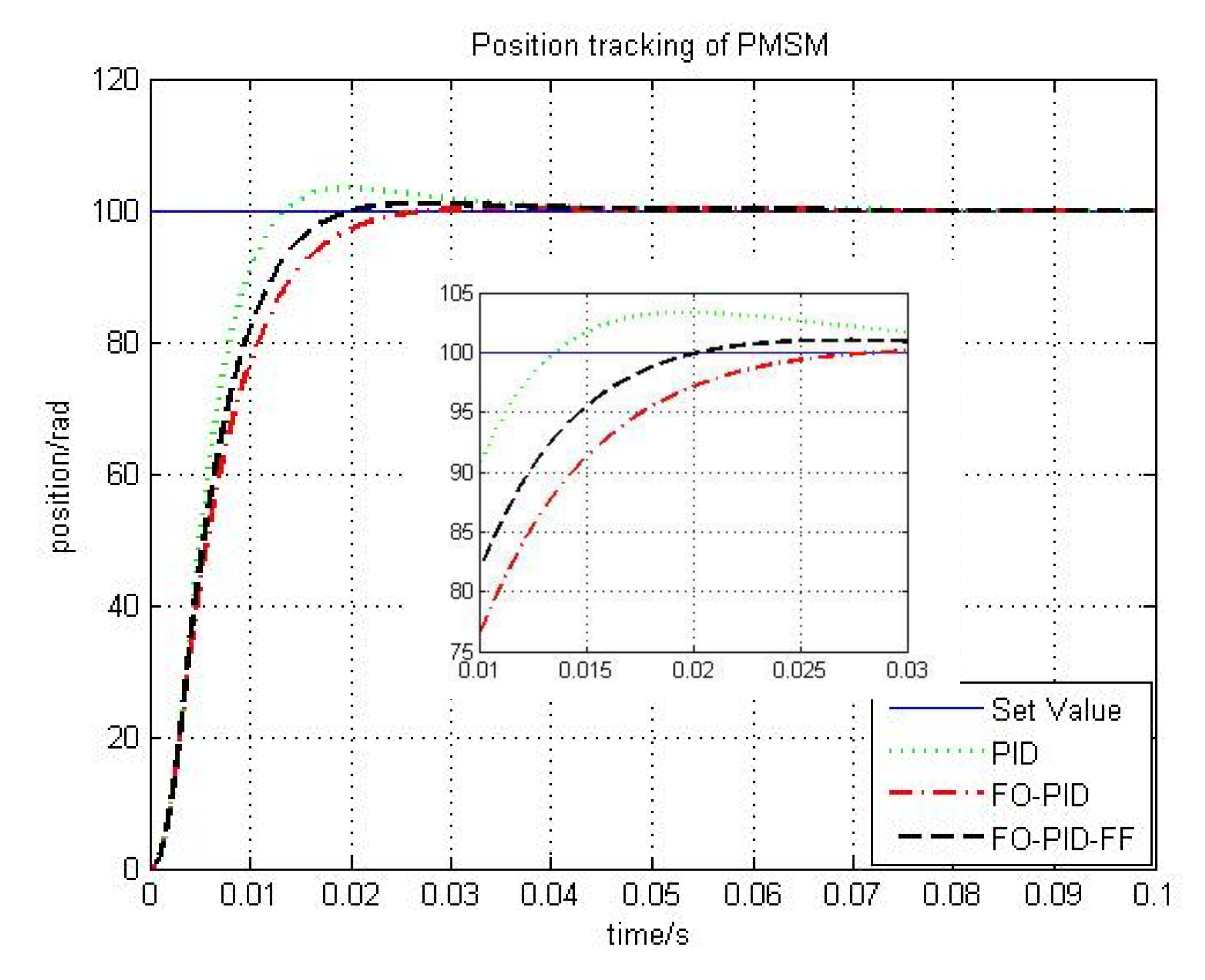
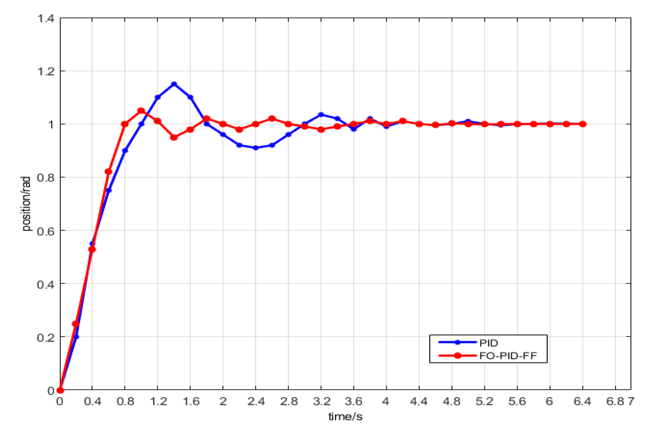
4.6.1. Motor Starting Stage

The step signal is used as the input signal. Given the position of 10, the simulation time is chosen to be 0–1 s. The step response curves of servo system position control under three kinds of controllers are shown in Figure 11. According to the data obtained from each curve, the performance comparison of the three control modes is calculated and listed as shown in Table 3.
The simulation results show that the three control strategies can reach the set value, PI control has 0.34% overshoot, and FO-PID controller and FO-PID-FF have smaller overshoot. From the time analysis, the rise time and adjustment time of FO-PID-FF are 0.0202 and 0.017, respectively, which are smaller than the response time of FO-PID. Considering the comprehensive performance, the effect of compound control is the best.

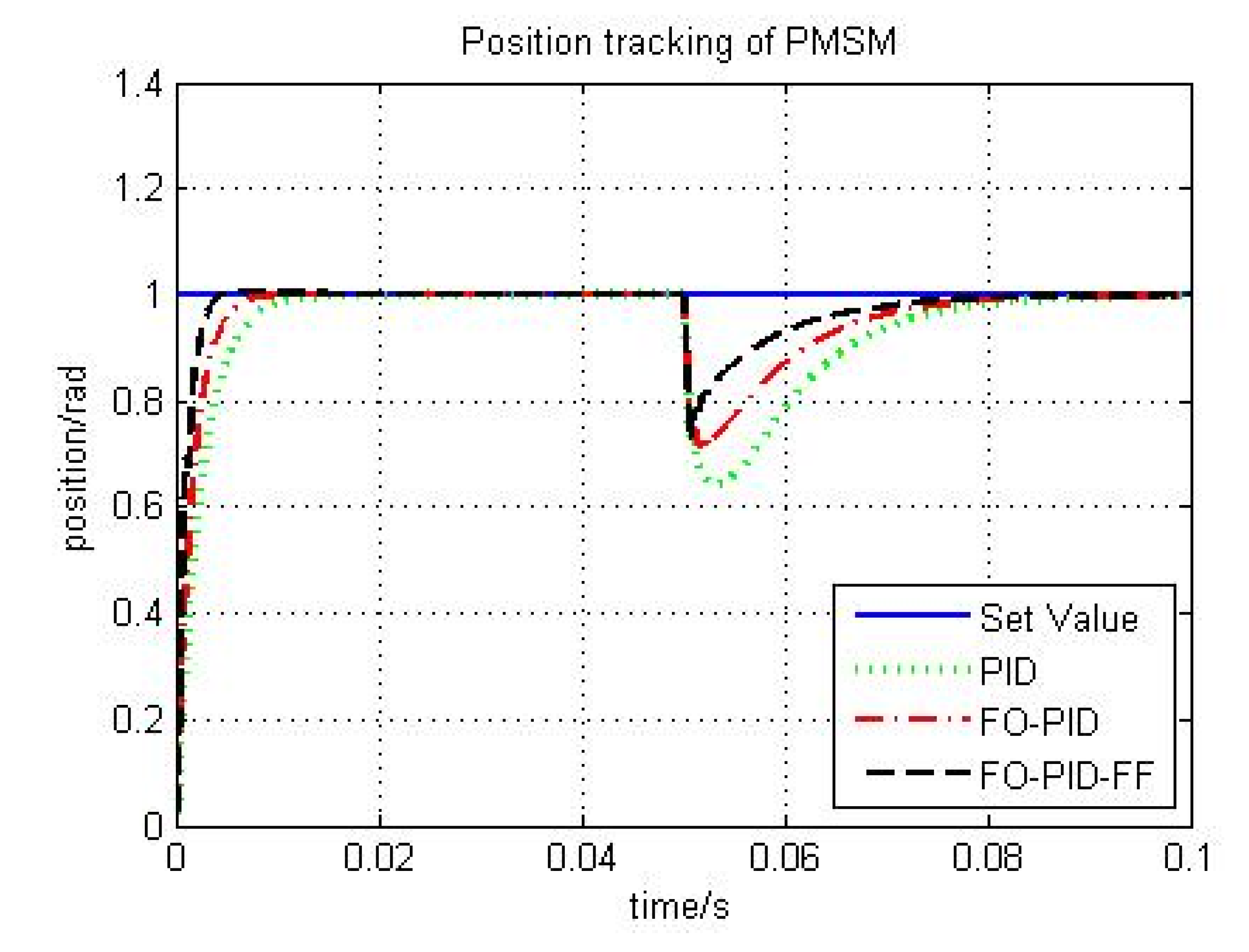
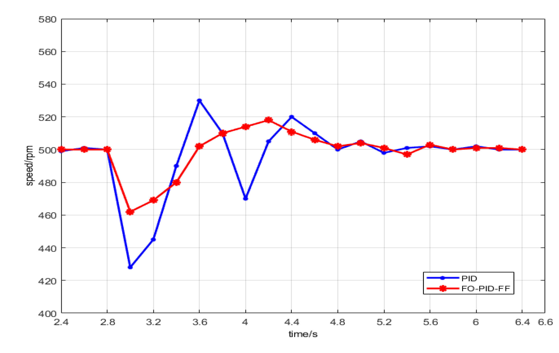
4.6.2. Load Disturbance Stage

The controller parameters’ modification by the fuzzy logic controller during load disturbance is also recorded. The proposed controller performance for the set-point change is illustrated in Figure 12. Based on this response, one can understand that the proposed FO-PID-FF controller outperforms the other two above-mentioned controllers.
As the changes in the input parameters are immediately observed and the necessary changes in the above-mentioned controller are done by the fuzzy logic controller, the FO-PID-FF exhibits better results than the other controllers. Hence, these results obviously indicate that the lively change of the value of the orders related to the controller parts of the FOC will enrich the robustness of the system. Based on the numerical comparison, the FO-PID-FF controller exhibits its strength with a significantly lower settling time and rise-time when compared to other controllers. With regard to error criterion, the FO-PID-FF controller features lower values for both ISE and IAE when compare to the FO-PID and PID controllers.

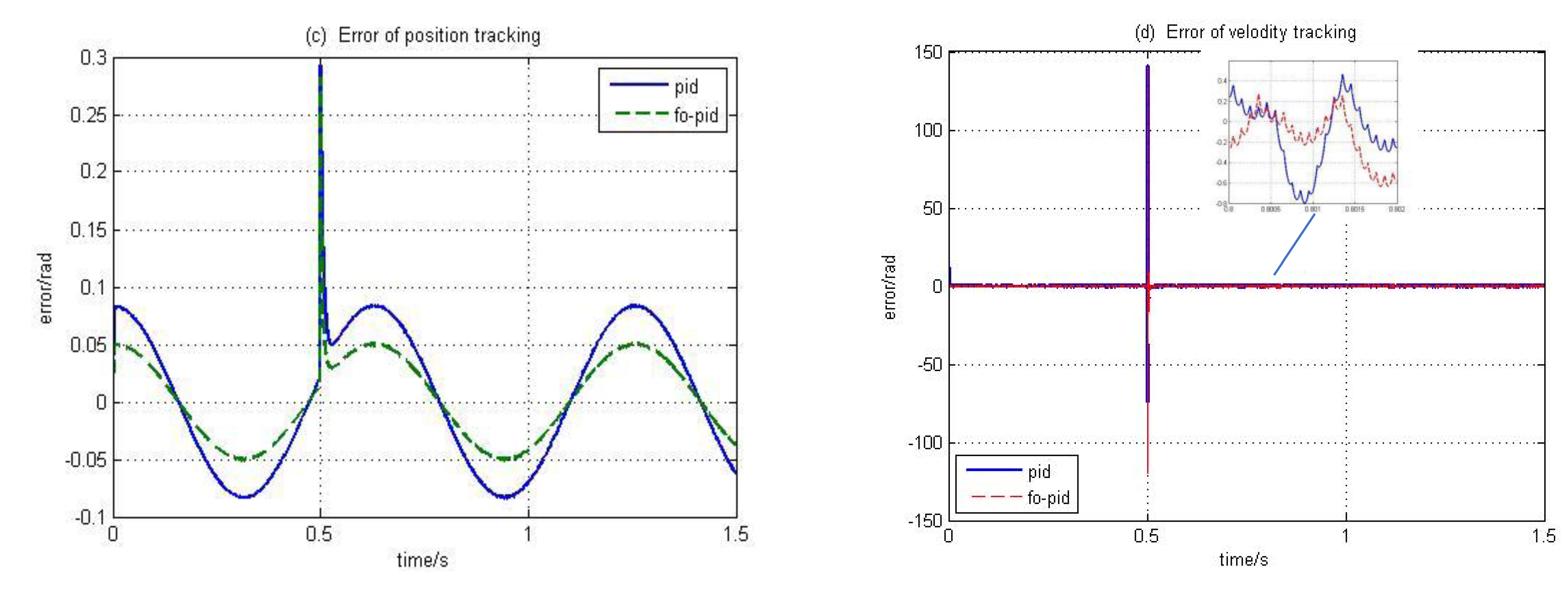
4.6.3. Other Trajectory Tracking Analysis

In order to verify the applicability and accuracy of the algorithm, the trapezoidal path and square wave path are selected respectively, and the output curve is shown in Figure 13. It has a good tracking effect for some different motion paths and can meet the performance requirements of robot motion control. Figure 13a is the trajectory tracking in the trapezoidal path, and Figure 13b is the trajectory tracking in the square wave path. From the result, the controlled object can move according to the given path using FO-PID-FF. Figure 13c is the trajectory error in the trapezoidal path, and Figure 13d is the trajectory error in the square wave path. Except for the initial stage and mutation time, the path tracking error is slightly larger, and the other time errors are with (−0.002, 0.002).

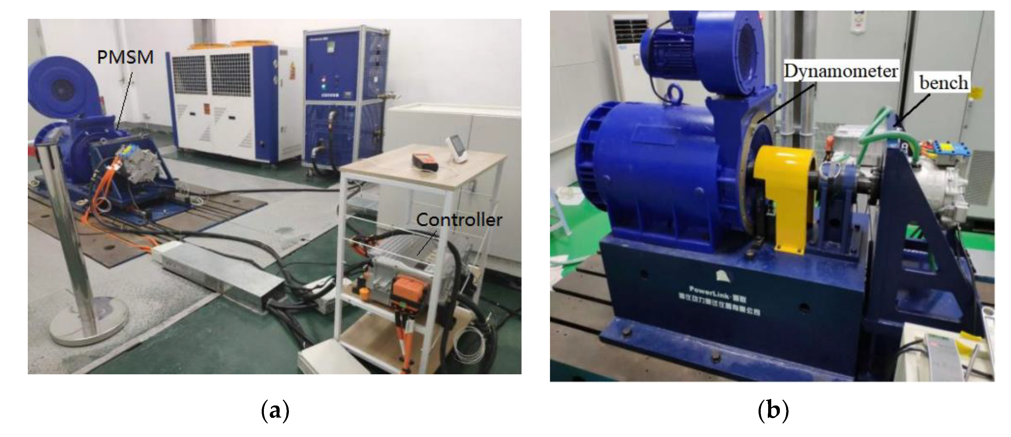
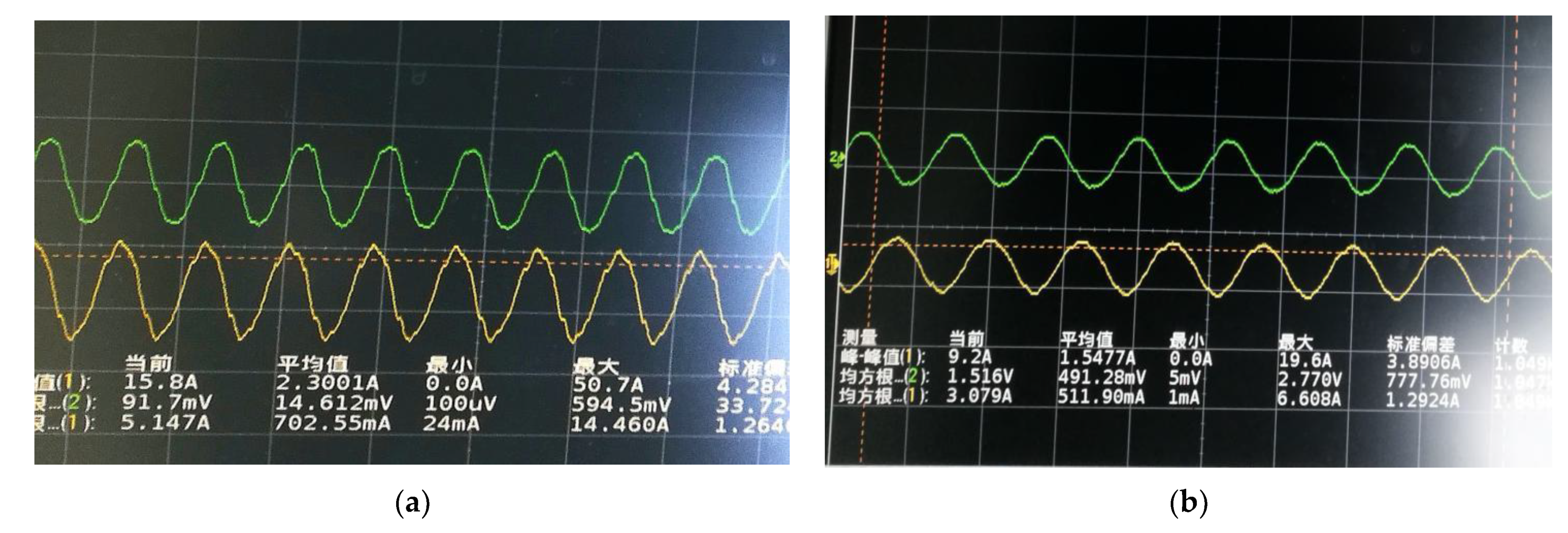
5. Experiment and Test

PMSM servo control system test equipment is as shown in Figure 14. The system mainly includes: PMSM, motion controller, upper computer, Dynamometer and bench. The permanent magnet synchronous motor is 80JASM102K-2500, 1000 W rated power, 5.15 A rated current, 3000 rpm rated speed, 3.18 N·m rated torque. The main controller uses STM32F405RG chip of ST company to design the control circuit and drive circuit.
According to the smoothness of the control signal waveform, the normal operation of the system equipment and signal can be checked. When the speed value is 100 rad/min and the speed value is 1000 rad/min, the waveform of output phase voltage is shown in Figure 15.
It can be seen from the figure that the output waveform of phase voltage presents good smoothness at low and high speeds. Therefore, the operation state and signal communication performance of each piece of equipment in the servo control system is good, which can be used to verify the active disturbance rejection control strategy and parameter setting results of PMSM.
(1)
Experiment of PMSM speed loop and current loop
The experimental conditions are set as follows: PMSM rotor operates at ω r * = 500   r / min without load, and the load T L = 0.15   N m is added suddenly at 3 s to verify the performance of PMSM AC servo system when it is no-load. The speed response curve of PMSM under PID and FO-PID-FF control mode is shown in Figure 16.
(2)
Experiment of PMSM position loop and velocity loop
The experimental conditions are set as follows: in order to verify the tracking performance of the motor rotor in PMSM AC servo control system, the given rotor position signal is the unit step signal. The PMSM position tracking curve under PID and FO-PID-FF control mode is shown in Figure 17.
When the given position signal is unit step input, it can be seen from Figure 17 that the rise time of position signal using PID control mode is about 1.1 s, the maximum peak value is 1.12 rad, there is 12% overshoot, and the adjustment time is 3.6 s. After entering the adjustment time, the curve shows a small range of high-frequency fluctuations. Using FO-PID-FF control mode, the rise time of position signal is about 0.9 s, the maximum peak value is 1.06 rad, there is 6% overshoot, and the adjustment time is 2.4 s. After entering the adjustment time, the curve fluctuation frequency is exceedingly small.
By comparing the measured curves of the speed response signal and position response signal, the strong robustness of fractional order fuzzy PID control strategy with feed-forward in PMSM servo control system is further verified, which can achieve small overshoot and fast steady state. The validity of the above simulation results and parameter self-tuning results are verified.

6. Conclusions

The application of fuzzy PIλ control in permanent magnet synchronous motor servo system is studied. The disadvantages of traditional PID control and the disadvantages of variable parameters, non-linearity, time delay and time variation of servo system are overcome by using the characteristics of fuzzy control such as non-linearity, variable structure, self-adaptation, self-tuning and strong robustness. Fuzzy parameter self-tuning fractional-order PI controller simulation results show that the control effect is better than the traditional PID control, and the desired system control effect can be obtained. After adding feed-forward compensation, the response speed is accelerated, the overshoot is small, and the parameters of the PID controller can be adjusted online and real-time according to the changes of the controlled object, which can reduce the system error; moreover, the system has strong robustness and is not susceptible to external interference and changes in system parameters. For AC servo system with non-linearity and time-varying parameters, the compound position control with fuzzy PIλ and feed-forward compensation can meet the requirements of system control and improve the dynamic and static characteristics of the system. With our regulator in relation to the PID regulator, we obtained a value so much better, and the approximate cost of application in relation to the classic PID regulator is reduced.

Author Contributions

C.-Q.Z. and L.W. conceived of and designed the method. C.-F.X. analyzed the data; C.-Q.Z. and L.W. established the model, validated the model by experiments and wrote the paper. All authors have read and agreed to the published version of the manuscript.

Funding

The work in this paper is supported by the National Key R&D Program of China (Grant No. 2018YFB1700100, 2018YFB1700204)), and Science and Technology Funds from Liaoning Provincial Natural Science Foundation Project (Grant No. 2019-ZD-0108).

Institutional Review Board Statement

Not applicable.

Informed Consent Statement

Not applicable.

Data Availability Statement

Not applicable.

Conflicts of Interest

The authors declare no conflict of interest.

References

  1. Xue, W.; Li, Y.L.; Cang, S.J.; Jia, H.; Wang, Z. Chaotic behavior and circuit implementation of a fractional-order permanent magnet synchronous motor model. J. Frankl. Inst. 2015, 352, 2887–2898. [Google Scholar] [CrossRef]
  2. Thakar, U.; Joshi, V.; Vyawahare, V. Design of fractional -order PI controllers and comparative analysis of these controllers with linearized, nonlinear integer-order and nonlinear fractional-order representations of PMSM. Int. J. Dyn. Control 2017, 5, 187–197. [Google Scholar] [CrossRef]
  3. Bao, X.P.; Ji, Z.; Zhu, T. Research and Development on high-performance PMSM servo system. Micromotors 2014, 47, 84–88. [Google Scholar]
  4. Liu, C.Q.; Luo, G.Z.; Tu, W.C.; Wan, H. Servo systems with double closed-loops based on active disturbance rejection controllers. Proc. CSEE 2017, 37, 7032–7039. [Google Scholar]
  5. Zuo, Y.F.; Zhang, J.; Liu, C.; Zhang, T. Integrated design for permanent magnet synchronous motor servo systems based on active disturbance rejection control. Trans. China Electrotech. Soc. 2016, 31, 51–58. [Google Scholar]
  6. Hou, R.M.; Liu, R.Z.; Hou, Y.L.; Gao, Q.; Yang, G.-L. Application of adaptive fuzzy wavelet neural sliding mode control in AC servo system. Acta Armamentarii 2014, 35, 769–775. [Google Scholar]
  7. Hou, R.M.; Liu, R.Z.; Gao, Q.; Wang, L.; Deng, T.-B. Application of adaptive fuzzy wavelet neural network in AC servo control system. Acta Armamentarii 2015, 36, 781–788. [Google Scholar]
  8. Zhang, B.B.; Zhao, D.Y.; Zhao, T. Adaptive sliding mode control based on disturbance observer for manipulator systems. Inf. Control. 2018, 47, 184–190. [Google Scholar]
  9. Zhang, B.T.; Pi, Y.G.; Luo, Y. Fractional order sliding-mode control based on parameters auto-tuning for velocity control of permanent magnet synchronous motor. Isa Trans. 2012, 5, 649–656. [Google Scholar] [CrossRef]
  10. Sun, G.H.; Ma, Z.Q. Practical tracking control of linear motor with adaptive fractional order terminal sliding mode control. IEEE/ASME Trans. Mechatron. 2017, 6, 2643–2653. [Google Scholar] [CrossRef]
  11. Yue, Y.B.; Zhang, R.K.; Wu, B.; Shao, W. Direct torque control method of PMSM based on fractional order PID controller. Data Driven Control Learn. Syst. 2017, 5, 411–415. [Google Scholar]
  12. Xie, Y.; Tang, X.; Song, B.; Zhou, X.; Guo, Y. Data-driven adaptive fractional order PI control for PMSM servo system with measurement noise and data dropouts. ISA Trans. 2018, 4, 172–188. [Google Scholar] [CrossRef]
  13. Zhang, B.T.; Pi, Y. Robust fractional order proportion-plus-differential controller based on fuzzy inference for permanent magnet synchronous motor. IET Control Theory Appl. 2012, 6, 829–837. [Google Scholar] [CrossRef]
  14. Ullah, N.; Al-Ahmadi, A.A. A triple mode robust sliding mode controller for a nonlinear system with measurement noise and uncertainty. Math. Found. Comput. 2020, 2, 81–89. [Google Scholar] [CrossRef]
  15. Mani, P.; Rajan, R.; Shanmugam, L. Adaptive fractional fuzzy integral sliding mode control for PMSM model. IEEE Trans. Fuzzy Syst. 2019, 27, 1674–1686. [Google Scholar] [CrossRef]
  16. Rajagopal, K.; Karthikeyan, A.; Duraisamy, P. Chaos suppression in fractional order permanent magnet synchronous generator in wind turbine systems. Nonlinear Eng. 2017, 6, 79–87. [Google Scholar] [CrossRef]
  17. Rajasekhar, A.; Abraham, A.; Pant, M. A hybrid differential artificial bee colony algorithm based tuning of fractional order controller for permanent magnet synchronous motor drive. Int. J. Mach. Learn. Cybern. 2014, 5, 327–337. [Google Scholar] [CrossRef]
  18. Delavari, H.; Ghaderi, R.; Ranjbar, A.; Momani, S. Fuzzy fractional order sliding mode controller for nonlinear systems. Commun. Nonlinear Sci. Numer. Simul. 2010, 4, 963–978. [Google Scholar] [CrossRef]
  19. Lin, T.C.; Kuo, C.H. H∞ synchronization of uncertain fractional order chaotic systems: Adaptive fuzzy approach. ISA Trans. 2011, 50, 548–556. [Google Scholar] [CrossRef]
  20. Aghababa, M.P. Comments on “H-infinity synchronization of uncertain fractional order chaotic systems: Adaptive fuzzy approach”. ISA Trans. 2012, 1, 11–12. [Google Scholar] [CrossRef]
  21. Zhang, Y.; Xia, X.W.; Li, F.Z.; Dong, M. An adaptive fuzzy sliding mode position controller for naval gun servo system. Acta Armamentarii 2015, 36, 67–72. [Google Scholar]
  22. Petras, I. Fractional Order Nonlinear Systems. Springer Publication: New York, NY, USA, 2011; pp. 65–78. [Google Scholar]
  23. Zhong, Q.S.; Bao, J.F.; Yu, Y.B.; Liao, X.-F. Impulsive control for fractional-order chaotic systems. Chin. Phys. Lett. 2008, 8, 2812–2815. [Google Scholar]
  24. Wang, L.; Zhong, C.Q. Design of optimal fractional-order PID controllers using particle swarm optimization algorithm for DC motor system. In Proceedings of the Advanced Information Technology, Electronic & Automation Control Conference, Chongqing, China, 19–20 December 2015; IEEE: Piscataway, NJ, USA,, 2015; pp. 175–179. [Google Scholar]
  25. Yuan, L.; Hu, B.X.; Wei, K.; Shen, S. The Control Principle and MATLAB Simulation of Modern Permanent Magnet Synchronous Motor; Beijing Aerospace University Press: Beijing, China, 2016; pp. 27–51. [Google Scholar]
  26. Yuan, D.K.; Xu, Y.D.; Li, X.T. Variable Frequency Speed Regulating System of Permanent Magnet Synchronous Motor and Its Control; Machinery Industry Press: Beijing, China, 2016; pp. 55–60. [Google Scholar]
  27. Ramezanian, H.; Balochian, S.; Zare, A. Design of optimal fractional-order PID controllers using particle swarm optimization algorithm for Automatic voltage regulator (AVR) system. J. Control Autom. Electr. Syst. 2013, 24, 601–611. [Google Scholar] [CrossRef]
  28. Kanagaraj, N. Design and performance evaluation of fuzzy variable fractional-order [PI]λDµ controller for a class of first-order delay-time systems. Stud. Inform. Control 2019, 28, 443–452. [Google Scholar] [CrossRef]
  29. Rydel, M.; Stanisławski, R.; Latawiec, K.J. Balanced truncation model order reduction in limited frequency and time intervals for discrete-time commensurate fractional-order systems. Symmetry 2019, 11, 258. [Google Scholar] [CrossRef] [Green Version]
  30. Rydel, M.; Stanisławski, R. A new frequency weighted Fourier-based method for model order reduction. Automatica 2018, 88, 107–112. [Google Scholar] [CrossRef]
  31. Srivastava, H.M.; Sayed, A.M.; Gaafar, F.M. A class of nonlinear boundary value problems for an arbitrary Fractional-Order differential equation with the riemann-stieltjes functional integral and infinite-point boundary conditions. Symmetry 2018, 10, 508. [Google Scholar] [CrossRef] [Green Version]
  32. Chalishajar, D.; Kumar, A. Existence, uniqueness and Ulam’s stability of solutions for a coupled system of fractional differential equations with integral boundary conditions. Mathematics 2018, 6, 96. [Google Scholar] [CrossRef] [Green Version]
  33. Cattani, C.; Srivastava, H.M.; Yang, X.-J. Fractional Dynamics; Emerging Science Publishers: Berlin, Germany; Warsaw, Poland, 2015. [Google Scholar]
  34. Hamani, S.; Benchora, M.; Graef, J.R. Existence results for boundary-value problems with nonlinear fractional differential inclusions and integral conditions. Electron. J. Q. Theory Differ. Equ. 2013, 20, 1–16. [Google Scholar]
  35. Chen, Y.; Zhao, T.; Dian, S.Y.; Zeng, X.; Wang, H. Balance adjustment of power-line inspection robot using general type-2 fractional order fuzzy PID controller. Symmetry 2020, 12, 479. [Google Scholar] [CrossRef] [Green Version]
  36. Mendel, J.M. General type-2 fuzzy logic systems made simple: A tutorial. IEEE Trans. Fuzzy Syst. 2014, 22, 1162–1182. [Google Scholar] [CrossRef]
  37. Kumbasar, T.; Hagras, H. A self-tuning zSlices-based general type-2 fuzzy PI controller. IEEE Trans. Fuzzy Syst. 2015, 23, 991–1013. [Google Scholar] [CrossRef] [Green Version]
Figure 1. Principle diagram of three closed-loop permanent magnet synchronous motor vector control; θ * is the trajectory of a given position, θ is the actual location, N * is the control signal from the output of the position controller, N is the actual speed, i d * and i q * are the given current components on d-axis and q-axis respectively, ud and uq are the voltages of d-axis and q-axis respectively, u α and u β are the voltages of α -axis and β -axis obtained by inverse Park transform respectively, Ia and Ib are the currents of a and b phases respectively, I α and I β are the currents of α -axis and β -axis obtained by Clark transform respectively, Id and Iq are the currents of d-axis and q-axis respectively, FOPI is a fuzzy fractional-order PI controller, PIλ is a fractional order PI controller.
Symmetry 13 01118 g001
Figure 2. Structure of space vector pulse width modulation algorithm.
Symmetry 13 01118 g002
Figure 3. Fuzzy parameter self-tuning FOPI controller; (a) Principle diagram of fuzzy parameter self-tuning FOPI controller; (b) Structure diagram of fuzzy controller.
Symmetry 13 01118 g003
Figure 4. Membership curve of input and output variables; (a) Membership curves of E and EC; (b) Membership curves of Δkp, Δki, Δλ.
Symmetry 13 01118 g004
Figure 5. Rule surface map of output variables; (a) Rule surface map of between Δkp(or Δki) and two inputs (E and EC); (b) Rule surface map of between Δλ and two inputs (E and EC).
Symmetry 13 01118 g005
Figure 6. Simulation block diagram of AC servo system.
Symmetry 13 01118 g006
Figure 7. Simulation results of AC servo system; (a) Speed waveform; (b) Torque waveform; (c) iq waveform; (d) id waveform.
Symmetry 13 01118 g007
Figure 8. Simulation model of fuzzy PIλ controller.
Symmetry 13 01118 g008
Figure 9. Simulation results of fuzzy PIλ position controller; (a) Position tracking of PMSM; (b) Speed tracking PMSM; (c) Error of position tracking; (d) Error of speed tracking.
Symmetry 13 01118 g009aSymmetry 13 01118 g009b
Figure 10. Compound control model of fuzzy PIλ and feed-forward compensation.
Symmetry 13 01118 g010
Figure 11. Step response curves of three control strategies.
Symmetry 13 01118 g011
Figure 12. System response for the load disturbance.
Symmetry 13 01118 g012
Figure 13. Trajectory tracking results under two different paths; (a) The trajectory tracking in trapezoidal path; (b) The trajectory tracking in square wave path; (c) The trajectory error in trapezoidal path; (d) The trajectory error in square wave path.
Symmetry 13 01118 g013
Figure 14. PMSM servo control system test equipment; (a) PMSM and motion controller; (b) Dynamometer and bench.
Symmetry 13 01118 g014
Figure 15. Phase voltage output waveform; (a) Phase voltage output waveform when speed is 100 rad/min; (b) Phase voltage output waveform when speed is 1000 rad/min.
Symmetry 13 01118 g015
Figure 16. PMSM speed response curve.
Symmetry 13 01118 g016
Figure 17. PMSM position tracking curve.
Symmetry 13 01118 g017
Table 1. Parameters of permanent magnet synchronous motor.
Parameter Name (Unit) Value
Stator resistance R ( Ω )0.975
Stator inductance Ld, Lq (H)0.0085
Flux of Permanent Magnet Rotor in Stator Loop λ (Wb)0.175
Rotating inertia of rotor and load J ( k g m 2 )0.00008
Viscous friction coefficient F ( N m s )4.047 × 10⁻⁴
Pole logarithm of motor p4
Table 2. Parameters of the system regulator.
RegulatorProportional PIntegral I
Location loop1005
Speed loop0.116
id current loop301900
iq current loop301900
Table 3. Performance comparison table of three position controllers.
Position RegulatorRise-Time/sOvershoot/%Settling Time/s
PI controller0.01350.340.028
FO-PID0.02910.020.022
FO-PID-FF0.02020.100.017
Publisher’s Note: MDPI stays neutral with regard to jurisdictional claims in published maps and institutional affiliations.

