Article

Endotracheal Tubes Design: The Role of Tube Bending

1
Medical School, University of Nicosia, Nicosia CY-2417, Cyprus
2
Institut Mines-Telecom, 91120 Palaiseau, France
*
Author to whom correspondence should be addressed.
Symmetry 2021, 13(8), 1503; https://doi.org/10.3390/sym13081503
Submission received: 17 May 2021 / Revised: 13 June 2021 / Accepted: 4 August 2021 / Published: 16 August 2021
(This article belongs to the Special Issue Biofluids in Medicine: Models, Computational Methods and Applications)

Abstract

:
Endotracheal tubes (ETT) passed inside the human trachea witness tube bending at different angles, affecting the local fluid flow dynamics. This induces a variable mechanical ventilation performance across patients’ comfortability levels. Our understanding of the local fluid flow dynamics phenomena is thus crucial to enhance the maneuverability of ETT under operation. For the first time to our knowledge, we shed light on ETT through computational fluid dynamics (CFD) to investigate the bending effect of ETT on the local airflow in volume-controlled mechanical ventilation. We considered an ETT with 180° arc bend configuration, including Murphy’s eye. We identified several flow phenomena associated with the bending, such as flow asymmetries, secondary flows, and vortex dynamics throughout the tube.

1. Introduction

Endotracheal tubes (ETT) are frequently used in the medical sector to provide mechanical ventilation to patients [1]. They are usually employed for long periods during anesthesia and surgical operations to give oxygen to the human lungs. They were also extensively used in intensive care units of hospitals during the last two years for COVID-19 patients. ETT is manufactured and delivered under different diameters and lengths. Their maneuverability is very complex and constitutes a susceptible procedure for their installation inside the human trachea. This is due to the bending of the tube that must fit well to the mouth-to-trachea internal topology.
ETT aims to cover a wide range of humans trachea tomographies. Farrow et al., 2012 [2] addressed the role of ETT size and its selection depending on the patient’s physiology and conditions. Calderon et al., 2019 [3] investigated the mean flow and airway resistance in ETT of several diameters (6 to 10 mm) at average body temperature and constant pressure numerically. They showed that a single-sized ETT could facilitate endotracheal intubation (ET) without causing an increased airway resistance.
Recent research studies on ETT emerged during the last two years because of the COVID-19 pandemic [4,5,6,7,8]. Piazza et al., 2021 [9] shed light on long-term intubation and the high rate of tracheostomy in COVID-19 patients. Interestingly, they explained how this might determine an unprecedented increase in airway stenoses.
Thanks to advances in computer hardware and CFD methods and models, researchers can investigate the flow phenomena inside the human airways with considerable accuracy. For example, Kou et al., 2018 [10] studied the effect of the cough peak flow rate on airflow dynamics during a cough process in a CT (computerized tomography) scanned human respiratory airway model. Krenkel et al., 2010 [11] developed CFD simulations and experiments to investigate the impact of an ETT on the flow in a generic trachea (artificial lung ventilation). They shed light on models with bendings and connectors that induce more substantial secondary flows that can persist for long periods. Qi et al., 2014 [12] applied CFD simulations to study the airflow mechanisms in the trachea and main bronchi for individuals with left pulmonary artery sling. Other scientists used numerical tools to investigate airflow in the human trachea at different conditions [13,14]. Mechanical ventilation (MV) has also been a recent topic of research by some investigators [15,16,17,18,19,20] in attempts to quantify the impact of different MV modes on the aerodynamics of the airways in specific patients.
Kingma et al., 2017 [21] conducted a recent comparison of four methods of endotracheal tube passage in simulated airways. They showed a need for improved techniques to enhance ETT design for better local airflow in the human airways (e.g., human trachea bifurcations) induced by artificial MV.
This study concerns CFD simulations to investigate the airflow dynamics in human trachea first bifurcation from an ETT with Murphy’s eye [22,23,24]. We focus on the ETT vital role in inducing high local airflow circulations inside the trachea with symmetry and asymmetry features of the flow. This work shed light on the importance of appropriate manipulation of ETT during MV that physical practitioners and medical doctors usually manipulate.

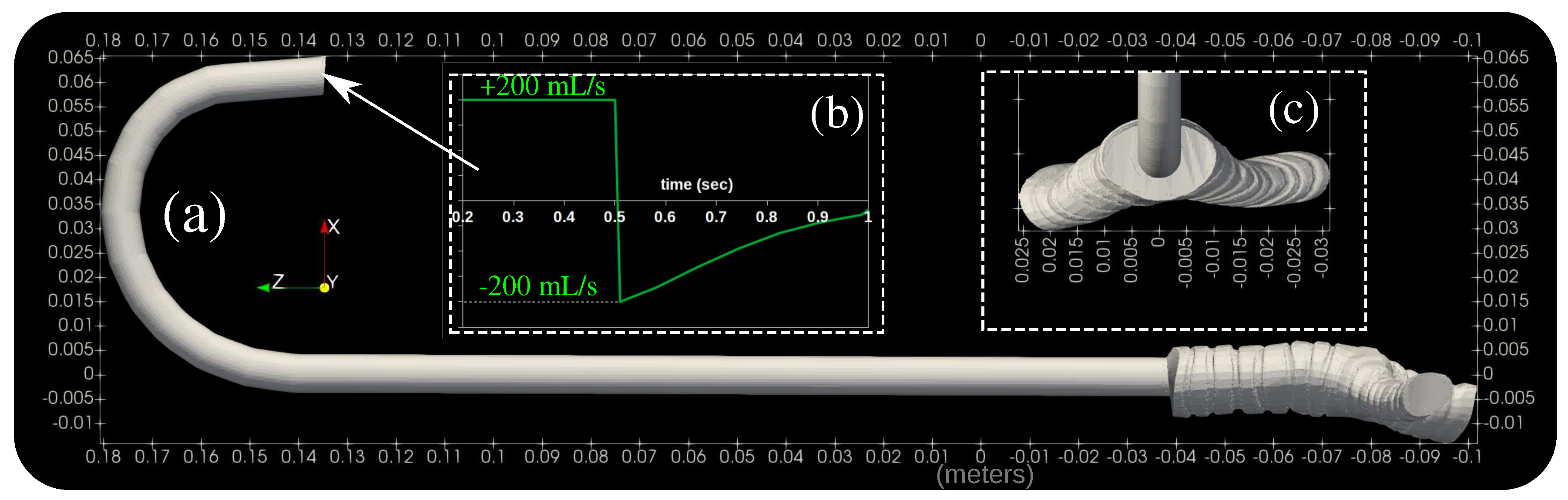
2. Computational Methodology

We employed the three-dimensional (3D) transient compressible Navier–Stokes equations:
ρ t + · ( ρ U ) = 0
( ρ U ) t + · ( ρ U U ) = P + · τ
( ρ E ) t + · [ ( ρ E + P ) U ] = · ( τ · U ) ,
where ρ , ⊗, U , P, E, τ represent the fluid density; tensorial product operator; velocity vector; pressure; internal energy and the shear stress tensor, respectively. The system of Equations (1)–(3) is discretized over the computational domain using the Finite Volume Method (FVM) [25,26] inside the open-source CFD code OpenFOAM® [27]. We model turbulence through the Reynolds-Averaged-Navier–Stokes in conjunction with the k ω S S T model [28,29]. We conducted a mesh sensitivity analysis using three different grids. According to the Grid Convergence Index (GCI) by Celik et al. [30], we adopted a 3D non-uniform hexahedral mesh of about 1 million cells, including local mesh refinement. The trachea geometry is from a commercial provider of a scanned adult patient trachea, transformed into STL surface and treated to retrieve the zone of interest shown in Figure 1c. We applied an inhale–exhale breath with a transient flow rate profile (Figure 1b) imposed at the entry of the ETT extremity. This flow rate mimics a real volume-control (VC) mechanical ventilation signal. A VC ventilation cyclic mode is the most effective one and known to provide full mechanical ventilation. Applying mechanical ventilation with VC mode allows a better control such that for each inspiratory effort beyond a threshold, the ventilator will inject the initially predefined fixed tidal volume. The airflow temperature is imposed 22 °C at the entry and 33 °C at the ETT walls. An outlet pressure condition with atmospheric pressure value as a reference and an outlet zero Neumann temperature boundary condition were applied at the two outlets of the trachea (Figure 1). The trachea walls are assumed to be rigid walls with no-slip velocity conditions.

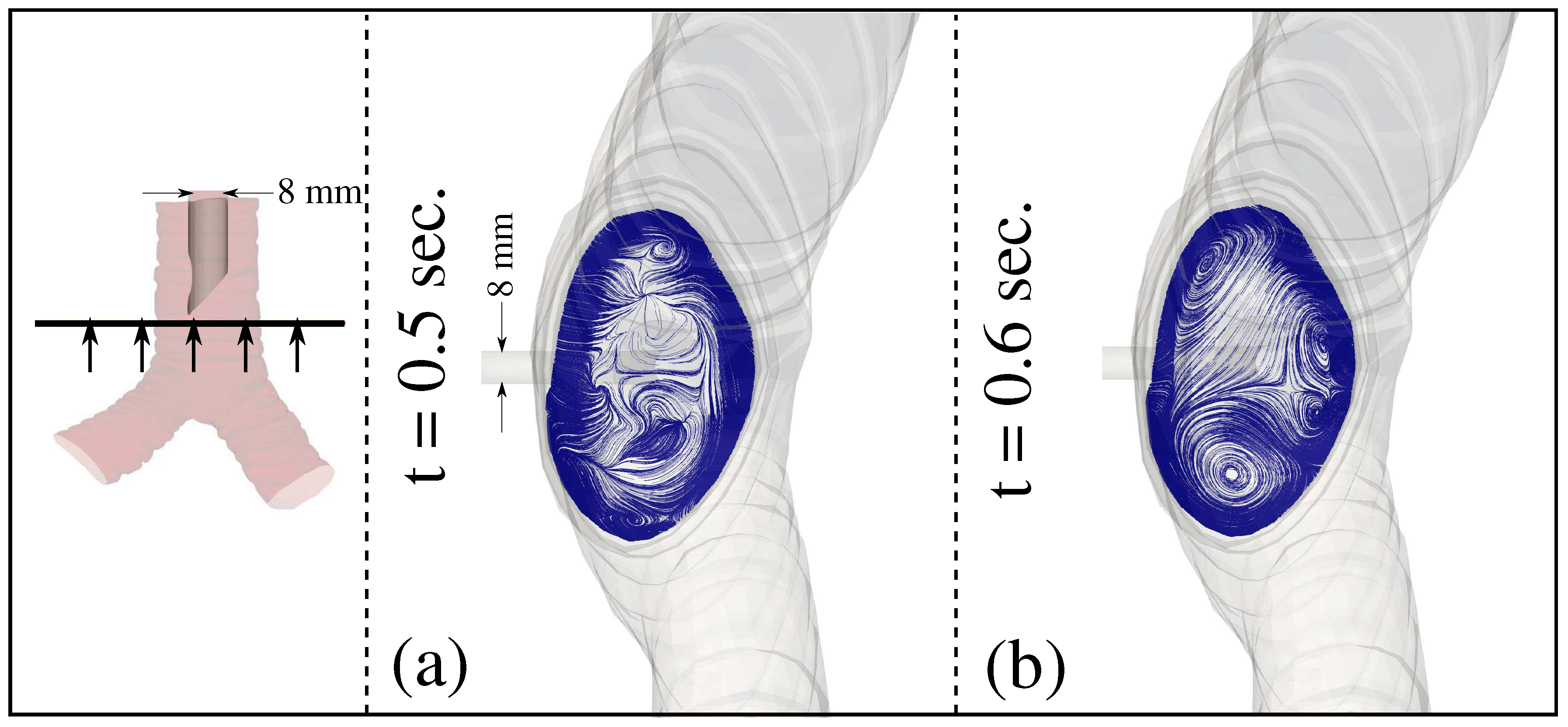
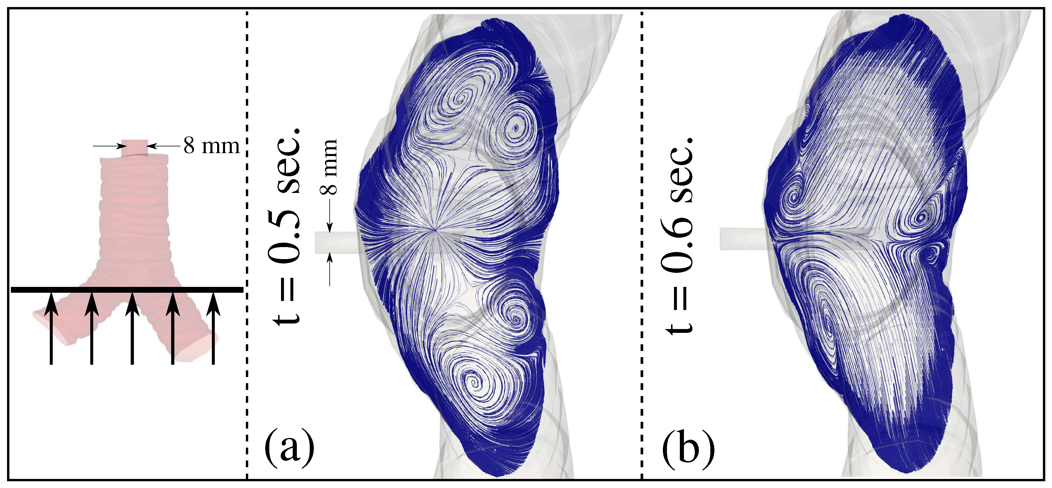
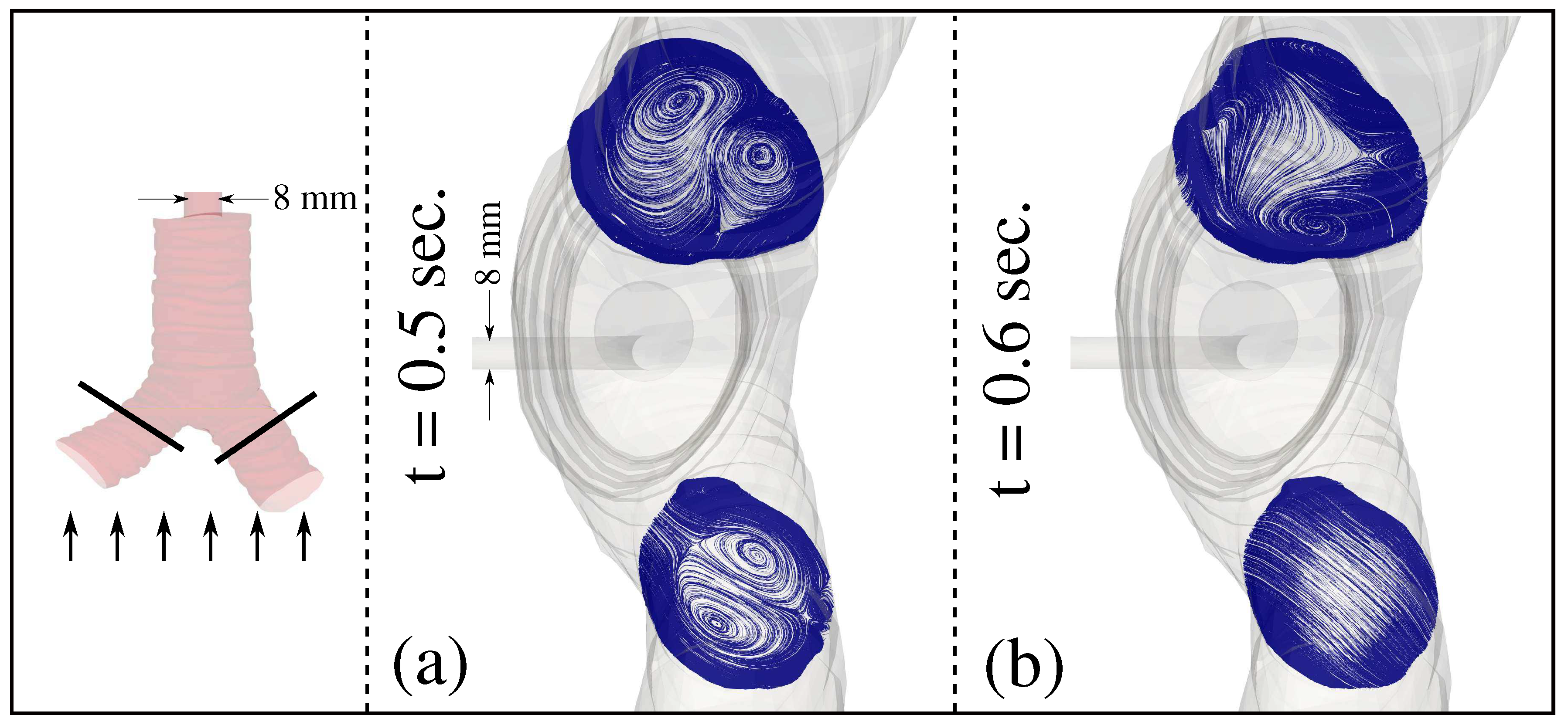
3. Results and Discussion

Figure 2 shows the local velocity streamlines in a cross-section post to the ETT extremity and before the bifurcation zone. At the end of the inhale period at t = 0.6 s (see Figure 2a), airflow asymmetry and small circulations near the trachea wall are observed. We have chosen those two times according to the flow rate cycle shown in Figure 1b. They represent the times at which the highest stresses can occur. The t = 0.5 s represents the maximum flow speed imposed during the inhalation period just before the exhalation period. The t = 0.6 s corresponds to the approximate maximum flow speed at the beginning of the exhalation period. At the beginning of the exhale period at t = 0.6 s (see Figure 2b), airflow asymmetry becomes less manifested with one big circulation (vortex) and the other three smaller vortices near the trachea wall. Note that strong vortices may induce damage to the trachea wall (e.g., inflammation, cracks), especially in patients with MV applied for long periods [9]. Figure 3 illustrates the local streamlines in a cross-section post to the ETT extremity and very close to the first bifurcation zone inside the trachea. At the end of the inhale period at t = 0.5 s (see Figure 3a), airflow symmetry and four medium to large vortices near the trachea wall are observed. At the beginning of the exhale period at t = 0.6 s (see Figure 3b), airflow symmetry is still prevailing, but with four small vortices at different positions compared to those observed at t = 0.5 s in Figure 3a.
Following the bifurcation zone, at the end of inhale period at t = 0.5 s, Figure 4a shows vital airflow circulations with two large vortices in each branch of the trachea. The local 3D streaklines and WSS are illustrated in Figure 5. Two large vortices at t = 0.5 s induce significant wall shear stress (WSS), as shown in Figure 5c. These two vortices per branch that were observed at the inhale period at t = 0.5 s become manifested, but only in the most significant branch addition alone at the beginning of the exhale period at t = 0.6 s (see Figure 4b).
The WSS values are in the same order of magnitude as those reported in the iterature for an ETT (see Rhein et al., 2016 [15]). They are higher than the WSS values reported in the iterature by Qi et al., 2014 [12] for a subject with a left pulmonary artery sling of the trachea (a numerical study without an ETT [12]). During the inhale phase, the ETT tube of Figure 1 induces more WSS values in the trachea zone following the first bifurcation (Figure 5c,d). In contrast, during the exhale period, it induces more airflow circulations in the trachea zone before the first bifurcation (Figure 5a,b). The flow direction reversibility can explain the differences in the streaklines of Figure 5a,b, and thus its adaptation to different topologies with the flow direction. In Figure 5a, the flow goes from top to bottom (inhale), thus entering a bifurcation of two outlets, while in Figure 5b, the flow moves from bottom to top (exhale), thus entering Murphy’s eye of the ETT.

4. Conclusions and Perspectives

We shed light on the vital role of ETT bendings in affecting the local airflow in the human trachea during an MV under a VC mode. Employing CFD modeling and simulation, we showed complex local airflow phenomena inside the human trachea that can be observed easily within experiments. In this paper, we focused on an ETT with Murphy’s eye and with an arc bending of 180°. Our computations revealed that the ETT tube with this bending angle during the inhale phase induces more WSS values in the trachea zone post to the first bifurcation. Furthermore, our numerical results showed that EET induces more airflow circulations in the trachea zone before the first bifurcation during the exhale period.
The present paper aimed only at raising the question of the bending tube issue through results that demonstrate the complex flow features such as the secondary vortices. At present, the medical practitioner’s community are not aware that these effects exist and can potentially cause harm to the patient. We aim at studying different configurations and provide a comparative study of different tubes and bendings in a future article.

Author Contributions

Conceptualization, T.D. and D.D.; methodology, T.D.; software, T.D.; formal analysis, T.D. and D.D.; investigation, T.D. and D.D.; resources, T.D. and D.D.; writing—original draft preparation, T.D.; writing—review and editing, D.D.; visualization, T.D.; supervision, D.D. Both authors have read and agreed to the published version of the manuscript.

Funding

This research received no external funding.

Data Availability Statement

All the data supporting reported results are available upon request from the authors.

Acknowledgments

The authors thank the Editorial board for their efforts in publishing this paper.

Conflicts of Interest

The authors declare no conflict of interest.

Abbreviations

The following abbreviations are used in this manuscript:
CFDComputational Fluid Dynamics
CTComputerized Tomography
ETEndotracheal Intubation
ETTEndotracheal Tube
FVMFinite Volume Method
GCIGrid Convergence Index
MVMechanical Ventilation
VCVolume Controlled
WSSWall Shear Stress

References

  1. Benumof, J.L. Airway Management: Principles and Practice; Mosby: St. Louis, MO, USA, 1996. [Google Scholar]
  2. Farrow, S.; Farrow, C.; Soni, N. Size matters: Choosing the right tracheal tube. Anaesthesia 2012, 67, 815–819. [Google Scholar] [CrossRef]
  3. Calderon, L.G.; Moreira, M.M.; Barreto, G.; Tincani, A.J. Model of single-sized endotracheal tube for adults. Einstein 2019, 18, eAO4805. [Google Scholar] [CrossRef] [Green Version]
  4. Gandhi, A.; Sokhi, J.; Lockie, C.; Ward, P.A. Emergency Tracheal Intubation in Patients with COVID-19: Experience from a UK Centre. Anesthesiol. Res. Pract. 2020, 2020, 8816729. [Google Scholar] [CrossRef]
  5. Duggan, L.V.; Mastoras, G.; Bryson, G.L. Tracheal intubation in patients with COVID-19. CMAJ 2020, 192, E607. [Google Scholar] [CrossRef] [PubMed]
  6. Onayemi, A.; Pai, B.H.P. Endo tracheal tube exchange in a COVID positive patient. J. Clin. Anesth. 2020, 66, 109941. [Google Scholar] [CrossRef]
  7. Orser, B.A. Recommendations for Endotracheal Intubation of COVID-19 Patients. Anesth. Analg. 2020, 130, 1109–1110. [Google Scholar] [CrossRef] [PubMed]
  8. World Health Organization. Technical Specifications of Medical Devices for the Case Management of COVID-19 in Healthcare Settings; Technical Report; World Health Organization: Washington, DC, USA, 2020. [Google Scholar]
  9. Piazza, C.; Filauro, M.; Dikkers, F.; Nouraei, S.; Sandu, K.; Sittel, C.; Amin, M.; Campos, G.; Eckel, H.; Peretti, G. Long-term intubation and high rate of tracheostomy in COVID-19 patients might determine an unprecedented increase of airway stenoses: A call to action from the European Laryngological Society. Eur. Arch. Otorhinolaryngol. 2021, 278, 1–7. [Google Scholar] [CrossRef] [PubMed]
  10. Kou, G.; Li, X.; Wang, Y.; Lin, M.; Zeng, Y.; Yang, X.; Yang, Y.; Gan, Z. CFD Simulation of Airflow Dynamics During Cough Based on CT-Scanned Respiratory Airway Geometries. Symmetry 2018, 10, 595. [Google Scholar] [CrossRef] [Green Version]
  11. Krenkel, L.; Wagner, C.; Wolf, U.; Scholz, A.; Terekhov, M.; Rivoire, J.; Schreiber, W. Protective Artificial Lung Ventilation: Impact of an Endotracheal Tube on the Flow in a Generic Trachea. In New Results in Numerical and Experimental Fluid Mechanics VII; Springer: Berlin/Heidelberg, Germany, 2010; pp. 505–512. [Google Scholar] [CrossRef]
  12. Qi, S.; Li, Z.; Yue, Y.; Van Triest, H.; Kang, Y. Computational fluid dynamics simulation of airflow in the trachea and main bronchi for the subjects with left pulmonary artery sling. BioMed. Eng. OnLine 2014, 13, 85. [Google Scholar] [CrossRef] [Green Version]
  13. Wright, P.; Marini, J.; Bernard, G. In vitro versus comparison of endotracheal tube airflow resistance. Am. Rev. Respir. Dis. 1989, 140, 10–16. [Google Scholar] [CrossRef]
  14. Malvè, M.; Chandra, S.; López-Villalobos, J.L.; Finol, E.A.; Ginel, A.; Doblaré, M. CFD analysis of the human airways under impedance-based boundary conditions: Application to healthy, diseased and stented trachea. Comput. Methods Biomech. Biomed. Eng. 2013, 16, 198–216. [Google Scholar] [CrossRef] [PubMed]
  15. Van Rhein, T.; Alzahrany, M.; Banerjee, A.; Salzman, G. Fluid flow and particle transport in mechanically ventilated airways. Part I. Fluid flow structures. Med. Biol. Eng. Comput. 2016, 54, 1085–1096. [Google Scholar] [CrossRef] [PubMed]
  16. Lumb, A.B.; Burns, A.D.; Figueroa Rosette, J.A.; Gradzik, K.B.; Ingham, D.B.; Pourkashanian, M. Computational fluid dynamic modelling of the effect of ventilation mode and tracheal tube position on air flow in the large airways. Anaesthesia 2015, 70, 577–584. [Google Scholar] [CrossRef] [Green Version]
  17. Lzahrany, M.; Van Rhein, T.; Banerjee, A.; Salzman, G. Fluid flow and particle transport in mechanically ventilated airways. Part II: Particle transport. Med. Biol. Eng. Comput. 2016, 54, 1097–1109. [Google Scholar] [CrossRef]
  18. Zhu, L.; Shen, J.; Gong, X.; Liu, L.; Liu, J.; Xu, Z. Effects of Different Modes of Mechanical Ventilation on Aerodynamics of the Patient-Specific Airway: A Numerical Study. In Proceedings of the 2019 41st Annual International Conference of the IEEE Engineering in Medicine and Biology Society (EMBC), Berlin, Germany, 23–27 July 2019; pp. 4961–4964. [Google Scholar] [CrossRef]
  19. Katz, I.; Milet, A.; Chalopin, M.; Farjot, G. Numerical analysis of mechanical ventilation using high concentration medical gas mixtures in newborns. Med. Gas Res. 2019, 9, 213–220. [Google Scholar] [CrossRef] [PubMed]
  20. Yousefi, M.; Safikhani, H.; Jabbari, E.; Yousefi, M.; Tahmsbi, V. Numerical modeling and Optimization of Respirational Emergency Drug Delivery Device using Computational Fluid Dynamics and Response Surface Method. Int. J. Eng. 2021, 34, 547–555. [Google Scholar] [CrossRef]
  21. Kingma, K.; Hofmeyr, R.; Zeng, I.; Coomarasamy, C.; Brainard, A. Comparison of four methods of endotracheal tube passage in simulated airways: There is room for improved techniques. Emerg. Med. Australas. 2017, 29, 650–657. [Google Scholar] [CrossRef] [PubMed] [Green Version]
  22. Forestner, J.E. Frank J. Murphy, M.D., C.M., 1900–1972: His life, career, and the Murphy eye. Anesthesiology 2010, 113, 1019–1025. [Google Scholar] [CrossRef] [Green Version]
  23. Tamakawa, S. Every endotracheal tube needs a Murphy eye! Can. J. Anaesth. 1999, 46, 998–999. [Google Scholar] [CrossRef] [Green Version]
  24. Krzanowski, T.J.; Mazur, W. A complication associated with the Murphy eye of an endotracheal tube. Anesth. Analg. 2005, 100, 1854–1855. [Google Scholar] [CrossRef]
  25. Ferziger, J.H.; Peric, M. Computational Methods for Fluid Dynamics; Springer: Berlin/Heidelberg, Germany, 1999. [Google Scholar]
  26. Moukalled, F.; Mangani, L.; Darwish, M. The Finite Volume Method in Computational Fluid Dynamics: An Advanced Introduction with OpenFOAM and Matlab, 1st ed.; Springer International Publishing: Cham, Switzerland, 2016. [Google Scholar]
  27. Jasak, H. OpenFOAM: Open source CFD in research and industry. Int. J. Nav. Archit. Ocean Eng. 2009, 1, 89–94. [Google Scholar] [CrossRef] [Green Version]
  28. Menter, F. Two-Equation Eddy-Viscosity Turbulence Models for Engineering Applications. AIAA J. 1994, 32, 1598–1605. [Google Scholar] [CrossRef] [Green Version]
  29. Wilcox, D.C. Turbulence Modeling for CFD; DCW Industries, Inc.: La Canada, CA, USA, 2007. [Google Scholar]
  30. Celik, I.B.; Ghia, U.; Roache, P.J.; Freitas, C.J. Procedure for Estimation and Reporting of Uncertainty due to Discretization in CFD Applications. J. Fluids Eng. 2008, 130, 078001. [Google Scholar] [CrossRef] [Green Version]
Figure 1. Endotracheal tube (ETT) 3D model of 8 mm internal diameter inserted into a human’s trachea. (a) The computational model used in the simulations; (b) the inhale/exhale applied flow rate boundary condition that mimics a real volume-controlled (VC) mechanical ventilation (MV); (c) upper view of the ETT showing the trachea first bifurcation.
Symmetry 13 01503 g001
Figure 2. Local velocity streamlines in a cross-section post to the ETT extremity and before the bifurcation zone. (a) Velocity streamlines at the end of the inhale period at t = 0.5 s; (b) velocity streamlines at the beginning of the exhale period at t = 0.6 s.
Symmetry 13 01503 g002
Figure 3. Local velocity streamlines in a cross-section post to the ETT extremity and very close to the bifurcation zone. (a) Velocity streamlines at the end of the inhale period at t = 0.5 s; (b) velocity streamlines at the beginning of the exhale period at t = 0.6 s.
Symmetry 13 01503 g003
Figure 4. Local velocity streamlines in a cross-section post to the ETT extremity and post to the bifurcation zone. (a) Velocity streamlines at the end of the inhale period at t = 0.5 s; (b) velocity streamlines at the beginning of the exhale period at t = 0.6 s.
Symmetry 13 01503 g004
Figure 5. Three dimensional velocity streaklines (a,b) colored by the axial velocity values U z (m/s), and the local wall shear stress (c,d) values W S S (Pa) observed from a top view perspective. (a,c) At the end of the inhale period at t = 0.5 s; (b,d) at the beginning of the exhale period at t = 0.6 s. The small arrows in (c) indicate high local WSS values.
Symmetry 13 01503 g005
Publisher’s Note: MDPI stays neutral with regard to jurisdictional claims in published maps and institutional affiliations.

