Abstract
Robotic machining has obtained growing attention recently because of the low cost, high flexibility and large workspace of industrial robots (IRs). Multiple degrees of freedom of IRs improve the dexterity of machining while causing the problem of redundancy. Meanwhile, the performance of IRs, such as their stiffness and dexterity, is affected by their position and posture obviously. Therefore, a redundant posture optimization method for robotic milling is proposed to improve the machining performance of the robot. The multiple characteristics of the robot are considered, including the joint-limit, singularity and stiffness, which have symmetry in its workspace. Firstly, the joint-limit is regarded as the constraint. And a symmetrical and effective constraint method is proposed to simply guarantee that all the interpolation points can avoid joint interference. Then, the performance indices of singularity and stiffness are designed as the optimization target. On this basis, the piecewise-global-optimization-strategy (PGOS) is proposed for redundant optimization. Owning to the PGOS, all the given planned tool points in their corresponding segment are considered simultaneously to avoid the gradual deterioration in traditional methods, which is especially suitable for the machining process with a continuous path. Moreover, the computational load of the optimization solution is considered and limited by the designed segmentation strategy. Finally, a series of comparative simulations are conducted to validate the good performance of the proposed method.
1. Introduction
Presently, CNC machine tools are the mean equipment for metal cutting, which is suitable for production with high precision and large quantity [1]. However, conventional CNC machine tools suffer from several limitations in the production of large size and small batches, such as high cost and low flexibility [2,3]. In recent years, robotic machining by industrial robots (IRs), especially robotic milling, has attracted growing attention owing to the low cost, high flexibility and large workspace of IRs [4].
As shown in Figure 1, a six revolute (6R) serial robot is usually employed to construct a robotic milling system where the spindle is mounted as the end-effector (EE). The computer-aided manufacturing (CAM) system designed for five-axis CNC milling, such as the Mastercam and Siemens NX, is usually used to generate the target milling path with a series of tool points [5,6]. During the milling process, the motion control of the 6R robot needs six coordinates at each milling point, including three position coordinates to locate the tool center point (TCP) and three posture coordinates to orient the EE [7]. However, the typical CAM system can only provide five coordinates without the rotational degree of freedom (DoF) around the tool axis [8], which can be represented by a coordinate in the Euler frame as shown in Figure 1. Hence, the absent needs to be determined for the robot controller for the following posture tracking [9,10], which can be summed up as a planning problem of redundant DoF.
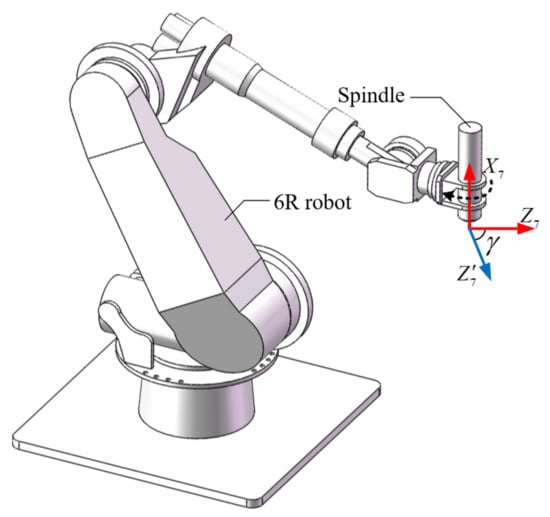
Figure 1.
Layout of the robotic milling system and the redundant coordinate.
The coordinate can be directly selected as a fixed value, which solves the redundancy problem reluctantly. However, the dexterity of the 6R robot is lost. In addition, the performance, such as the singularity and stiffness of EE, changes with the position and posture of IRs, which affects the machining quality directly [11]. Therefore, optimization planning considering the performance of the robot is the most reasonable and valuable mode for the redundancy problem [12]. For 6R robotic milling, three main performances are widely considered, including joint-limit, singularity and stiffness of EE, which are introduced in detail as follows:
- Joint-limit performance
Joint-limit performance is always regarded as one of the optimization targets to avoid joint interference. Zhu et al. [13] define a joint-limit index to keep each joint angle away from the limit boundary and its value range is . A similar joint-limit index is designed and applied in [14], which obtains a similar optimization result.
In general, the purpose of these performance indices and their optimization is to maintain each joint angle close to the middle of the limit range. In fact, this is not necessary because the joint-limit is to avoid joint interference of mechanical structure but has no effect on the motion performance when approaching the boundary. Therefore, the joint-limit does not need to be the optimization target but should be the constraint for judgment.
In this regard, some researchers use the joint-limit as the constraint to judge whether each joint angle of the planned tool points is within the limit range [15,16]. However, these methods can only ensure the joint-limit avoidance of the planned tool points. But the middle interpolation points between the planned points are ignored, which might result in the risk of joint interference due to the complex nonlinear mapping between Cartesian space and the joint space of IRs.
- Singularity performance
The singularity of IRs affects their motion performance obviously and the singular configuration should be kept away during the milling process. Hence, singularity performance should be regarded as one of the optimization targets.
Several singularity performance indices, such as the manipulability index [17] and the condition number of the Jacobian matrix [18], are designed as the distance metrics to avoid the singularity. The condition number of Jacobian has many different forms and reflects the transfer relationship between force and motion [13]. Among them, the condition number defined in the Frobenius norm [19] is the most widely used owing to the low computational load. These singularity performance indices have different value ranges and can be selected according to the application requirements.
- Stiffness performance
The stiffness performance affects the machining accuracy and surface quality directly and is the most important factor limiting the application of robot machining compared with CNC machine tools [20]. The greater stiffness of robot EE can obtain better machine quality [21]. Therefore, stiffness performance should be regarded as one of the optimization targets.
The stiffness matrix of robot EE in Cartesian space can reflect the operational stiffness. However, is the tensor index with various parameters and is difficult to use in optimization solutions directly. Hence, the scalar index needs to be constructed. Assuming the robot link is rigid and the joint is elastic, the stiffness distribution of robot EE is an ellipsoid, which is called a stiffness or compliance ellipsoid. Several scalar stiffness indices are designed based on stiffness ellipsoids for different occasions. To improve the accuracy and efficiency of robotic drilling, Jiao et al. [14] and Chen et al. [22] select maximizing the stiffness in the normal direction of the workpiece as the optimization target. Correspondingly, the stiffness indices are designed to describe the deviation of the long axis of the stiffness ellipsoid from the normal direction. Xiong et al. [23] proposes a feed direction stiffness index where the stiffness along the feed direction is maximized to obtain a high feed rate. Guo et al. [7] selects the volume of the stiffness ellipsoid as a performance index to improve the overall machining quality. Similarly, several overall indices are defined in [22,24,25]. These indices realize the scalar metrics of stiffness performance in different aspects and can be selected for specific applications.
Based on the above constraint and performance indices, various redundant posture optimization methods are developed. The stiffness and singularity performance are considered respectively in [8,22]. For better comprehensive performance, the joint-limit and singularity indices are combined as the optimization target in [13,23]. However, as mentioned before, taking a joint-limit as an optimization objective is unnecessary and might limit the performance of IRs. Jiao et al. [14] and Xiong et al. [24] consider three factors simultaneously, where the joint-limit and singularity are used as judgmental constraints. Nevertheless, the threshold of the singularity index is difficult to determine due to the lack of clear physical meaning. Lin et al. [16] takes the stiffness and singularity indices as the optimization targets, respectively. Meanwhile, the constraint for the variation range of between two adjacent planned tool points, which is called the displacement constraint of , is considered to ensure the machining efficiency and quality. And the corresponding constraint strategy is proposed. However, the velocity planning of the other five DoFs is needed previously, which is complex and has low accuracy. Most importantly, the above optimization methods all employ the sequential-single-point-optimization-strategy (SSPOS), where only one point is considered in each optimization process. Thus, SSPOS is easy to lead to a gradual deterioration in subsequent optimization. Moreover, due to the variation range constraint of , the optimization process might even fall into the bad region and cannot jump out.
To overcome these problems, a novel redundant posture optimization method considering joint-limit, singularity and stiffness is proposed in this paper. The main contributions can be described as follows:
- A symmetrical judgment method for joint-limit avoidance is proposed to guarantee that both the planned tool points and their middle points can satisfy the joint-limit constraint, which is effective and simple to apply;
- A new stiffness index based on the stiffness ellipsoid and its symmetry is designed to balance the effects of stiffness and singularity indices in a weighted combination, which can prevent stiffness from being submerged by the singularity index in value;
- Corresponding to SSPOS, the piecewise-global-optimization-strategy (PGOS) and its redundant optimization method are proposed, which can comprehensively consider all the given tool points and the computational load. Meanwhile, a simple displacement constraint method of is designed.
The remainder of this paper is organized as follows. Section 2 presents the performance indices and their combination method. In Section 3, the proposed posture optimization method is introduced in detail. The simulation and experiment results are analyzed and compared with previous research work in Section 4. And the conclusions are given in Section 5.
2. Performance Indices and Their Combination Method
In this section, the join-limit is discussed as the judgmental constraint and the corresponding judgment method is proposed. Meanwhile, the singularity and stiffness performance indices and their combination are illustrated.
2.1. Joint-Limit Constraint
Before the trajectory planning of robot milling, a series of tool points on the target milling path is obtained by the CAM system. For the posture optimization of these tool points, the traditional joint-limit judgment method is to directly compare the current joint angle with the corresponding limit range as follows:
where is the angle of -th joint in -th tool point, is the value range of -th joint. However, Equation (1) only ensures that the optimized points can satisfy the joint-limit constraints, which is suitable for the machining process without contour motion, such as robot drilling. But for the milling process, joint interference might occur at the middle points between adjacent planned points.
The distance between the given tool points is generally close because of the accuracy constraint. Hence, the change range of each joint angle between two given points is small when they are away from the singular position. Therefore, a simple judgment method of joint-limit is designed as follows:
where is the designed allowance, which acts on the initial value boundary symmetrically. The value of can be set according to the distance between the two planned points. The farther the distance, the larger the value of . Equation (2) provides a simple and effective method to guarantee that both the optimized points and the corresponding middle points can be limited to avoid joint interference.
2.2. Singularity Performance Index
There are two main, widely used singularity performance indices that are manipulability and condition number of the Jacobian matrix. The manipulability index can be defined as follows:
where is the Jacobian matrix and . The larger the value of , the better the manipulability.
In general, the condition number index of the Jacobian matrix can be defined as follows:
where denotes the condition number of matrix. In particular, the condition number defined in the Frobenius norm form is the analytic function of and does not need to calculate the singular value. Therefore, the singularity index in the Frobenius norm form is employed in this paper as follows:
where , , is the number of rows of , is the characteristic length of the robot. The closer the distance to the singular position, the greater the value of .
2.3. Stiffness Performance Index
Under the assumption of flexible joints and rigid links, the compliance matrix of robot EE in the Cartesian space can be obtained as follows:
where is the diagonal matrix of joint stiffness. For 6R IRs shown in Figure 1, is a 6 × 6 matrix and can be partitioned as follows:
where , , and are 3 × 3 compliance submatrices and reflect force-linear displacement, force-angular displacement, torque-linear displacement and torque-angular displacement, respectively.
During the robotic milling process, the cutting force is small, owing to the shallow cutting depth and high spindle speed. Thus, to reduce the complexity and computational load, only the force-linear displacement is considered. The force-linear displacement can be described as follows:
where is the cutting force and is the corresponding displacement vector with three elements. Assuming that unit deformation occurs at robot EE, it can be written as follows:
Based on Equations (8) and (9), the following relationship can be obtained:
where is the fore vector causing unit deformation. As shown in Figure 2, the distribution of in Cartesian space can be described as an ellipsoidal surface called force-linear stiffness ellipsoid, which is symmetrical in space. The volume, shape and posture of the stiffness ellipsoid reflect the distribution of the end stiffness in space. The values and directions of the short and long semi-axes are the magnitude and directions of the minimum and maximum stiffness, respectively.
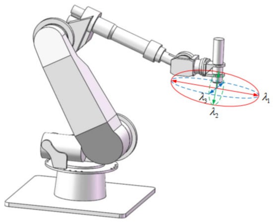
Figure 2.
Force-linear stiffness ellipsoid.
Based on the stiffness ellipsoid and its symmetry, various stiffness indices are designed. In this paper, the omnidirectional index is employed based on the volume of stiffness ellipsoid as follows:
where is the volume of stiffness ellipsoid and can be calculated as follows:
where , and are the eigenvalues of , respectively. and the smaller the , the better the stiffness performance of robot EE.
2.4. Combination of Singularity and Stiffness Indices
The singularity and stiffness indices need to be combined as one scalar index for the following optimal process, where the weighted combination is the most wildly used method. As can be seen from Equations (12) and (13), the value range of is . However, the stiffness of each joint is finite for a real IR. Meanwhile, the volume of the stiffness ellipsoid changes gently at the same tool point with different postures. Therefore, there is a big gap between and in terms of value boundary, change amplitude and order of magnitude. In some tool points, the effect of might be submerged by in a directly weighted combination. Hence, a new stiffness index is proposed in this paper based on as follows:
where and are the maximum and minimum value according to Equation (12) at the same point with different posture. and the smaller the , the batter the overall stiffness performance of the robot EE.
According to Equations (5) and (13), and have same value range and order of magnitude and can be combined with the following form:
where and are the weight factors and belong to . At present, can be selected as the optimization target for the planning of . The smaller the , the batter the performance of robotic milling.
3. Redundant Posture Optimization Based on Piecewise Global Optimization Strategy
3.1. Fundamental of the Piecewise Global Optimization Strategy
The traditional SSPOS is the most commonly used method but is easy to lead to poor optimization effects on subsequent points since only one point is considered in each optimization process. Moreover, due to the displacement constraint of between two adjacent tool points, the optimization process might even fall into a bad region and cannot jump out. Hence, SSPOS is only suitable for the machining process with a single-point operation such as robotic drilling.
The global optimization strategy, which can comprehensively consider all the given tool points, is an effective method to avoid the problems caused by SSPOS. Nevertheless, the quantity of tool points is usually large, which leads to a high computational load for global optimization. Therefore, a piecewise global optimization strategy (PGOS) is proposed, and its flowchart is shown in Figure 3. Firstly, the segmentation is conducted for the given path on the principle of fixed length or fixed-point quantity. Then, globe optimization is employed in each segment until all tool points are optimized, which is introduced in detail in Section 3.2. In particular, the last tool point of the previous segment provides the displacement constraint of for the first point of the next segment.
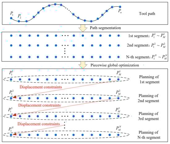
Figure 3.
Procedures of the proposed PGOS.
3.2. Redundant Posture Optimization Method Based on PGOS
Based on PGOS given in Section 3.1, the proposed optimization method can be described as follows with the flowchart shown in Figure 4.
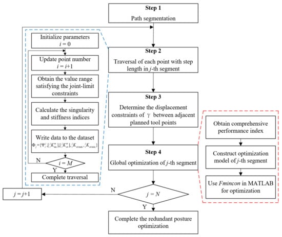
Figure 4.
Redundant posture optimization method based on PGOS.
- Step 1: Path segmentation
The fix point quantity principle is employed to divide the target path into several segments. It is assumed that N segments are generated with M tool points in each segment. Set and go to Step 2.
- Step 2: Traversal of each point with step length in j-th segment.
For i-th point, the initial value range of is . In this range, is set to be the step length for traversal to obtain the critical information. Firstly, the value range of satisfying the joint-limit constraints can be obtained according to Equation (2) and described as the data range .
Secondly, the singularity and stiffness indices of each step in can be calculated according to Equations (5) and (11) and stored into the data sequence and respectively, where denotes the step number. After the traversal of i-th point in j-th segment, the maximum and minimum stiffness indices and in Equation (13) can be obtained from .
When all M points are traversed in j-th segment, the critical data obtained above is stored to the dataset . Then, go to Step 3.
- Step 3: Determination of the displacement constraints of between adjacent planned tool points
The displacement constraint of should be given to limit its variation range between two adjacent planned points. In traditional method, the velocity planning of other five DoFs needs to be executed repeatedly, which is unnecessary and has high computational load. Therefore, a simple method according to the maximum allowable velocity is designed as follows:
where is the position vector, and are the posture coordinate, , , and are the given maximum allowable velocities, respectively. The displacement constraint given in Equation (15) is effective and efficiency without prior velocity planning. In particular, the displacement constraint of should be determined by as shown in Figure 3. Then, go to Step 4.
- Step 4: Globe optimization of j-th segment
For j-th segment, the globe optimization model of M points can be constructed as follows:
where condition C1 can be obtained from dataset , C2 can be determined by Equation (15). During the calculation of according to Equation (14), the performance indices and can be obtained by linear interpolation based on and without complex calculation process, such as the inverse kinematics of robot.
The Fmincon function in MATLAB is employed to conduct the optimization solution where condition C2 is used as the linear inequality constraint. After the optimization of j-th segment, make the following judgment:
If , the redundant posture optimization of the total path is finished;
If , then empty the dataset , and back to Step 2 to conduct the optimization of next segment.
4. Simulation and Validation
In this section, the posture optimization simulation of a complex spatial path is performed to evaluate the good performance of the proposed method. Analysis and comparisons are conducted with the representative method.
4.1. Environment Setup
As shown in Figure 5a, the YASKAWA ES165D serial robot assembled with a high-speed spindle is employed in the simulation and experiments. The Denavit–Hartenberg (D-H) parameters under the modified D-H method are shown in Figure 5b and Table 1. The joint limit parameters are given in Table 2.
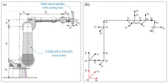
Figure 5.
Robotic milling system. (a) YASKAWA ES165D serial robot with a high-speed spindle. (b) D-H model of robotic milling system.

Table 1.
D-H parameters of ES165D robot.
Table 2.
Joint-limit parameters of ES165D robot.
The joint stiffness of the ES165D robot can be measured and identified by the loading and measuring experiments. The force loaded on the robot EE is measured by a six-dimensional force sensor and the corresponding translational deformation is obtained by the RADIAN Core (API) laser tracker. The stiffness of each joint is illustrated in Table 3.
Table 3.
Joint stiffness of ES165D robot ().
4.2. Simulation Results of Posture Optimization
As shown in Figure 6, the intersecting line constructed by two orthogonal cylindrical surfaces is employed as the test path. And the position and posture relationship between the test intersecting line and the milling robot is shown in Figure 7 where is the workpiece coordinate system. The mathematical expression of intersecting line in is defined as follows:
where , and are the radius of two cylindrical surfaces, respectively. The blue line containing 100 points is the target path of the tool center point (TCP). And the red arrow is the posture of the milling tool. Hence, the coordinate rotating around the red arrow is redundant and needs to be optimized.
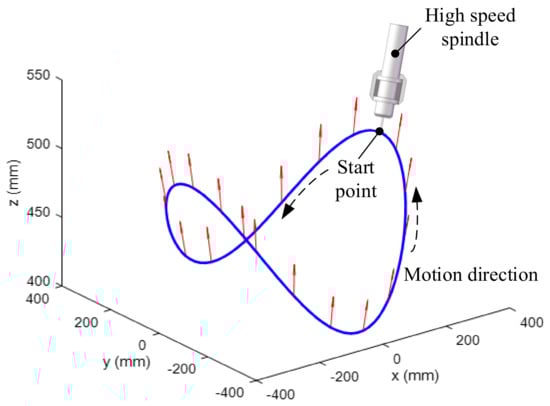
Figure 6.
Test intersecting line.
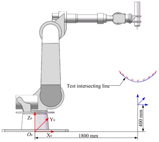
Figure 7.
Pose and posture relationship between the test intersecting line and milling robot.
Based on the performance indices given in Section 2, the comprehensive performance of the robot in each tool point with different postures can be illustrated in Figure 8. The white areas indicate the region of joint-limit, where the corresponding cannot be chosen. In other areas, according to the color bar on the right, the darker the color, the better the comprehensive performance. Therefore, the redundant posture optimization is to obtain a continuous path in Figure 8, which can go through dark areas.
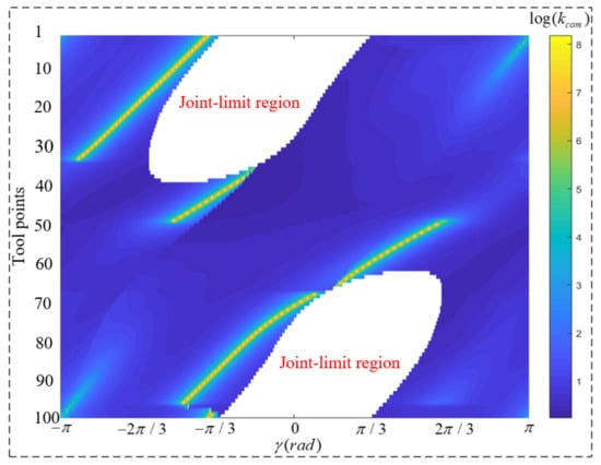
Figure 8.
The comprehensive performance of robot in each tool point with different posture.
As shown in Figure 9a, the optimization results obtained by the traditional SSPOS method are illustrated by the red curve. As can be seen, due to the unreasonable joint-limit judge method, the middle points between the adjacent given tool points might not be able to satisfy the joint-limit constraint, such as the B area, especially when the given tool points have a long distance. Meanwhile, the SSPOS can easily to lead to the gradual deterioration of the optimization process. As can be seen from the A area, the optimization enters the bad area and cannot jump out because of the displacement constraint of between adjacent points. Therefore, the SSPOS has good performance for single-point optimization, such as robotic drilling, but is not suitable for robotic milling with a continuous path.
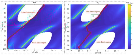
Figure 9.
Optimization results of redundant posture. (a) Result by SSPOS. (b) Result by PGOS.
The optimization results obtained by PGOS are shown in Figure 9b, and the corresponding joint angles are shown in Figure 10. For the first 50 points, the optimization results are similar to SSPOS. The difference is that both the optimized tool points and their middle points in the D area can be guaranteed to satisfy the joint-limit constraints where in Equation (2). It means that the joint-limit constraint strategy given in Equation (2) is a simple and effective scheme, especially for the areas near the joint-limit boundary. For the subsequent 50 points, the PGOS finds the optimal path, which is away from the A area in Figure 9a. Overall, the robot always has a good comprehensive performance by the proposed PGOS.
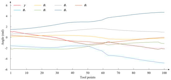
Figure 10.
Optimized and the corresponding joint angles by PGOS.
5. Conclusions
In this paper, a novel redundant posture optimization method is proposed, and the main conclusions are as follows:
- The joint-limit is regarded as a constraint and the singularity and stiffness performances are the optimization target. Correspondingly, the effective and symmetrical judgment method of joint-limit and the performance indices of singularity and stiffness are designed;
- The PGOS is proposed and all the given tool points in their corresponding segment are considered simultaneously. Meanwhile, the computational load of the optimization solution is limited by the designed segmentation strategy;
- As can be seen from the simulation results, the proposed method has better planning quality and can avoid the gradual deterioration caused by SSPOS, which is suitable for the machining process with a continuous path.
Author Contributions
Conceptualization, H.N. and S.J.; methodology, H.N.; software, H.N.; validation, H.N., Y.Y. and S.J.; formal analysis, S.J.; investigation, Y.Y.; resources, S.J.; data curation, H.N.; writing—original draft preparation, H.N.; writing—review and editing, H.N., S.J. and Y.Y.; visualization, S.J.; supervision, S.J.; project administration, S.J.; funding acquisition, S.J. All authors have read and agreed to the published version of the manuscript.
Funding
This work is supported by the Natural Science Foundation of Shandong Province (Grant No. ZR2021QE128, ZR2019QEE042), Major Scientific and Technological Innovation Project of Shandong Province (Grant No. 2022CXGC010101).
Data Availability Statement
All data generated or analyzed during this study are included in this manuscript.
Conflicts of Interest
The authors declare no conflict of interest.
References
- Mikolajczyk, T. Manufacturing using robot. In Advanced Materials Research; Trans Tech Publications Ltd.: Wollerau, Switzerland, 2012; pp. 1643–1646. [Google Scholar]
- Ji, W.; Wang, L. Industrial robotic machining: A review. Int. J. Adv. Manuf. Technol. 2019, 103, 1239–1255. [Google Scholar] [CrossRef]
- Hu, Y.; Chen, Y. Implementation of a robot system for sculptured surface cutting. Part 1. Rough machining. Int. J. Adv. Manuf. Technol. 1999, 15, 624–629. [Google Scholar] [CrossRef]
- Zhu, Z.; Tang, X.; Chen, C.; Peng, F.; Yan, R.; Zhou, L.; Li, Z.; Wu, J. High precision and efficiency robotic milling of complex parts: Challenges, approaches and trends. Chin. J. Aeronaut. 2021, 35, 22–46. [Google Scholar] [CrossRef]
- Huo, L.; Baron, L. The self-adaptation of weights for joint-limits and singularity avoidances of functionally redundant robotic-task. Robot. Comput. Integr. Manuf. 2011, 27, 367–376. [Google Scholar]
- Bigras, P.; Lambert, M.; Perron, C. Robust force controller for industrial robots: Optimal design and real-time implementation on a KUKA robot. IEEE Trans. Control. Syst. Technol. 2012, 20, 473–479. [Google Scholar] [CrossRef]
- Guo, Y.; Dong, H.; Ke, Y. Stiffness-oriented posture optimization in robotic machining applications. Robot. Comput. Integr. Manuf. 2015, 35, 69–76. [Google Scholar] [CrossRef]
- Léger, J.; Angeles, J. Off-line programming of six-axis robots for optimum five-dimensional tasks. Mech. Mach. Theory 2016, 100, 155–169. [Google Scholar]
- Zhang, C.; Ahn, C.K.; Wu, J.; He, W. Online-learning control with weakened saturation response to attitude tracking: A variable learning intensity approach. Aerosp. Sci. Technol. 2021, 117, 106981. [Google Scholar]
- Zhang, C.; Xiao, B.; Wu, J.; Li, B. On low-complexity control design to spacecraft attitude stabilization: An online-learning approach. Aerosp. Sci. Technol. 2021, 110, 106441. [Google Scholar]
- Xie, H.; Li, W.; Yin, Z. Posture optimization based on both joint parameter error and stiffness for robotic milling. In Proceedings of the International Conference on Intelligent Robotics and Applications, Yantai, China, 22–25 October 2021; Springer: Berlin/Heidelberg, Germany, 2018; pp. 277–286. [Google Scholar]
- Peng, J.; Ding, Y.; Zhang, G.; Ding, H. Smoothness-oriented path optimization for robotic milling processes. Sci. China Technol. Sci. 2020, 63, 1751–1763. [Google Scholar] [CrossRef]
- Zhu, W.; Qu, W.; Cao, L.; Yang, D.; Ke, Y. An off-line programming system for robotic drilling in aerospace manufacturing. Int. J. Adv. Manuf. Technol. 2013, 68, 2535–2545. [Google Scholar] [CrossRef]
- Jiao, J.; Tian, W.; Liao, W.; Zhang, L.; Bu, Y. Processing configuration off-line optimization for functionally redundant robotic drilling tasks. Robot. Auton. Syst. 2018, 110, 112–123. [Google Scholar] [CrossRef]
- Bu, Y.; Liao, W.; Tian, W.; Zhang, J.; Zhang, L. Stiffness analysis and optimization in robotic drilling application. Precis. Eng. 2017, 49, 388–400. [Google Scholar] [CrossRef]
- Lin, Y.; Zhao, H.; Ding, H. Posture optimization methodology of 6R industrial robots for machining using performance evaluation indexes. Robot. Comput. Integr. Manuf. 2017, 48, 59–72. [Google Scholar] [CrossRef]
- Dufour, K.; Suleiman, W. On maximizing manipulability index while solving a kinematics task. J. Intell. Robot. Syst. 2020, 100, 3–13. [Google Scholar] [CrossRef]
- Li, Y.; Yang, X.; Wu, H.; Chen, B. Optimal design of a six-axis vibration isolator via Stewart platform by using homogeneous Jacobian matrix formulation based on dual quaternions. J. Mech. Sci. Technol. 2018, 32, 11–19. [Google Scholar] [CrossRef]
- Li, G.; Zhu, W.; Dong, H.; Ke, Y. Stiffness-oriented performance indices defined on two-dimensional manifold for 6-DOF industrial robot. Robot. Comput. Integr. Manuf. 2021, 68, 102076. [Google Scholar] [CrossRef]
- Yin, B.; Wenhe, L.; Wei, T.; Zhang, L.; Dawei, L. Modeling and experimental investigation of Cartesian compliance characterization for drilling robot. Int. J. Adv. Manuf. Technol. 2017, 91, 3253–3264. [Google Scholar]
- Mikolajczyk, T. System to surface control in robot machining. In Advanced Materials Research; Trans Tech Publications Ltd.: Wollerau, Switzerland, 2012; pp. 708–711. [Google Scholar]
- Chen, C.; Peng, F.; Yan, R.; Li, Y.; Wei, D.; Fan, Z.; Tang, X.; Zhu, Z. Stiffness performance index based posture and feed orientation optimization in robotic milling process. Robot. Comput. Integr. Manuf. 2019, 55, 29–40. [Google Scholar] [CrossRef]
- Xiong, G.; Ding, Y.; Zhu, L. A feed-direction stiffness based trajectory optimization method for a milling robot. In Proceedings of the International Conference on Intelligent Robotics and Applications, Wuhan, China, 16–18 August 2017; Springer: Berlin/Heidelberg, Germany, 2017; pp. 184–195. [Google Scholar]
- Xiong, G.; Ding, Y.; Zhu, L. Stiffness-based pose optimization of an industrial robot for five-axis milling. Robot. Comput. Integr. Manuf. 2019, 55, 19–28. [Google Scholar] [CrossRef]
- Liao, Z.; Li, J.R.; Xie, H.; Wang, Q.; Zhou, X. Region-based toolpath generation for robotic milling of freeform surfaces with stiffness optimization. Robot. Comput. Integr. Manuf. 2020, 64, 101953. [Google Scholar] [CrossRef]


Publisher’s Note: MDPI stays neutral with regard to jurisdictional claims in published maps and institutional affiliations. |
© 2022 by the authors. Licensee MDPI, Basel, Switzerland. This article is an open access article distributed under the terms and conditions of the Creative Commons Attribution (CC BY) license (https://creativecommons.org/licenses/by/4.0/).