Article

Accurate Analytical Models of Armature Reaction Field for Multi-Segment Primaries Ironless PMLSM Based on Subdomain Method

School of Mechanical and Electrical Engineering, Wuhan University of Technology, Wuhan 430070, China
*
Author to whom correspondence should be addressed.
Symmetry 2022, 14(10), 2091; https://doi.org/10.3390/sym14102091
Submission received: 25 August 2022 / Revised: 23 September 2022 / Accepted: 6 October 2022 / Published: 8 October 2022

Abstract

:
Multi-segment-primary (MSP) ironless Permanent Magnet Linear Synchronous Machine (PMLSM) can be widely applied in long primary, long stroke, and heavy load applications. Therefore, an accurate armature reaction field analysis is very important to control this novel topology motor. In order to simplify the research process, a two-segment-primary (TSP) ironless PMLSM in this article was proposed as the smallest unit. The analytical models of the armature reaction field of the motor based on the subdomain method (SDM) were established considering the finite length of the segment-primary (SP) and the interval distance between the TSP. Then, the coupling effect between the TSP and the end effect of the TSP on the armature reaction field were quantitatively analyzed. Furthermore, the coupling inductance between the TSP can be analytically calculated, which is influenced by the coupling effect. To validate the effectiveness of the proposed models, a prototype of the 24s/28p TSP ironless PMLSM was manufactured and tested. It was shown that the proposed models match well with the simulated and experimental results. As well, the maximum variation rate of the end coupling inductance was about 50.13%.

1. Introduction

Different from a traditional PMLSM with one SP, the PMLSM with MPS has attracted some scholars’ extensive attention. This segmented design can simplify the motor assembly process, facilitate the flexible expansion of the SP number and reduce thrust fluctuations [1,2,3,4,5]. Meanwhile, the segmented design can isolate the winding magnetic circuit coupling and improve the inductance asymmetry [6]. Besides, for the naturally air-cooled PMLSM, the air spacing between the adjacent SP can improve the heat dissipation performance of the whole motor [7]. Consequently, the multi-segment PMLSM can be widely apd in the long primary, long stroke, and heavy load applications [8,9,10].
Currently, for the SP topology, most researchers focus on how to reduce the detent force of the iron core PMLSM. In [11], a mover with three-segment has been proposed to suppress the detent force of the linear motor with a long armature stator. In [12], the effect of “E-shape” and “C-shape” SP of iron core PMLSM on the whole motor detent force are compared and analyzed, respectively. But they only investigate the slotted iron core PMLSM. The slotless tubular PMLSM with three sectional primaries and flux barrier distances are analyzed to suppress the whole motor detent force [13,14]. In order to further improve the thrust density in [13,14], the module tubular PMLSM with a large slot structure is proposed in [15]. Further, in [16], the influence of the coupling effect between the adjacent SP on the PMLSM detent force is carried out by Schwarz–Christoffel (SC) transformation. In a word, the modular design described above has been mainly to reduce the iron core PMLSM detent force. Whereas, for the MSP ironless PMLSM, there are no relative research reports.
As the MSP ironless PMLSM has no cogging force and detent force, it can be widely used in high-precision, long-stroke movement. Traditionally, it is ideally seen that the SP is independent of each other due to the air flux barrier between the adjacent SP. In fact, there is still a certain degree of coupling effect between the adjacent SP and the end effect of the SP end. The coupling effect and end effect can impact the precise control of the MSP ironless PMLSM. Therefore, an accurate approach is essential to evaluate the influence of the coupling effect and end effect on the whole motor.
The SDM is used to divide the electromagnetic field into several regions [17,18]. Then, this approach can realize a high degree of calculation accuracy by employing Poisson or Laplace equations in each region combined with boundary conditions [19,20]. The magnetic field generated by armature windings is influenced by the coupling effect and end effect. Therefore, the main objective of this research is to establish accurate analytical models of MSP for predicting the armature reaction field by the SDM. Further, the armature reaction field can be used to derive self- and mutual inductances. Accurate inductances are essential to achieve high-precision control of the MSP ironless PMLSM.
The existing study of the armature reaction of the ironless PMLSM mainly focuses on one SP. In [21], for the ironless PMLSM with double-layer asymmetric windings, a “virtual periodic primary” is applied to calculate the armature reaction field by the SDM. The analytical model assumes that the distance between adjacent primaries is so large that the coupling effect can be neglected. In [22,23,24,25], the armature reaction of the PMLSM is calculated by the SDM and the inductance of the PMLSM can be derived by the magnetic energy method. Obviously, a single SP cannot take into account the coupling effect among MSP and the end effect of MSP, which can influence the armature reaction field and inductance of the MSP ironless PMLSM. To simplify the research process, a TSP ironless PMLSM is taken as the smallest unit to study the coupling effect and end effect. By establishing the accurate analytical models with the finite length of the TSP, the coupling effect and end effect on the armature reaction field and inductance can be quantitatively analyzed.
The main contributions of this article are listed as follows:
(1)
The analytical model can quantitatively analyze the coupling effect and end effect on the armature reaction field. Therefore, the accurate armature reaction field of the TSP ironless PMLSM in the initial design stage can be rapidly obtained.
(2)
The accurate analytical models of the armature reaction field can be used to derive inductances, which facilitate the high-precision control of the TSP ironless PMLSM.

2. Motor Structure and Armature Winding Current Modeling

This article takes a 24s/28p TSP ironless PMLSM as a case to analyze. Figure 1 shows the structure of the motor, which includes TSP, two rows of PMs, upper and lower back irons. Meanwhile, Figure 1 represents the subdomain model of the motor in an x-y coordinate system, which is divided into three regions. The main structural specifications of the motor are listed in Table 1. As for the interval distance between the TSP, it can be adjustable according to practical application. For the fractional slot windings of the TSP, the spatial arrangement of armature windings of one SP is shown in Figure 1 with “12s/14p”. The winding arrangement of the other SP is identical. This can meet the requirement of flexible stroke and a larger load by adding the number of SP.
For the TSP ironless PMLSM, the primary of the motor is non-magnetizing materials except for armature windings. As well, the relative permeability of non-magnetizing materials is equal to 1. In order to take into account the winding end effect, the starting point of the global coordinate is set 10 mm apart from segment I based on the FEM results. Meanwhile, considering the interval distance between the TSP, current modeling is required for all coils of the motor. It is assumed that the armature winding current flowing in is the positive direction and out is the negative direction.
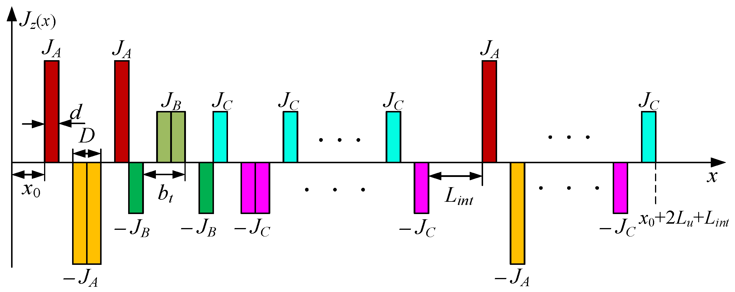
At some moment, if the three-phase instantaneous current IA = −2IB = −2IC, the winding current density distribution is shown in Figure 2.
From Figure 2, the current density expression in each virtual slot at any time can be written as
J A 1 z Seg   I ( x ) = { J A ,   x 0 x x 0 + d 0 ,   e l s e w h e r e
J A 2 z Seg   I ( x ) = { J A ,   x 0 + b t d x x 0 + b t 0 ,   e l s e w h e r e
J A 3 z Seg   I ( x ) = { J A ,   x 0 + b t x x 0 + b t + d 0 ,   e l s e w h e r e
J i 2 Q z Seg   II ( x ) = { J i ,   x 0 + Q b t + L int d x x 0 + Q b t + L int 0 ,   e l s e w h e r e
where x is the horizontal coordinate of each coil side. J i 2 Q z Seg   II (x) (i = A, B, C) is the ith phase current density function of the Qth (Q = 13, 14,…, 24) virtual slot coil side of the segment II.
The three-phase current density Ji can be expressed as
{ J A = N S I m sin ( 2 π f t ) / ( h c d ) J B = N S I m sin ( 2 π f t 2 π 3 ) / ( h c d ) J C = N S I m sin ( 2 π f t + 2 π 3 ) / ( h c d )
f = v / 2 τ
Since the current density in the virtual slot is periodically distributed, the current density of phases A, B, and C can be expanded into the Fourier series as follows:
{ J A z ( x ) = n = 1 b n A sin k n ( x x 0 ) J B z ( x ) = n = 1 b n B sin k n ( x x 0 2 b t ) J C z ( x ) = n = 1 b n C sin k n ( x x 0 4 b t )
k n = 2 n π τ e
τ e = x 0 + 2 L u + L int
where n is the harmonic order. τe is the periodic distribution distance of armature windings in the x-axis.
The Fourier coefficients bnA, bnB, and bnC can be written as
{ b n A = 2 τ e 0 τ e J A 2 Q z SegI , SegII ( x ) sin k n ( x x 0 ) d x b n B = 2 τ e 0 τ e J B 2 Q z SegI , SegII ( x ) sin k n ( x x 0 2 b t ) d x b n C = 2 τ e 0 τ e J C 2 Q z SegI , SegII ( x ) sin k n ( x x 0 4 b t ) d x

3. Analytical Solutions of Armature Reaction Field

Due to the regular shape of the subdomain region shown in Figure 1, the analytical models of the armature reaction field of the motor can be precisely established by the SDM. To simplify the analytical models, assumptions are made as follows:
(1) PMs are not magnetized; (2) the permeability of back iron is infinite; (3) neglecting the transverse end effect; (4) the relative permeability of PMs is equal to 1 and the secondary extends infinitely in the x-axis direction.

3.1. Governing Equations

As shown in Figure 1, the field domain is divided into three regions: (1) region I–armature windings; (2) region II–the lower air-gap and PMs; (3) region III–the upper air-gap and PMs. Since the transverse end effect is neglected, the magnetic vector potential Aiz and current density Jiz(x) only have a z-axis component. Based on the Maxwell equation, the governing field equation in the three regions can be written as
2 A i z x 2 + 2 A i z y 2 = { μ 0 J i z ( x )   in   R e g i o n   I 0   in   R e g i o n   I I   and   R e g i o n   I I I
where Aiz is the z-axis magnetic vector potential of the ith phase, μ0 is the vacuum permeability, and Jiz(x) is the z-axis current density of the ith phase.
By the method of separation of variables, general solutions of the Laplace equation and the Poisson equation in each phase can be derived as
{ A i z I = n = 1 ( A n i e k n y k n + A n i e k n y k n + μ 0 J n j ) sin k n ( x D i ) A i z I I = n = 1 ( B n i k n e k n y + B n i k n e k n y ) sin k n ( x D i ) A i z I I I = n = 1 ( C n i k n e k n y + C n i k n e k n y ) sin k n ( x D i )
{ D A = x 0 D B = x 0 + 2 b t D C = x 0 + 4 b t
where Jnj = bnj/ k n 2 (j = A, B, C) is the coefficient of general solutions. Ani, Ani, Bni, Bni, Cni, and Cni are unknown coefficients of the three-region, which can be determined by boundary conditions.

3.2. Boundary Conditions

Due to the continuous interface of each region, boundary conditions are determined. To acquire the above six unknown coefficients, six boundary conditions of each phase are given as
{ y 1 = 0 ,   H i x I I = 0 y 2 = h m + δ 2 ,   B i x I = B i x I I   B i y I = B i y I I y 3 = h m + δ 2 + h c ,   B i x I = B i x I I I   B i y I = B i y I I I y 4 = 2 h m + δ 1 + δ 2 + h c , H i x I I I = 0

3.3. Final Results

By calculating the partial derivatives of magnetic vector potential Aiz, the normal (y-axis) and tangential (x-axis) flux density of the ith phase in each region can be given by
B i x = A i z y   ,   B i y = A i z x
For the ith phase, the magnetic field density in the three-region is expressed as
{ B i x I = n = 1 ( A n i e k n y A n i e k n y ) sin k n ( x D i ) B i y I = n = 1 ( A n i e k n y + A n i e k n y + μ 0 k n J n j ) cos k n ( x D i ) B i x I I = n = 1 ( B n i e k n y B n i e k n y ) sin k n ( x D i ) B i y I I = n = 1 ( B n i e k n y + B n i e k n y ) cos k n ( x D i ) B i x I I I = n = 1 ( C n i e k n y C n i e k n y ) sin k n ( x D i ) B i y I I I = n = 1 ( C n i e k n y + C n i e k n y ) cos k n ( x D i )
Since the flux density is a vector, the flux density of the three-phase satisfies the superposition principle of each phase. Therefore, the flux density in each region can be expressed as
{ B x I , I I , I I I = B A x I , I I , I I I + B B x I , I I , I I I + B C x I , I I , I I I B y I , I I , I I I = B A y I , I I , I I I + B B y I , I I , I I I + B C y I , I I , I I I  
By employing the boundary conditions of each region, the nth harmonic coefficient expression of the three-phase can be obtained by MATLAB program.

4. Inductance Calculation

For the TSP ironless PMLSM, the exact inductance is the basis for the mathematical model of the motor control system. Since the analytical model of the armature reaction field of the motor includes the end effect and coupling effect, the self- and mutual inductance of the motor can be accurately calculated by the magnetic energy method. When calculating the inductance, only the magnetic energy from armature windings is required.
The magnetic energy in the current region can be expressed as [23]
W = 1 2 V J i z A i z d V
where V is the current region volume.
Further, the magnetic energy of each phase of windings and two-phase windings in the current region I can be simplified as
W i j = { L e f 2 n = 1 δ 2 δ 2 + h c 0 L A i z I J i z d x d y   i = j   L e f 2 n = 1 δ 2 δ 2 + h c 0 L ( A i z I J i z + A j z I J j z ) d x d y   i j  
where i and j represent phase A, phase B, and phase C, respectively. Wii is the magnetic energy when the motor has only the ith phase current. Wij is the magnetic energy when the motor has both the ith phase and jth phase currents.
Therefore, the self- and mutual inductance can be derived as [24]
L i i = 2 W i i I i 2 ,   M i j = ( W i j W i W j ) / ( I i I j )
where Lii is the self-inductance of the ith phase. Mij is the mutual inductance between the ith phase and the jth phase. Ii and Ij are instantaneous currents of the ith phase and jth phase, respectively.

5. FEM, Analytical, and Experiment Verification

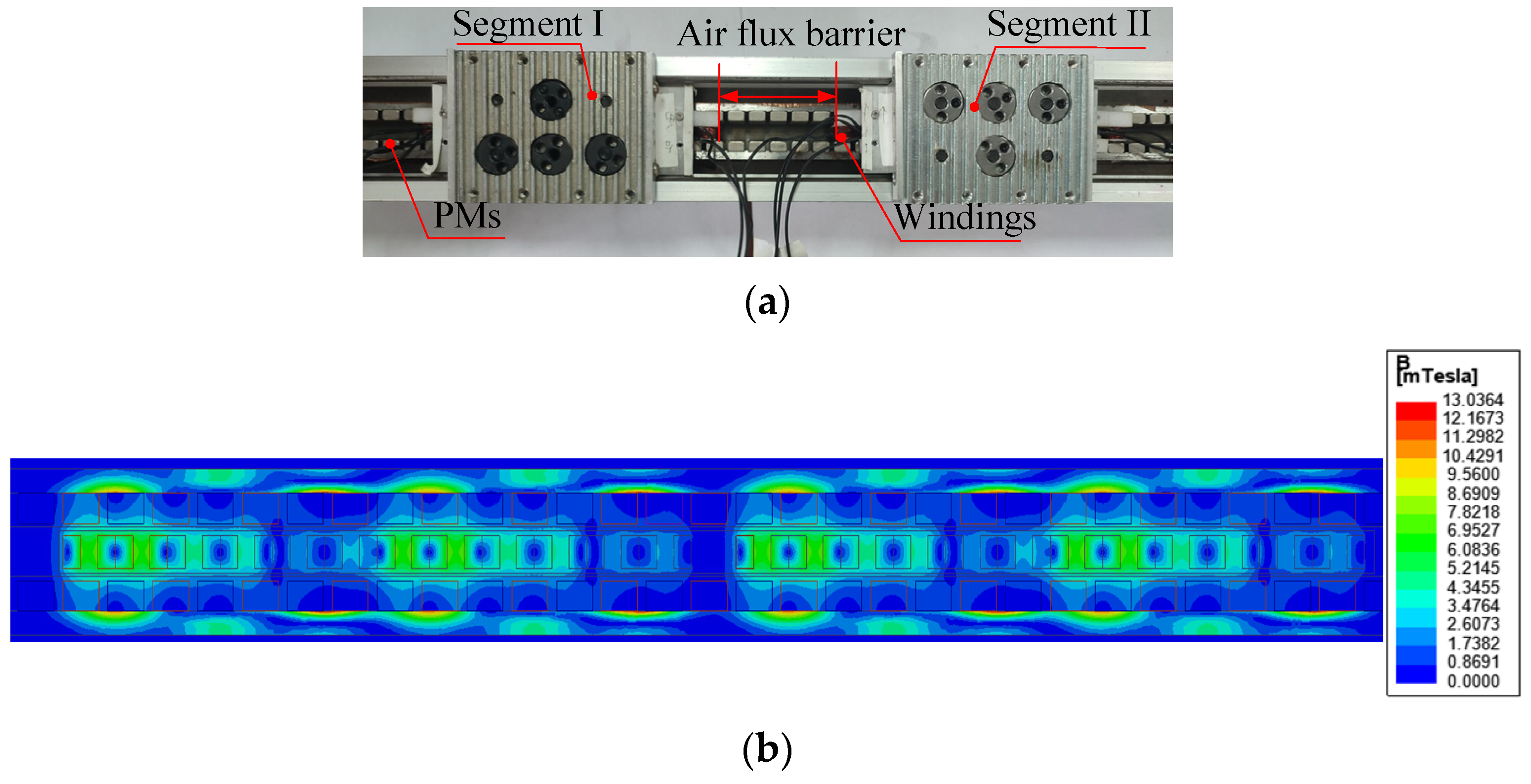
Figure 3a shows a photograph of the 24s/28p TSP ironless PMLSM to confirm the validity of analytical solutions and FEM results. The armature reaction field distribution simulated by FEM is shown in Figure 3b. The simulated peak value and frequency of three-phase sinusoidal currents are 1 A and 1.5 Hz in this section, respectively. As shown in Figure 3b, the maximum flux density in each region is less than 10 mT, which cannot occur during magnetic saturation. Therefore, it is reasonable to linearly superimpose the magnetic field generated by the three-phase windings in Section 3.
The measurement platform of winding inductance is performed under the condition without PMs excitation, as shown in Figure 4a. The test procedure is mainly based on the method in [23]. The model of the LCR meter is TH2822D and its measuring accuracy is 0.1%. The model of the multimeter is UT61E+ and its measuring accuracy is 0.05%. There are two steps to measure the inductance. The first step is to measure the self-inductance, which can be directly acquired by the LCR meter at different frequencies. The second step is to measure mutual inductance. A sampling resistance (1K 0.1%) is connected in series with one phase. Meanwhile, this phase is provided with a certain frequency sinusoidal current (10 KHz) by the LCR meter. Then, the multimeter is employed to record the other phase-induced voltage and this resistance terminal voltage. Besides, the interval distance between the TSP is adjusted by a micrometer.
I i = V s a m p l e R s a m p l e
M i j = E j 2 π f I i
where Ii is the ith phase current. f is the ith phase current frequency. Ej is the other phase inductance voltage. Mij is the ith and jth phase of mutual inductance.
Figure 4b shows the experimental platform on the armature reaction field of the TSP ironless PMLSM. Three DC power supplies (UTP3313TFL-II and MS-305D) are used to provide currents for three-phase windings. The three-phase currents at different times are obtained by adjusting the magnitudes of the three DC currents. The values of three-phase currents are the same as the FEM current settings. The model of the Gauss meter is SJ700 and its resolution is 0.01 mT, which can meet the measurement for precision. As shown in Figure 1, region II and region III have the same air-gap flux density. Therefore, we employ the Gauss meter to record the lower air-gap flux density in region II. Besides, the flux density between the TSP region is also measured. The position of the flux density is defined by the micrometer and the interval distance between the TSP is adjusted by the micrometer.
In order to compare with the ideal conditions of analytical models in Section 3, the FEM setting conditions based on the actual motor material in this section are listed as follows. The simulated software is Maxwell. The material of the back iron is Q235, which the relative permeability is set as 4000. Meanwhile, the PM relative permeability is set as 1.05.

5.1. Armature Reaction Field Validation without Coupling Effect

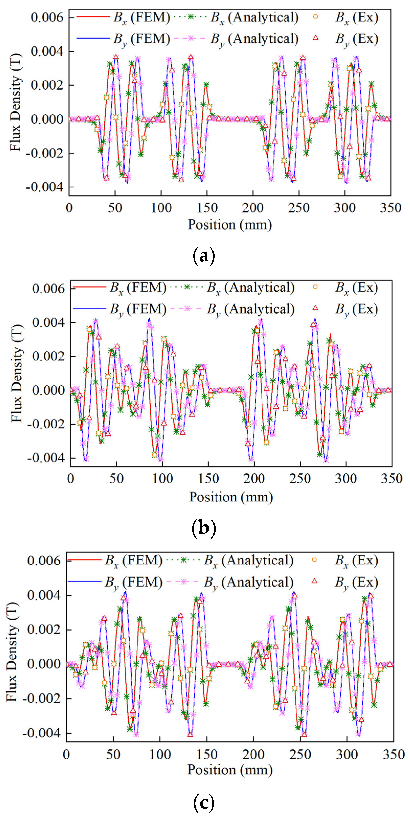
When the interval distance between the TSP is large enough, there is no coupling effect between the TSP. The interval distance is set to 4τ (40 mm) in this subsection. Since the three-phase currents vary periodically, it is necessary to compare the flux density of the experiment, FEM, and analytical modeling within a half electrical period. The half electrical period is divided into two time intervals (t = 0 s, 0.15 s, and 0.3 s). The middle position of the lower air-gap region II (y = 5.8 mm) is selected to verify the validity of the proposed analytical model. Figure 5 shows that the air-gap flux density distribution of the middle position of the lower air-gap region at three different times. It can be found that analytical results agree well with FEM and experiment results. Meanwhile, segment I and segment II have the same air-gap flux density distribution in the x and y direction. This also verifies that the 40 mm interval distance is large enough without occurring the coupling effect. As seen, the armature reaction field is relatively small due to lacking the iron core primary. Therefore, it requires higher accuracy of the analytical model.
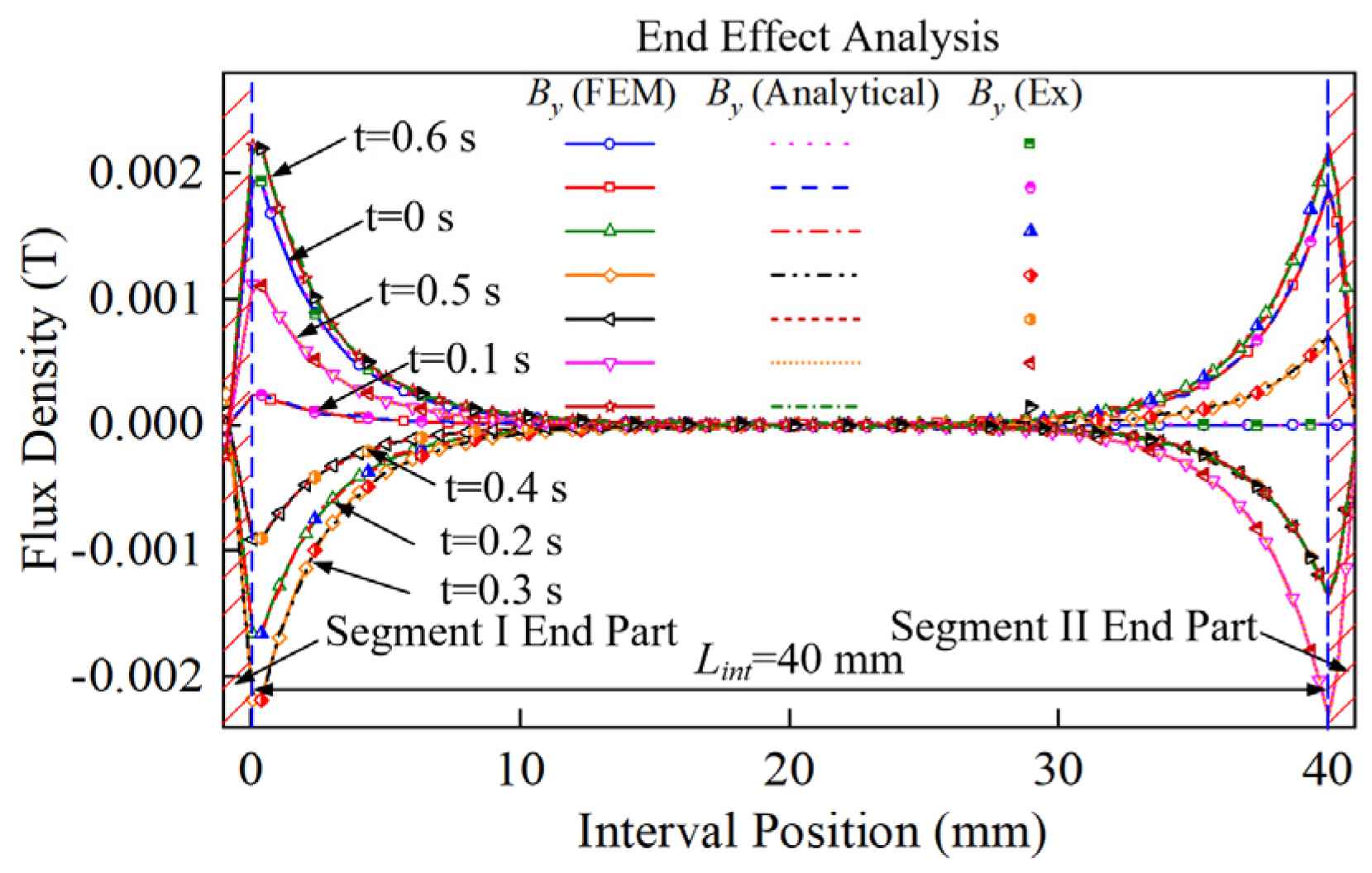
Meanwhile, considering the finite length analytical model of the TSP, the end magnetic field distribution between the TSP can also be calculated. The middle position of region I between the TSP (y = 9.7 mm) is selected to calculate the flux density. Because the flux line in the middle position of this region is perpendicular to the x-axis, only exists the y-axis flux density. Figure 6 reveals that the normal flux density varies exponentially with position during the full electrical cycle, which is divided into six time intervals (t = 0 s, 0.1 s, 0.2 s, 0.3 s, 0.4 s, 0.5 s, and 0.6 s). As seen above, the analytical results are well consistent with the FEM and experimental results between the TSP region. The end flux density quickly decreases to 0 T, which the influence range is about 10 mm.

5.2. Armature Reaction Field Validation with Coupling Effect

In the case of the uncoupled effect, the end flux density distribution between the TSP and the air-gap flux density distribution of the TSP have been investigated in Section 5.1. However, the end coupling effect may occur when the TSP gets closer. This can lead to the flux density asymmetry of the TSP. Therefore, it is necessary to explore the influence of different interval distances on the coupling effect.
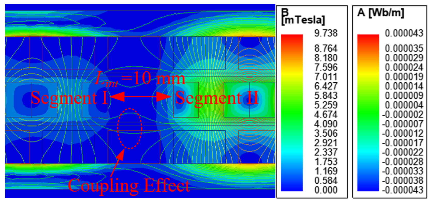
Firstly, the magnetic flux line distribution at the end of the TSP is obtained by FEM shown in Figure 7. The interval distance is 10 mm and the 2-D contour map displays at the 0.15 s moment. As seen, the magnetic flux line between the TSP ends affects each other. Meanwhile, the coupling effect within the interval distance Lint = 10 mm is investigated in this subsection.
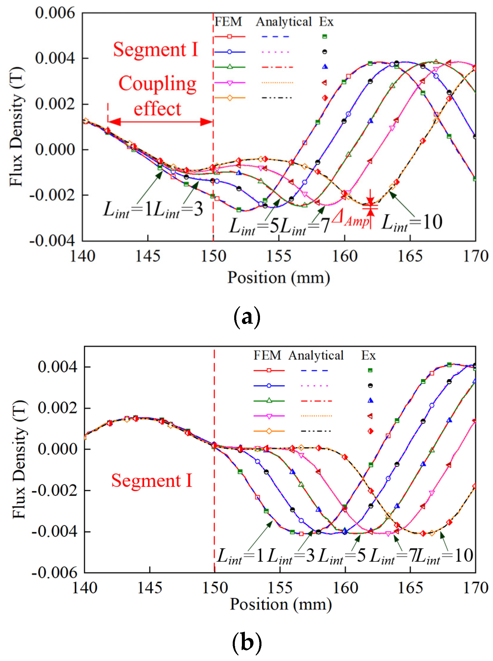
Figure 8a shows that the tangential air-gap flux density distribution curves differ with different interval distances in the middle position of the lower air-gap region II. When the interval distance is smaller, the amplitude of the tangential air-gap flux density varies more. The amplitude of the tangential air-gap flux density between Lint = 1 mm and Lint = 10 mm differs about 0.28 mT, and the rate of variation in magnitude is about 11.6%. Besides, the depth of the segment I tangential air-gap flux density affected by the coupling effect is about 5–10 mm. Owing to the coupling effect, the tangential air-gap flux density generated by the TSP becomes asymmetrical. However, as shown in Figure 8b, the normal air-gap flux density distribution curves are basically the same with different interval distances in the middle position of the lower air-gap region II. Variations of amplitudes in various interval distances are basically identical. The coupling effect has little influence on the normal air-gap flux density. The analytical results in region II match well with the FEM and test results.
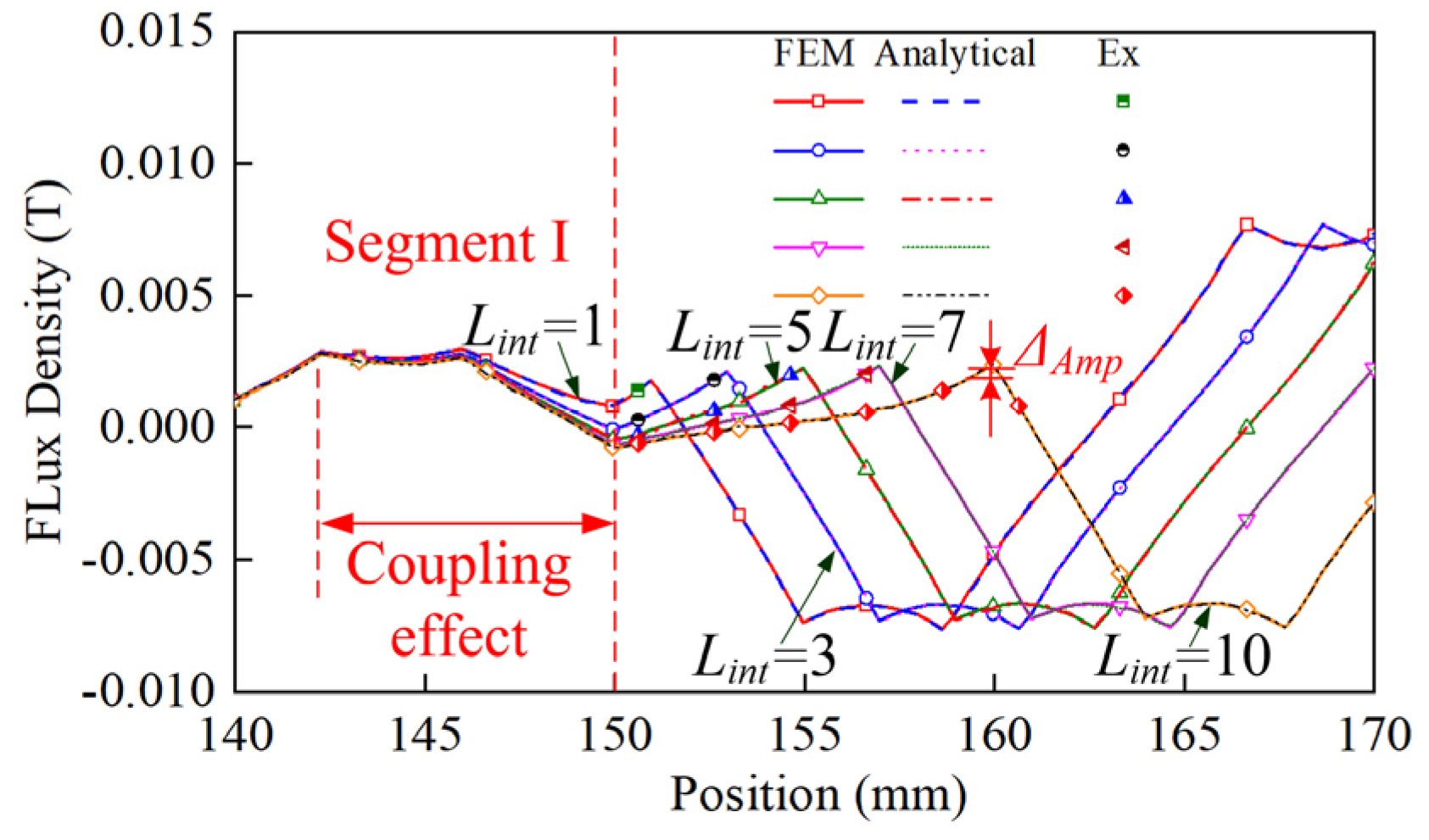
The normal flux density distribution curves differ with different interval distances in the middle position of the armature winding region I between the TSP, as shown in Figure 9. The amplitude of the normal flux density between Lint = 1 mm and Lint = 10 mm differs about 0.33 mT, and the rate of variation in magnitude is about 18.7%. Besides, the depth of the segment I normal flux density in region I affected by the coupling effect is about 5–10 mm. Therefore, when the size of the primary is smaller, the influence of the coupling effect can be more obvious. Meanwhile, the analytical results in region I agree well with the FEM and measured results. As seen from Figure 5 to Figure 6, the coupling effect is negligible when the interval distance is larger than 20 mm.

5.3. Comparisons of Inductance Calculation with FEM, Analytical, and Experiment

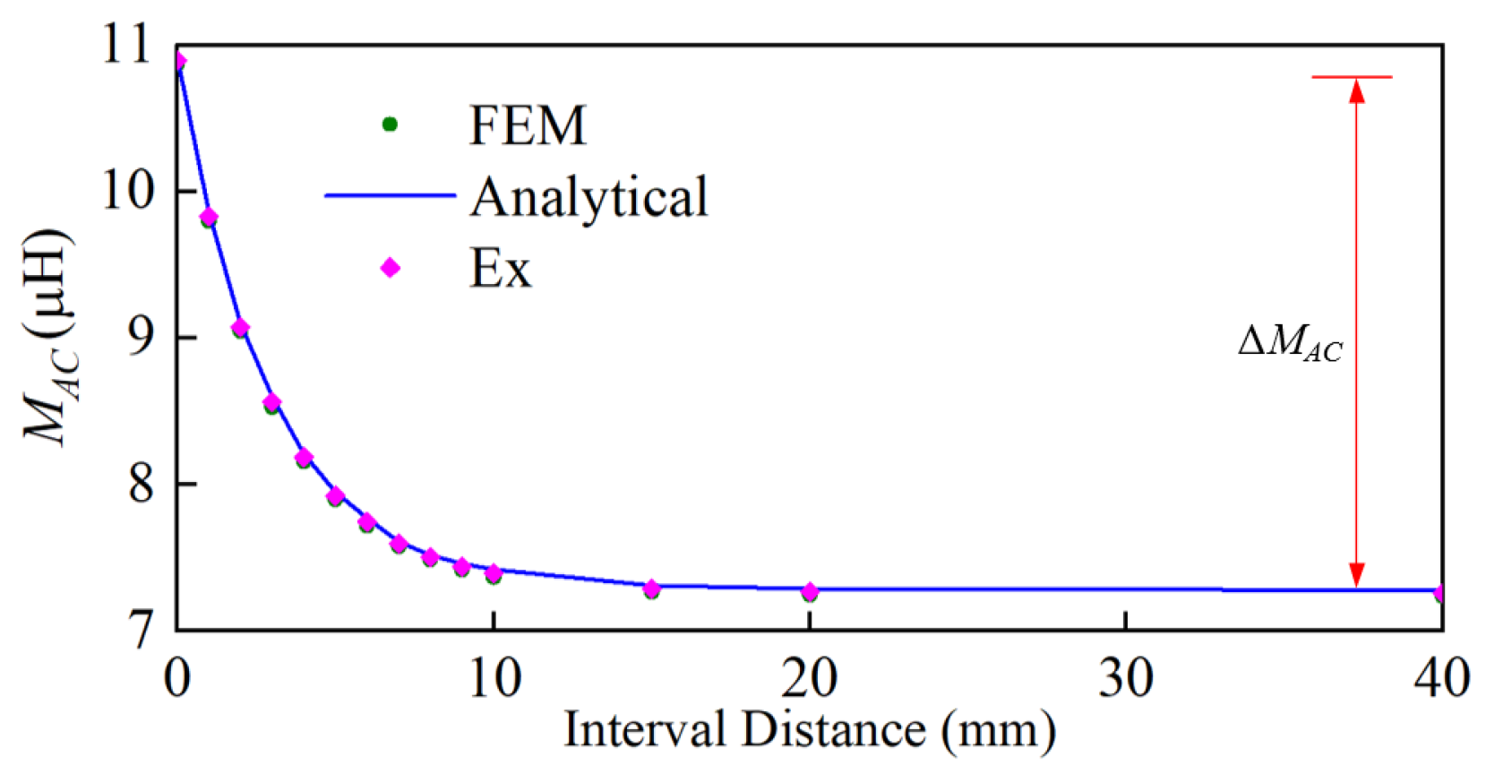
According to Equations (16)–(19), the coupling inductance can be calculated. The results of inductance without coupling effect obtained by the FEM, analytical, and experiment are presented in Table 2. The errors among them are relatively small. Further, according to the conclusions in Section 5.2, the coupling effect only affects the mutual inductance of MAC and has almost no effect on other inductances owing to the depth of the coupling effect. As seen in Figure 10 and Table 3, the end coupling inductance of MAC affected by coupling inductance decreases exponentially with the interval distance. The average value of MAC decreases from 10.90 μH to 7.26 μH, and the rate of change is about 50.13%. Influenced by the coil size in the motor, the end coupling inductance is relatively small. However, for the large power MSP ironless PMLSM, the coupling inductance can be larger.

6. Conclusions

The MSP ironless PMLSM has the merits of simplifying the manufacturing process and facilitating heat dissipation. To simplify the research, a TSP ironless PMLSM was investigated in this article. Based on the SDM, accurate analytical models of the motor considering the coupling effect and end effect were established. Then, the prototype was built and tested. The proposed analytical models agree well with the FEM and experiment results. Based on the results, the conclusions can be listed as follows:
(1)
When the interval distance was greater than 40 mm, there was no coupling effect between the TSP. Meanwhile, the end flux density of the TSP varied exponentially with the position.
(2)
When the interval distance was less than 40 mm, there existed a coupling effect especially in 0–10 mm. The coupling effect can influence the tangential air-gap flux density and normal flux density between the TSP. Whereas, the normal air-gap flux density cannot be affected by the coupling effect.
(3)
Influenced by the coupling effect, the maximum change rate of the end coupling inductance was about 50.13%. The end coupling inductance varied exponentially with interval distance.
This study can be used to design and control the ironless PMLSM with any number of SP.

Author Contributions

Conceptualization, F.Z. and H.Y.; methodology, F.Z.; software, F.Z.; validation, F.Z., and H.Y.; formal analysis, F.Z.; investigation, F.Z.; resources, H.Y.; data curation, F.Z.; writing—original draft preparation, F.Z.; writing—review and editing, H.Y. and Y.L.; visualization, F.Z.; supervision, H.Y. All authors have read and agreed to the published version of the manuscript.

Funding

This research received no external funding.

Institutional Review Board Statement

Not applicable.

Informed Consent Statement

Not applicable.

Data Availability Statement

Not applicable.

Conflicts of Interest

The authors declare no conflict of interest.

References

  1. Li, J.; Huang, X.; Zhou, B.; Liu, Y.S.; Huang, Q. Design Criterion for Dual-Modular Permanent Magnet Linear Synchronous Motor With Long Stroke and High Flexibility. IEEE Trans. Ind. Electron. 2022, 69, 10428–10436. [Google Scholar] [CrossRef]
  2. Jiang, Q.; Lu, Q. Performance Investigation of a five-phase Multi-segment primary PMLSM for Ropeless Elevator. In Proceedings of the 2018 IEEE International Magnetic Conference (INTERMAG), Singapore, 23–27 April 2018. [Google Scholar] [CrossRef]
  3. Chung, S.-U.; Lee, H.-J.; Woo, B.-C.; Kim, J.-W.; Lee, J.-Y.; Moon, S.-R.; Hwang, S.-M. A Feasibility Study on a New Doubly Salient Permanent Magnet Linear Synchronous Machine. IEEE Trans. Magn. 2010, 46, 1572–1575. [Google Scholar] [CrossRef]
  4. Chung, S.-U.; Kim, J.-W.; Woo, B.-C.; Hong, D.-K.; Lee, J.-Y.; Koo, D.-H. Force Ripple and Magnetic Unbalance Reduction Design for Doubly Salient Permanent Magnet Linear Synchronous Motor. IEEE Trans. Magn. 2011, 47, 4207–4210. [Google Scholar] [CrossRef]
  5. Yan, L.; Li, W.; Jiao, Z.; Hu, H.; Chen, C.-Y.; Chen, I.M. Design and Modeling of Tubular Flux-Switching Permanent Magnet Linear Motor. In Proceedings of the 2014 IEEE Chinese Guidance, Navigation and Control Conference (CGNCC), Yantai, China, 8–10 August 2014; pp. 2799–2804. [Google Scholar]
  6. Bai, Y.; Yang, T.; Kou, B. Reducing Detent Force and Three-phase Magnetic Paths Unbalance of PM Linear Synchronous Motor Using Modular Primary Iron-Core Structure. In Proceedings of the 2014 17th International Conference on Electrical Machines and Systems (ICEMS), Hangzhou, China, 22–25 October 2014; pp. 1743–1748. [Google Scholar]
  7. Lu, Q.; Huang, L.; Ye, Y.; Huang, X.; Fang, Y. Design of a novel permanent magnet linear synchronous motor with segmented armature core for ropeless lifter. COMPEL Int. J. Comput. Math. Electr. Electron. Eng. 2016, 35, 556–571. [Google Scholar] [CrossRef]
  8. Fan, H.; Chau, K.T.; Liu, C.; Cao, L.; Ching, T.W. Quantitative Comparison of Novel Dual-PM Linear Motors for Ropeless Elevator System. IEEE Trans. Magn. 2018, 54, 8106506. [Google Scholar] [CrossRef]
  9. Lv, G.; Zeng, D.; Zhou, T.; Liu, Z. Investigation of Forces and Secondary Losses in Linear Induction Motor With the Solid and Laminated Back Iron Secondary for Metro. IEEE Trans. Ind. Electron. 2017, 64, 4382–4390. [Google Scholar] [CrossRef]
  10. Li, J.; Huang, X.; Zhou, B.; Liu, Y.; Wang, Z. Research on Segmented Primary Consequent-Pole Permanent Magnet Linear Synchronous Motor with Symmetric and Periodic End Force. Symmetry 2021, 13, 2374. [Google Scholar] [CrossRef]
  11. Tan, Q.; Li, L.; Huang, X.; Wang, M.; Yang, R. Analysis of the Detent Force for the Long-Stator Permanent Magnet Linear Synchronous Motor with Modular Mover. In Proceedings of the 2018 21st International Conference on Electrical Machines and Systems (ICEMS), Jeju, Korea, 7–10 October 2018; pp. 1853–1856. [Google Scholar]
  12. Yao, Y.; Lu, Q. Comparative Study of E-Core and C-Core Modular PM Linear Machines With Different Slot/Pole Combinations. IEEE Trans. Magn. 2017, 53, 8110307. [Google Scholar] [CrossRef]
  13. Huang, X.Z.; Li, J.; Tan, Q.; Qian, Z.Y.; Zhang, C.; Li, L. Sectional Combinations of the Modular Tubular Permanent Magnet Linear Motor and the Optimization Design. IEEE Trans. Ind. Electron. 2018, 65, 9658–9667. [Google Scholar] [CrossRef]
  14. Huang, X.Z.; Li, J.; Tan, Q.; Zhang, C.M.; Li, L. Design Principles of a Phase-Shift Modular Slotless Tubular Permanent Magnet Linear Synchronous Motor With Three Sectional Primaries and Analysis of Its Detent Force. IEEE Trans. Ind. Electron. 2018, 65, 9346–9355. [Google Scholar] [CrossRef]
  15. Tan, Q.; Huang, X.; Li, L.; Wang, M. Analysis of Flux Linkage and Detent Force for a Modular Tubular Permanent Magnet Synchronous Linear Motor With Large Slots. IEEE Trans. Energy. Convers. 2019, 34, 1532–1541. [Google Scholar] [CrossRef]
  16. Tan, Q.; Huang, X.; Li, L.; Wang, M. Magnetic Field Analysis and Flux Barrier Design for Modular Permanent Magnet Linear Synchronous Motor. IEEE Trans. Ind. Electron. 2020, 67, 3891–3900. [Google Scholar] [CrossRef]
  17. Wang, H.; Sun, Z.; Zhong, S.; Yan, Y.; Wu, S.; Guo, L. Analytical modelling for magnetic field of interior permanent magnet synchronous motors accounting for bridge saturation. IET Electr. Power Appl. 2022, 16, 844–855. [Google Scholar] [CrossRef]
  18. Zhang, T.; Mei, X. Research on Detent Force Characteristics of Winding Segmented Permanent Magnet Linear Synchronous Motor Based on Analytical Model. Symmetry 2022, 14, 1049. [Google Scholar] [CrossRef]
  19. Zhao, S.; Wu, X.; Chen, C. No-load Subdomain Model of Permanent Magnet Motor Based on Equivalent Surface Current Method. In Proceedings of the 2020 23rd International Conference on Electrical Machines and Systems (ICEMS), Hamamatsu, Japan, 24–27 November 2020; pp. 1424–1427. [Google Scholar]
  20. Chen, F.; Zhang, C.; Chen, J.; Yang, G. Accurate Subdomain Model for Computing Magnetic Field of Short Moving-Magnet Linear Motor With Halbach Array. IEEE Trans. Magn. 2020, 56, 8200509. [Google Scholar] [CrossRef]
  21. Xie, Z.; Lu, Q.; Mei, W.; Li, Y. Improved Analytical Modeling of a Novel Ironless Linear Synchronous Machine With Asymmetrical Double-Layer Winding Topology. IEEE Trans. Ind. Appl. 2021, 57, 1411–1419. [Google Scholar] [CrossRef]
  22. Min, S.G. Inductance Calculation of Coreless-Type Linear PM Machines Based on Analytical Field Projection and Coil Separation Method. IEEE Trans. Magn. 2020, 56, 8101511. [Google Scholar] [CrossRef]
  23. Liu, X.; Hu, H.; Zhao, J.; Belahcen, A.; Tang, L. Armature Reaction Field and Inductance Calculation of Ironless BLDC Motor. IEEE Trans. Magn. 2016, 52, 8200214. [Google Scholar] [CrossRef]
  24. Shin, K.-H.; Cho, H.-W.; Lee, S.-H.; Choi, J.-Y. Armature Reaction Field and Inductance Calculations for a Permanent Magnet Linear Synchronous Machine Based on Subdomain Model. IEEE Trans. Magn. 2017, 53, 8105804. [Google Scholar] [CrossRef]
  25. Yan, L.; Zhang, L.; Jiao, Z.; Hu, H.; Chen, C.-Y.; Chen, I.M. Armature Reaction Field and Inductance of Coreless Moving-Coil Tubular Linear Machine. IEEE Trans. Ind. Electron. 2014, 61, 6956–6965. [Google Scholar] [CrossRef]
Figure 1. The structure schematic diagram and subdomain model of the 24s/28p TSP ironless PMLSM.
Symmetry 14 02091 g001
Figure 2. Current density distributions of the 24s/28p TSP ironless PMLSM.
Symmetry 14 02091 g002
Figure 3. Prototype and armature reaction field simulation: (a) Physical view of the 24s/28p TSP ironless PMLSM; (b) The flux density distribution of armature reaction field simulated by FEM (t = 0.15 s).
Symmetry 14 02091 g003
Figure 4. Experimental device and platform: (a) Inductance test; (b) Armature reaction field test.
Symmetry 14 02091 g004
Figure 5. Normal and tangential air-gap flux density of the 24s/28p TSP ironless PMLSM in the middle position of the lower air-gap region II (y = 5.4 mm): (a) t = 0 s; (b) t = 0.15 s; (c) t = 0.3 s.
Symmetry 14 02091 g005
Figure 6. The normal flux density of the 24s/28p TSP ironless PMLSM in the middle position of the region I between the TSP (y = 9.7 mm).
Symmetry 14 02091 g006
Figure 7. Magnetic flux line distribution at the end of the TSP affected by the coupling effect simulated by FEM (t = 0.15 s).
Symmetry 14 02091 g007
Figure 8. Flux density distribution in the middle position of the lower air-gap region II varying with different interval distances (y = 5.4 mm, t = 0.15 s): (a) Tangential air-gap flux density; (b) Normal air-gap flux density.
Symmetry 14 02091 g008
Figure 9. Normal flux density distribution in the middle position of the armature winding region I between the TSP varying with different interval distances (y = 9.7 mm, t = 0.15 s).
Symmetry 14 02091 g009
Figure 10. Comparisons of end coupling inductance MAC variation versus different interval distances.
Symmetry 14 02091 g010
Table 1. Main parameters of the 24s/28p TSP ironless PMLSM.
ParametersValuesParametersValues
p: pole pairs28Q: virtual slot numbers 24
τ: pole pitch10 mmbt: Width of virtual slot11.667 mm
τm: width of PM8 mmd: width of one-sided coil 3.945 mm
hm: height of PM5 mmNS: number of turns per coil 60
hc: height of coil5.4 mmD: width of total coil 7.89 mm
δ1: upper sided air-gap 2 mmδ2: lower sided air-gap 2 mm
Lu: segmented primary 140 mmIm: peak current1 A
x0: initial position10 mmLef: z-axis length23 mm
v: rated speed 30 mm/sLint: interval distance/
Table 2. The inductance of the whole motor without coupling effect by FEM, analytical, and experiment.
LAA (μH)LBB (μH)LCC (μH)MAB (μH)MBC (μH)MAC (μH)
FEM448.06 448.06 448.06 14.50 14.50 7.24
Analytical448.14 448.14 448.14 14.56 14.56 7.28
Ex447.92 447.96 447.94 14.42 14.42 7.22
Error 10.080.080.080.060.060.04
Error 20.220.180.20.140.140.06
Error 1 = Analytical-FEM, Error 2 = Analytical-Ex.
Table 3. The end coupling inductance with various interval distances by FEM, analytical, and experiment.
MAC (μH)
Interval distance (mm) 01357102040
FEM10.909.838.577.97.607.407.277.26
Analytical10.929.868.67.957.617.427.297.28
Ex10.889.808.537.927.587.377.257.24
Error 10.030.030.030.050.010.020.020.04
Error 20.050.060.070.030.030.050.040.06
Error 1 = Analytical-FEM, Error 2 = Analytical-Ex.
Publisher’s Note: MDPI stays neutral with regard to jurisdictional claims in published maps and institutional affiliations.