Article

Thermal Buckling and Postbuckling Behaviors of Couple Stress and Surface Energy-Enriched FG-CNTR Nanobeams

1
Faculty of Engineering, China University of Geosciences (Wuhan), Wuhan 430000, China
2
Applied Mechanics and Structure Safety Key Laboratory of Sichuan Province, School of Mechanics and Aerospace Engineering, Southwest Jiaotong University, Chengdu 610000, China
3
School of Automotive Engineering, Changzhou Institute of Technology, Changzhou 213000, China
*
Author to whom correspondence should be addressed.
Symmetry 2022, 14(11), 2228; https://doi.org/10.3390/sym14112228
Submission received: 28 September 2022 / Revised: 15 October 2022 / Accepted: 20 October 2022 / Published: 23 October 2022
(This article belongs to the Section Engineering and Materials)

Abstract

:
Small-sized structural elements such as beams, plates, and shells are usually used as nanomechanical resonators, nanoscale mass sensors, nanoelectromechanical actuators, and nanoenergy harvesters. At the nanoscale, the structures usually possess a high surface area-to-bulk volume ratio, leading to the free energy related to surface atoms becoming considerable compared to that of the bulk part. Earlier reports indicated several physical reasons for size-dependent phenomena, e.g., nonlocal stress, surface energy, and couple stress. To provide an in-depth insight into the mechanical behavior of small-scale structures, size-dependent continuum models including two or more physical factors have attracted the attention of the academic community. This research analyzes the thermal buckling and postbuckling characteristics of functionally graded carbon nanotube-reinforced (FG-CNTR) nanobeams with a tri-parameter, nonlinear elastic foundation and subjected to a uniform temperature rise. Chen-Yao’s surface energy theory and Yang’s symmetrical couple stress theory are combined to capture two types of size effects in nanobeams. The postbuckling model is formulated based on the Euler–Bernoulli deformation hypothesis and Euler–Lagrange equation. Using a two-step perturbation technique, the related postbuckling equilibrium path is determined. In numerical analysis, the impacts of surface energy, couple stress, elastic foundation, boundary conditions, geometric factor, layout type, and volume fraction of CNTs on the thermal buckling and postbuckling behaviors of nanobeams are revealed. It is indicated that considering couple stress or surface energy can lead to a significant increase in the postbuckling stability of nanobeams compared to the case in which it is not considered. In addition, there is a reverse competition between couple stress or surface energy effects on the thermal buckling responses of nanobeams. As the temperature rise will cause the material elastic moduli softening, the thermal buckling load–deflection curves of nanobeams with the temperature-independent case are much higher than those with the temperature-dependent cases.

1. Introduction

Nanostructures possibly offer great potential designs and applications in a wide range of nanoprobes, optoelectronics, and biomedical implants [1,2]. There is also growing interest in utilizing nanostructures as reinforcements, e.g., carbon nanotubes (CNT), thanks to their excellent physical and chemical properties [3]. For instance, functionally graded carbon nanotube-reinforced (FG-CNTR) nanocomposites show many excellent performances (such as ultra-high elastic modulus, large, and thermal resistances), and hence have a number of mechanical applications in spaceflight, biomedicine, and sensors. The largest difference between CNTR-reinforced composites and traditional carbon fiber-reinforced composites is that the fiber volume content of CNTR composites can reach more than 60%, while the weight percentage of CNTs in CNTR composites is only 2~5%. At the micro/nanoscale, several experiments on the bending of beams [4,5,6,7,8] and torsion of copper wires [9,10,11,12] have observed size-dependent phenomena in elastic modulus and yield strength. To achieve a better design performance of nanodevices, it is crucial to deeply understand the size-dependent static and dynamic behaviors of nanostructures. However, classical continuum mechanics excludes size effects into constitutive formulation and is thus not adequate for the mechanical analysis of micro/nanostructures. Given such shortcomings, scholars have formulated different non-classical continuum theories, such as the nonlocal elasticity theory [13,14], couple stress theory [15,16,17,18], strain gradient theory [4,19,20,21,22,23], and surface energy theory [24,25,26]. Among them, the symmetrical couple stress theory (CST) of Yang et al. [17] and the classical surface energy theory (SET) [24] of Gurtin and Murdoch have gained much attention in the field of micro/nanostructural mechanics.
The classical SET stems from the following physical fact: the atoms on the surface of the material lack the action of some atoms, and many suspended bonds would be generated; as a result, the forces on the atoms on the surface are different from those in the bulk materials, resulting in the reduction of symmetry and surface relaxation. The symmetrical CST starts from the perspective of introducing higher-order equilibrium relations. Due to the arising of the additional moment of the couple equilibrium equation, the couple stress tensor is forced to a be symmetric tensor; thus, the related constitutive equation contains one material length-scale parameter (MLSP) only. This feature reduces the difficulty of determining the MLSP in non-classical constitutive relation greatly. Recently, Thai et al. [27] and Roudbari et al. [28] provided two detailed overviews on the continuum mechanics modeling for micro/nanostructures within the framework of various size-dependent continuum theories (including the symmetrical CST and classical SET). Different geometries such as rods, beams, plates, and shells were considered.
To more comprehensively understand the vibration and buckling behaviors of micro/nanostructures, some scholars have carried out studies on the size-dependent continuum mechanics modeling of beams and plates with multiple size effects. For example, Gao and Mahmoud [29,30,31] developed couple stress and surface energy-enriched modes for the Euler–Bernoulli beam, Timoshenko beam, and Reddy beam, and gave the related Navier solutions for the simply supported case. Gao and Zhang [32,33] proposed the size-dependent Kirchhoff plate and Mindlin plate models resting on a two-parameter elastic foundation, combining the use of the symmetrical CST and classical SET. Based on the high-order continuity basis functions of non-uniform rational B-splines, Yin et al. [34] presented a new isogeometric Timoshenko beam model with couple stress and surface energy effects, fulfilling the higher-order continuity condition. Zhang et al. [35] proposed a size-dependent nonlinear beam model with structure-foundation interaction along with strain gradient and nonlocal effects, and to solve the deep postbuckling and nonlinear bending problems using a two-step perturbation method. Allahkarami et al. [36] carried out a vibration analysis of symmetrical CST-based agglomerated CNT curved beams. Thanh et al. [37] combined the isogeometric analysis and symmetrical CST to analyze the static and free vibration characteristics of an FG-CNTR nanoplate. Zhang et al. [38] developed a size-dependent Kirchhoff plate model that considered the effects of surface energy, the strain gradient, and inertia gradient on static bending and free vibration behaviors of thin microplates and constructed a C2-type differential quadrature plate element. In another work, Zhang et al. [39] presented surface energy-enriched gradient elastic Euler–Bernoulli, Timoshenko, and Reddy beam models and gave a novel numerical solution method. Khabaz et al. [40] studied the combined effects of strain gradient and surface energy on the dynamic behavior of an advanced sandwich composite microbeam including piezoelectric layers. Dangi et al. [41] proposed a theoretical model for bidirectional FG Euler–Bernoulli nanobeams with nonlocal stress, strain gradient, and surface energy effects and applied the model developed to evaluate three types of size effects on the natural frequencies of nanobeams. Attia and Shanab [42] made a combination of the symmetrical CST and classical SET to study the size-dependent geometric nonlinear behavior of FG Euler–Bernoulli and Timoshenko nanobeams. Shaat et al. [43] employed Newton’s second law to establish the governing equation for surface energy and couple stress enriched Kirchhoff nanoplates. Lu et al. [44] developed three isotropic plate modes with nonlocal stress, strain gradient, and surface energy effects according to the Kirchhoff, Mindlin, and Reddy deformation assumptions, respectively. Duong et al. [45] explored the static responses and stress concentration phenomenon of FG-CNTR composite cylindrical shells with various boundary conditions using the higher-order, shear-normal deformation theory and Laplace transform. Doan et al. [46] examined the vibration response and static buckling of variable flexoelectric nanoplates using the FEM and novel hyperbolic sine shear deformation theory, in which the thickness is adjusted by linear and nonlinear rules. Thom et al. [47] proposed a phase-field model to investigate the thermal buckling of fractured FG plates based on the third-order shear deformation plate theory and demonstrated the difference between the plate’s static stability response to temperature-dependent and temperature-independent cases. Do et al. [48] used the phase field model and Mindlin plate theory to predict the thermal buckling of cracked FG plates and considered two cases with and without the difference between the neutral surface and middle surface.
To provide an in-depth insight into the mechanical behavior of small-scale structures, size-dependent continuum models including two or more physical factors have attracted the attention of the academic community. However, through a thorough literature survey, one can see that little attention has been paid to the thermal buckling and postbuckling of FG-CNTR nanobeams considering two or more types of size effects and placed on the nonlinear elastic foundation. Thus, this paper intends to fill such a blank. This study is outlined as follows. Section 2 derives the theoretical formulation for the Euler–Bernoulli nanobeams embedded on a tri-parameter Winkler–Pasternak elastic foundation within the combined framework of symmetrical CST and Chen-Yao’s SET. Section 3 adopts a two-step perturbation method to solve the related postbuckling equilibrium path of a nanobeam with two ends simply supported (SS) or two ends clamped–clamped (CC). Finally, selective numerical examples are presented to exhibit the influences of various factors on the thermal buckling and postbuckling responses of FG CNT-reinforced nanobeams.

2. Theoretical Formulation

2.1. Geometrical and Material Description

Consider an FG-CNTR nanobeam made of CNT agents and silicon (Si) matrix with length l , total thickness H b , and width b , as shown in Figure 1. The nanobeam is under the action of uniform temperature rise Δ T and is placed on tri-parameter elastic substrates. Moreover, the structure is referred to a Cartesian coordinate system X ,   Y ,   Z . To capture the surface effect, the nanobeam is abstracted as a composite structure composed of an extremely thin surface layer and a bulk volume. Figure 2 displays the rectangular cross sections of the CNT-based nanobeams with UD, O, and X distribution patterns, respectively. The CNT volume fractions V C N T of the resultant nanobeams vary continuously as a linear function of the variable Z H b / 2 Z H b / 2 , as summarized below [49].
For the UD pattern:
V C N T = V C N T * ,
For the X pattern:
V C N T = 4 V C N T * Z / H b ,
For the O pattern:
V C N T = 2 1 2 Z / H b V C N T * ,
where V C N T * = ω C N T / ω C N T + λ 1 ω C N T and λ = ρ C N T / ρ m . The subscripts “CNT” and “ m ” indicate the CNT reinforcements and matrix, respectively. ω and ρ stand for the total mass fraction and mass density, respectively.
The displacement field of the Euler–Bernoulli theory is written as
U X = U Z W X ,   U Y = 0 ,   U Z = W ,
where U indicates the axial displacement due to in-plane stretching, and W denotes the deflection in the Z direction.
The nonlinear strain is
ε X X = U X Z 2 W X 2 + 1 2 W X 2 ,

2.2. Governing Equations

According to the symmetrical CST [17] and Equation (5), the strain energy of the nanobeam is written as
U b = V 1 2 E 11 ε X X α ( 11 ) Δ T 2 + m X Y χ X Y d V ,
in which
χ X Y = 1 2 2 W X 2 ,   m X Y = 2 l 2 G ( 12 ) χ X Y ,
In Equations (6) and (7), the internal material length l is utilized to reflect the MCS effects; α ( 11 ) , E ( 11 ) , and G ( 12 ) , respectively, denote the thermal expansion coefficient, Young’s modulus, and shear modulus of the resultant nanocomposites; Δ T = T 300 K denotes the temperature rise. The thermophysical parameters can be evaluated by a modified version of the mixture rule [50].
Based on [26], the surface energy of the nanobeam is given by
U S = 0 L d X C n b 1 2 μ S ( 1 ) ε X X , X U X + μ S ( 2 ) U Z , X X U Z d C ,
with
μ S ( 1 ) = 1 + 4 c r H b ϕ 0 b ( 1 3 d 0 4 H b ) + 2 E S a 0 2 c r H b 2 2 E S a 0 2 1 + 2 c r H b c r H b + 5 c r H b 2 ,
and
μ S ( 2 ) = 1 + 2 c r H b ϕ 0 b ( 1 3 d 0 4 H b ) + 2 E S a 0 2 c r H b 2 ,
where C n b denotes the perimeter of the cross section.
The potential energy of a tri-parameter substrate is defined as
U e = 0 L K 1 2 W 2 + K 2 2 W X 2 + K 3 4 W 4 d X ,
where K 1 ,   K 2 and K 3 refer to the linear spring, shear spring, and nonlinear spring parameters, respectively.
Thus, the total energy functional for a size-dependent FG-CNTR nanobeam is
Π = 0 L L d d X = U S + U B + W e ,
where L d is the following Lagrangian density:
L d = μ S ( 1 ) I S 2 2 W X 3 W X 3 + μ S ( 1 ) I S 0 U 2 2 U X 2 + W X 2 W X 2 + A 11 8 W X 4 + A 11 2 U X 2 N X X T 0 U X + 1 2 A 11 U X N X X T ( 0 ) W X 2 + D 11 + A 55 l 2 2 2 W X 2 2 + K 2 2 W X 2 B 11 U X + B 11 2 W X 2 μ S ( 2 ) I S 0 2 W N X X T ( 1 ) 2 W X 2 + K 1 2 W 2 + K 3 4 W ,
in which
A 55 = A G ( 12 ) d A ,   A 11 ,   B 11 ,   D 11 = A E ( 11 ) 1 ,   Z ,   Z 2 d A , I S 0 ,   I S 2 = C n b n W 2 ,   Z 2 d C ,
where n W is the unit normal vector along the Z-axis. In the prevailing circumstance, we have I S 0 = 2 b and I S 2 = b H b 2 / 2 + H b 3 / 6 .
Using the Lagrange–Euler equation, the equilibrium equations of an FG-CNTR nanobeam are
L d U X L d U ,   X + 2 X 2 L d U ,   X X = 0 ,  
L d W X L d W ,   X + 2 X 2 L d W ,   X X 3 X 3 L d W ,   X X X = 0 ,  
Substituting Equation (13) into Equations (15) and (16) and applying the immovable boundary conditions yield
Ω 1 4 W X 4 + Ω 2 2 W X 2 + Ω 3 2 W X 2 W X 2 + K 1 W K 2 2 W X 2 + K 3 W 3 + Ω 4 2 W X 2 1 L 0 L Ω 5 W X 2 + Ω 6 2 W X 2 d X + N X X T ( 0 ) = 0 ,
where
Ω 0 = 1 μ S ( 1 ) I S 0 A 11 , Ω 1 = B 11 2 Ω 0 + D 11 + l 2 A 55 μ S ( 1 ) I S 2 , Ω 4 = Ω 0 A 11 μ S ( 1 ) I S 0 2 , Ω 2 = μ S ( 2 ) I S 0 , Ω 3 = 3 2 A 11 + A 11 μ S ( 1 ) I S 0 2 2 Ω 0 , Ω 5 = 1 2 μ S ( 1 ) I S 0 2 A 11 , Ω 6 = A 11 ,
Due to the introduction of couple stress and surface energy effects, Equation (17) is different from its classical counterpart.
The following dimension parameters are introduced:
x = π X L , w = W L , λ T = Δ T , γ T = L 2 J π 2 D 11 , γ 1 = Ω 1 D 11 , γ 2 = L 2 Ω 2 π 2 D 11 , γ 3 = L 2 Ω 3 D 11 , γ 4 = Ω 4 , γ 5 = L 2 Ω 5 π D 11 , γ 6 = L Ω 6 π D 11 , k ˜ 1 , k 1 = L 4 K 1 π 4 D 11 , L 4 K 1 E 0 I y , k ˜ 2 , k 2 = L 2 K 2 π 2 D 11 , L 2 K 2 E 0 I y , k ˜ 3 , k 3 = L 6 K 3 π 4 D 11 , L 4 H b 2 K 3 E 0 I y ,
in which J = A E ( 11 ) α ( 11 ) d A , I y = A Z 2 d A , E 0 = E m T = 300 K . When setting the stiffness k 1 , k 2 , k 3 = 0 , 0 , 0 , the elastic substrate effect vanishes. The symbol “NS” indicates no substrate.
Applying Equation (19) to Equation (17) reads
γ 1 4 w x 4 + γ 2 2 w x 2 + γ 3 2 w x 2 w x 2 + k ˜ 1 w k ˜ 2 2 w x 2 + k ˜ 3 w 3 + γ 4 2 w x 2 0 π γ 5 w x 2 + γ 6 2 w x 2 d x + λ T γ T 2 w x 2 = 0 ,
The following two immovable boundary conditions are considered. Two ends simply supported (SS):
w x = 0 = w x = π = 0 ,   w , x x x = 0 = w , x x x = π = 0 ,
Two ends clamped (CC):
w x = 0 = w x = π = 0 ,   w , x x = 0 = w , x x = π = 0 ,

3. Solution Methodology

To solve the nonlinear governing equation, the two-step perturbation technique [51] is used to determine the thermal buckling equilibrium path. This method has a wide application in nonlinear bending, buckling, and vibration of nanostructures [35,52,53]. According to [51], w and λ T can be assumed as
w ε , x = j = 1 ε j w j x ,   λ T ε = j = 0 ε j λ T ( j ) ,
where ε is a small perturbation parameter.
Inserting Equation (23) in Equation (20) leads to the following equations:
O ε 1 : γ 1 4 w 1 x 4 + γ 2 k ˜ 2 2 w 1 x 2 + k ˜ 1 w 1 + λ T ( 0 ) γ T 2 w 1 x 2 = 0 ,
O ε 2 : γ 1 4 w 2 x 4 + γ 2 k ˜ 2 2 w 2 x 2 + γ 4 2 w 1 x 2 0 π γ 6 2 w 1 x 2 d x + k ˜ 1 w 2 + λ T ( 0 ) γ T 2 w 2 x 2 + λ T ( 1 ) γ T 2 w 1 x 2 = 0 ,
O ε 3 : γ 1 4 w 3 x 4 + γ 2 3 w 3 x 3 + γ 3 w 1 x w 1 x 2 w 1 x 2 + w 2 x + k ˜ 1 w 3 k ˜ 2 3 w 3 x 3 k ˜ 3 w 1 3 + γ 4 2 w 1 x 2 0 π γ 5 w 1 x 2 + γ 6 2 w 2 x 2 d x + γ 4 2 w 2 x 2 0 π γ 6 2 w 1 x 2 d x + λ T ( 0 ) γ T 2 w 3 x 2 + λ T ( 1 ) γ T 2 w 2 x 2 + λ T ( 2 ) γ T 2 w 1 x 2 = 0 ,
It is clearly seen that the perturbation solutions of Equations (24), (25) and (26) depend on the related boundary conditions (see Equations (21) and (22)).

3.1. Immovable SS Ends

To satisfy the SS ends shown in Equation (21), the solutions of Equations (24), (25) and (26) are represented by
w i = A i 0 ( i ) sin i m x ,   i = 1 ,   2 ,   3 ,
where w i is the assumed ith-order perturbation solution.
By solving these perturbation equations step by step with the help of the Galerkin procedure, asymptotic solutions for nonlinear buckling behaviors of an SS nanobeam can be determined as
w = A 10 ( 1 ) sin m x ε + O ξ 3 ,
λ T = λ S S ( 0 ) + λ S S ( 1 ) A 10 ( 1 ) ε + λ S S ( 2 ) A 10 ( 1 ) ε 2 + O ξ 3 ,
where
λ S S ( 0 ) = m 4 γ 1 m 2 γ 2 + k ˜ 1 + m 2 k ˜ 2 m 2 γ T , λ S S ( 1 ) = 2 m γ 4 γ 6 γ T , λ S S ( 2 ) = 3 k ˜ 3 m 4 γ 3 2 π m 4 γ 4 γ 5 4 m 2 γ T ,
In the present case, m and x are usually set to 1 and π / 2 , respectively. According to Equation (28), the maximum deflection w max becomes
w max = A 10 ( 1 ) ε ,
Substituting Equation (31) into Equation (29), the analytical postbuckling equilibrium path of the SS nanobeam is given as
λ T = λ S S ( 0 ) + λ S S ( 1 ) w max + λ S S ( 2 ) w max 2 + O w max 3 ,

3.2. Immovable CC Ends

The asymptotic solutions corresponding to the CC ends can be assumed as
w i = A i 0 ( i ) 1 cos 2 i m x ,   i = 1 , 2 , 3 ,
Similarly, substituting Equation (33) into Equations (24), (25) and (26), and upon simplification, yields
w = A 10 ( 1 ) 1 cos 2 m x ε + O ξ 3 ,
λ T = λ C C ( 0 ) + λ C C ( 1 ) A 10 ( 1 ) ε + λ C C ( 2 ) A 10 ( 1 ) ε 2 + O ξ 3 ,
with
λ C C ( 0 ) = 16 m 4 γ 1 4 m 2 γ 2 + 3 k ˜ 1 + 4 m 2 k ˜ 2 4 m 2 γ T ,   λ C C ( 1 ) = 0 ,   λ C C ( 2 ) = 35 k ˜ 3 32 π m 4 γ 4 γ 5 16 m 2 γ 3 16 m 2 γ T ,
By introducing the quantities m = 1 and x = π / 2 , and by considering Equation (34), we have
w max = 2 A 10 ( 1 ) ε ,
Applying Equation (37) to Equation (35) gives
λ T = λ C C ( 0 ) + λ C C ( 1 ) w max / 2 + λ C C ( 2 ) w max / 2 2 + O w max 3 ,
Currently, λ C C ( i ) in Equations (32) and (38) are related to the effective material properties of CNT-based reinforced nanocomposites.

4. Results and Discussion

Several numerical examples are presented to show the thermal buckling and postbuckling behaviors of FG-CNTR nanobeams. An FG nanobeam made of the silicon (Si) matrix and CNT agents is considered, where material properties are dependent on temperature.
Si matrix:
E m = 175.639 0.01987 T GPa ,
G m = 67.553 0.00764 T GPa ,
α m = 0.86 + 0.0057 T 10 6 / K ,
CNT reinforcements:
E C N T ( 11 ) = 6.18378 0.00286 T + 4.22867 × 10 6 T 2 2.2724 × 10 9 T 3 ( TPa ) ,
G C N T ( 12 ) = 1.80126 + 7.7845 T 1.1279 × 10 6 T 2 + 4.93484 × 10 9 T 3 ( TPa ) ,
α C N T ( 11 ) = 1.12148 + 0.02289 T 2.88155 × 10 5 T 2 + 1.13253 × 10 8 T 3 10 6 / K ,
In what follows, the temperature-dependent (TD) case, belongs to the conditions when composite properties are calculated at current temperature, while the temperature independent (TID), on the other hand, refers to the case when properties are evaluated at 300 K . As presented in Equations (39), (40) and (41), the E m and G m of the Si matrix decrease as the temperature rises, while α m is just the opposite. For the CNT reinforcements in Equations (42), (43) and (44), the E C N T ( 11 ) and α C N T ( 11 ) decrease as the temperature rises. Then, the critical buckling load of the TID case is higher than that of the TD one. For the TD case, the thermal buckling load should be obtained for each temperature load step by the incremental method. In the first step, we calculate the material property parameters at the reference temperature T 0 = 300 K and obtain the trial solution of the thermal buckling load Δ T 0 according to Equations (32) or (38). In the second step, we calculate the material property parameters at T 1 = T 0 + Δ T 0 and obtain the trial solution of the thermal buckling load Δ T 1 according to Equations (32) or (38). Then, follow the above steps until Δ T i Δ T i 1 / Δ T i 1 < 0.1 % .

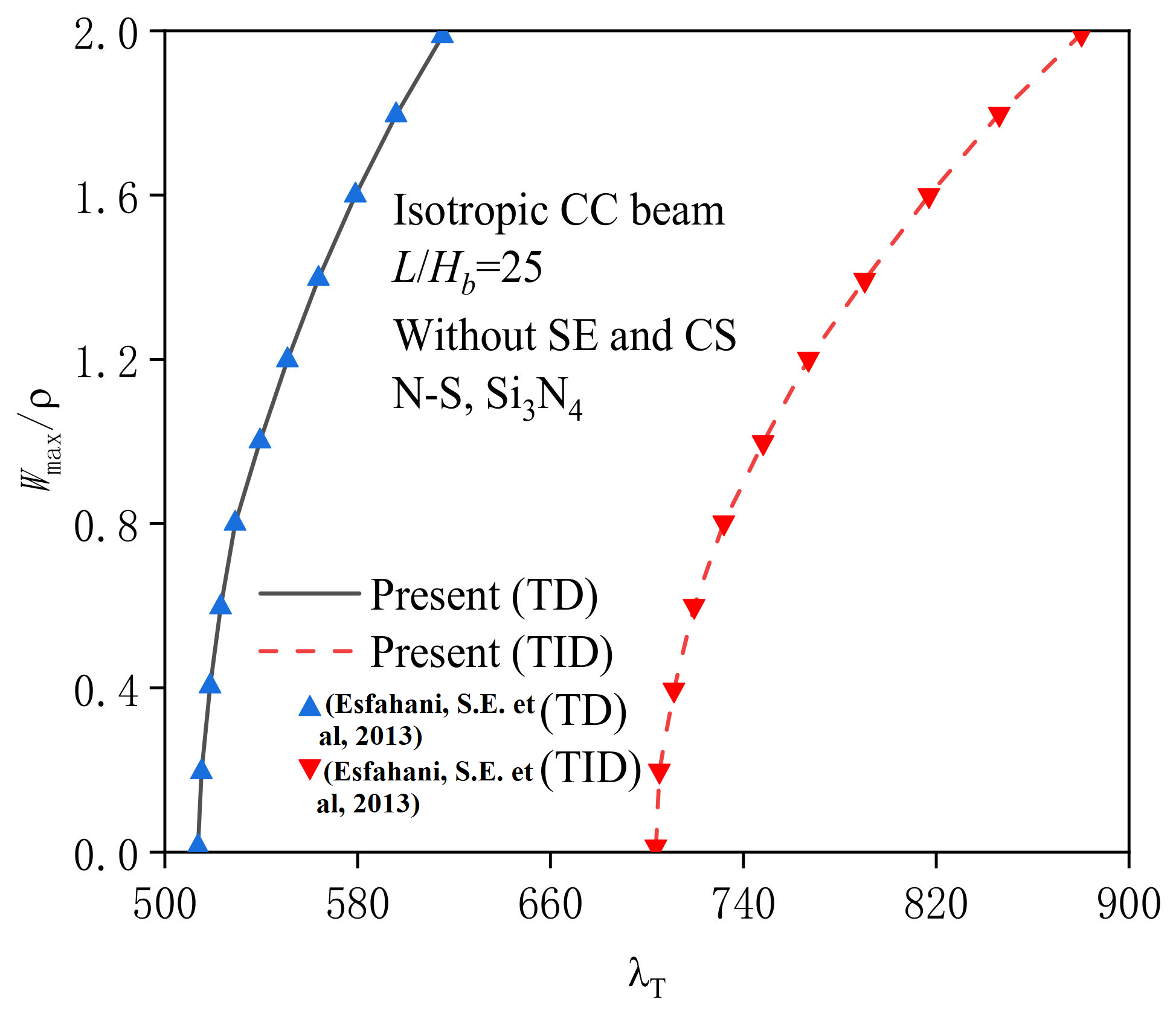
4.1. Verification Study

The current model can degenerate into the size-independent one by setting μ S ( 1 ) = μ S ( 2 ) = 0 N/m and l = 0 nm. Here, the isotropic macrobeam made of metal/ceramic phases is selected, and effective material properties can be found in Ref. [54]. Table 1 and Table 2 compare the results of the critical buckling temperature quantity Δ T c r α 0 L / H b 2 for a macrobeam under various boundary conditions with results in previous works. Table 1 shows that the present results are larger than the available ones in [54]. The differences between the two are attributed to the fact that the existing theoretical model is based on the Reddy’s higher-order shear deformation theory, while our model is based on the Euler–Bernoulli beam theory. The introduction of shear deformation effect will weaken the structural bending rigidity. Moreover, the bending moment is assumed as a function of coordinates in Ref. [54], which is actually unreasonable. In Table 2, one can observe that the present results and the reported ones in Ref. [55] have a good consistency. To provide a consistent comparison with previous works, Figure 3 presents the thermal postbuckling equilibrium path of a CC macrobeam with TD and TID cases, where ρ = A Z 2 d A / A denotes the radius of gyration. As expected, the results in this paper are consistent with those in the literature.

4.2. Parametric Studies

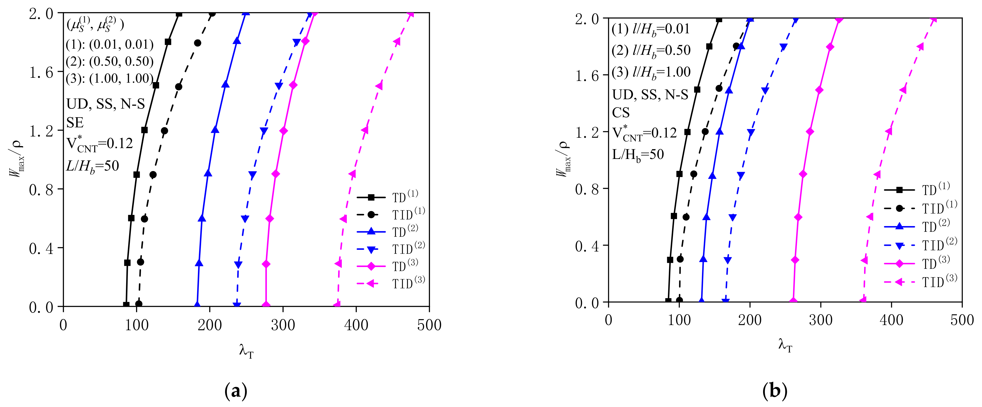
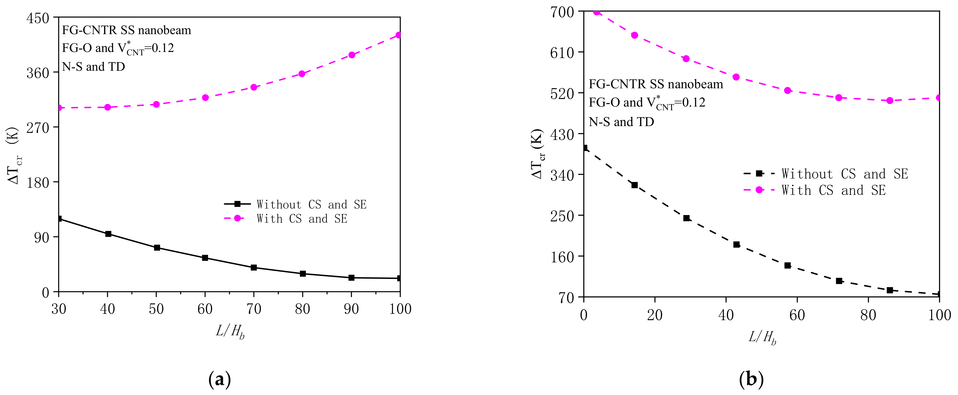
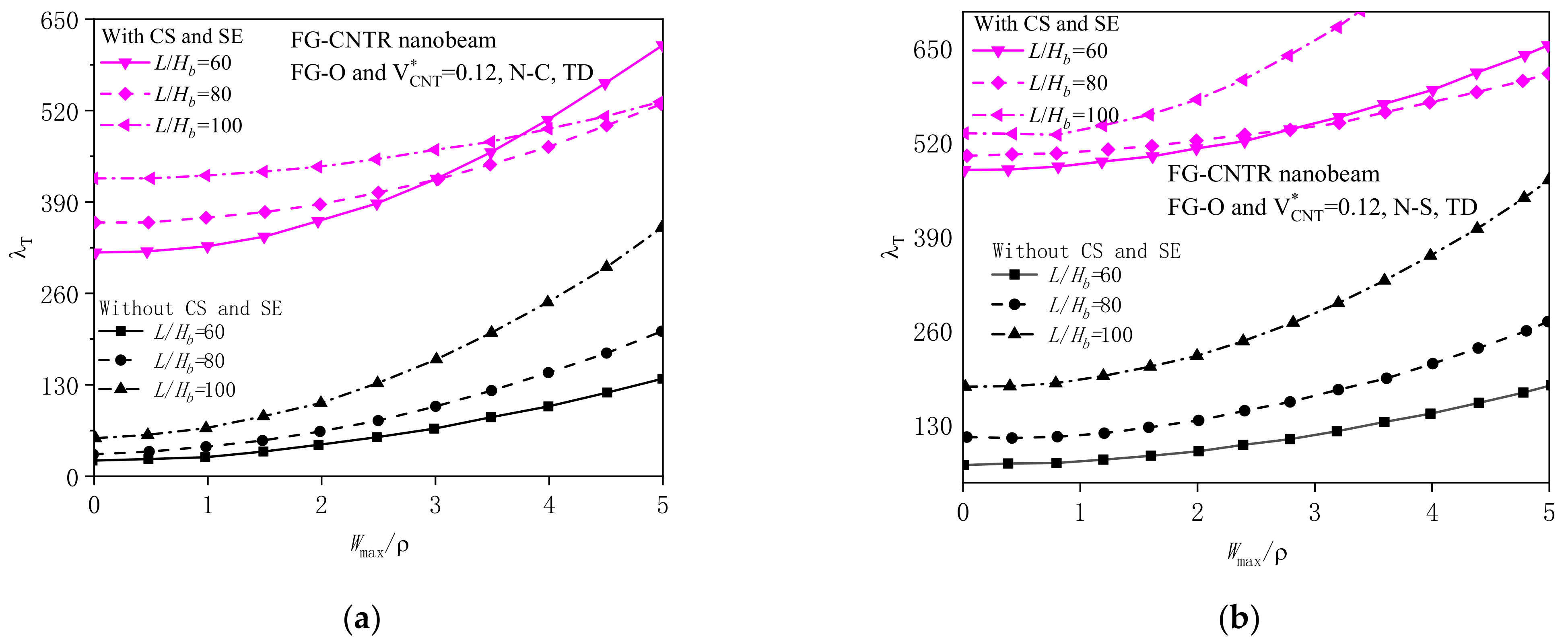
4.2.1. Effects of Surface Energy and Couple Stress

In this section, parametric studies are presented to the show surface energy and couple stress effects on the postbuckling behaviors of FG-CNTR nanobeams under different boundary conditions (BC). For simplicity, the following analysis uses the abbreviations “SE” and “CS”, respectively, to refer to the case of only including surface energy ( l = 0 ) and the case of only including couple stress ( μ S ( 1 ) = μ S ( 2 ) = 0 ). Here, H b = 20 nm, b = 40 nm, and V C N T * = 0.12 .
Table 3 and Table 4 tabulate the critical thermal buckling temperature Δ T c r for six groups of SE and CS parameters, respectively. Here, only the UD nanobeam with SS ends is selected. These results confirm that both SE and CS have pronounced effects on the critical buckling temperature Δ T c r . For smaller SE and CS parameters, 0.01 μ S ( 1 ) and 0.01 μ S ( 2 ) (see Table 3) or l / H b = 0.01 (see Table 4), the buckling load approaches the classical one (i.e., μ S ( 1 ) = μ S ( 2 ) = 0 and l / H b = 0 ). Generally, the stronger the size effects, the larger the buckling temperature Δ T c r . Furthermore, the buckling temperature Δ T c r of a nanobeam with a TID case is much higher than the nanobeam with TD case; hence, the TID condition may be overestimated with regards to the critical thermal buckling responses.
Figure 4 shows the SE and CE effects (i.e., μ S ( 1 ) , μ S ( 2 ) , and l / H b ) on the postbuckling behaviors of nanobeams. As the SE and CS parameters tend to zero, e.g., 0.01 μ S ( 1 ) , 0.01 μ S ( 2 ) , and l / H b = 0.01 , the postbuckling response approaches the classical one. By increasing the SE and CS parameters, the critical buckling temperature load and the stability of the UD nanobeam increase, which implies the larger values of SE and CE parameters generate larger additional bending rigidity. According to Table 3 and Table 4 and Figure 4, it can be concluded that an increase in μ S ( i )   i = 1 , 2 or l / H b postpones the branching point of the nanobeam. Additionally, for the uniform temperature field, the thermal postbuckling load–deflection curve of UD nanobeams is of the bifurcation buckling type. Meanwhile, the difference between the TID and TD cases becomes higher at the larger SE and CS parameters. The reason is that increasing the SE and CS parameters would lead to an increase of structural bending rigidity, especially for the TID case.
Figure 5 exhibits the SE and CE effects on the critical buckling load of a UD nanobeam with l / H b = 50 . Clearly, the SE and CS make positive contributions to increasing the buckling load Δ T c r , which means small-scale effects may exert a considerable rigidity and make nanobeams harder to deform. These contributions are more prominent, especially when the l / H b is large. However, the TD case exhibits a negative impact on the buckling temperature when compared with those of the TID case, and this phenomenon is more remarkable when considering the SE effect.
As predicted from Figure 6 for the SE, CS, and SE-CS analyses, the postbuckling load–deflection curves are sensitive for the CS effects. Obviously, the biggest effect of the scale parameter is associated with the SE-CS response. Moreover, an interesting result observed from Figure 5 and Figure 6 is that the SE is more dominant than CS for the present nanostructures. Thus, although the surface of a nanobeam system is modeled as an infinitely thin thickness (zero-thickness) layer, the characteristics of this layer could also significantly influence the buckling responses.

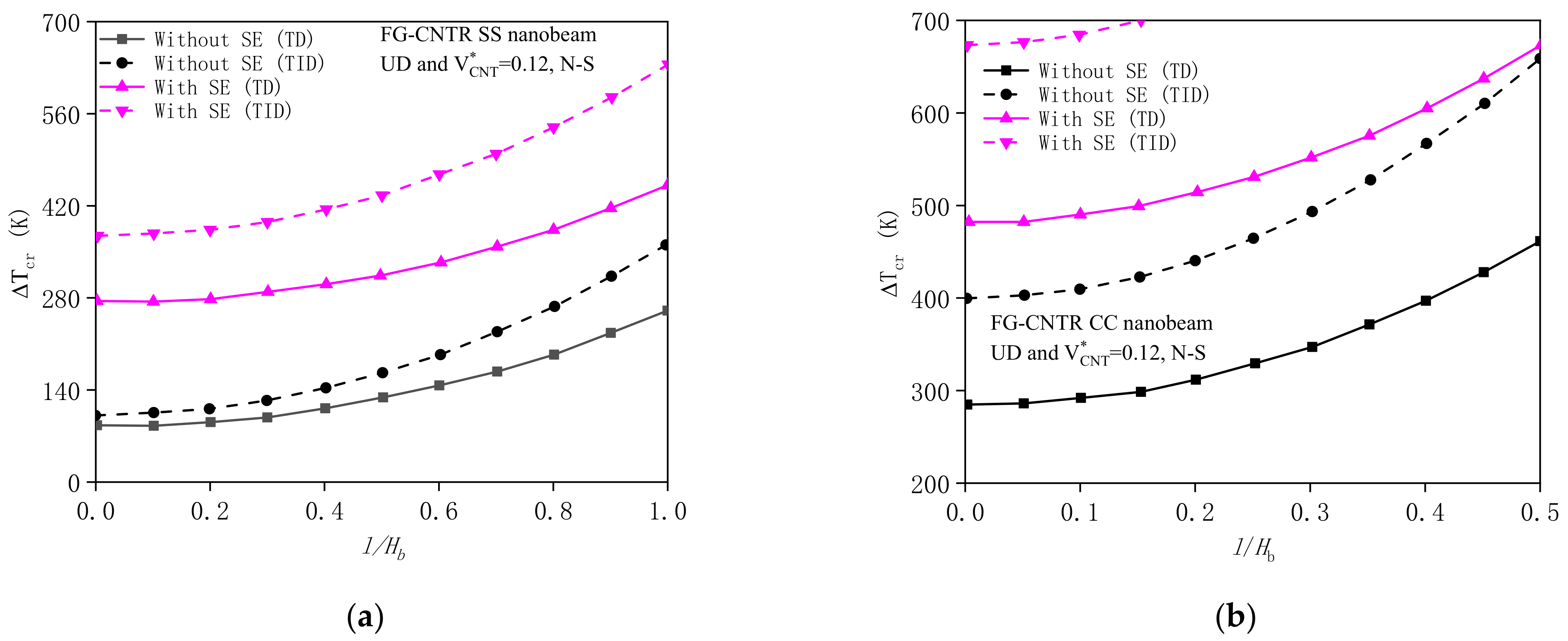
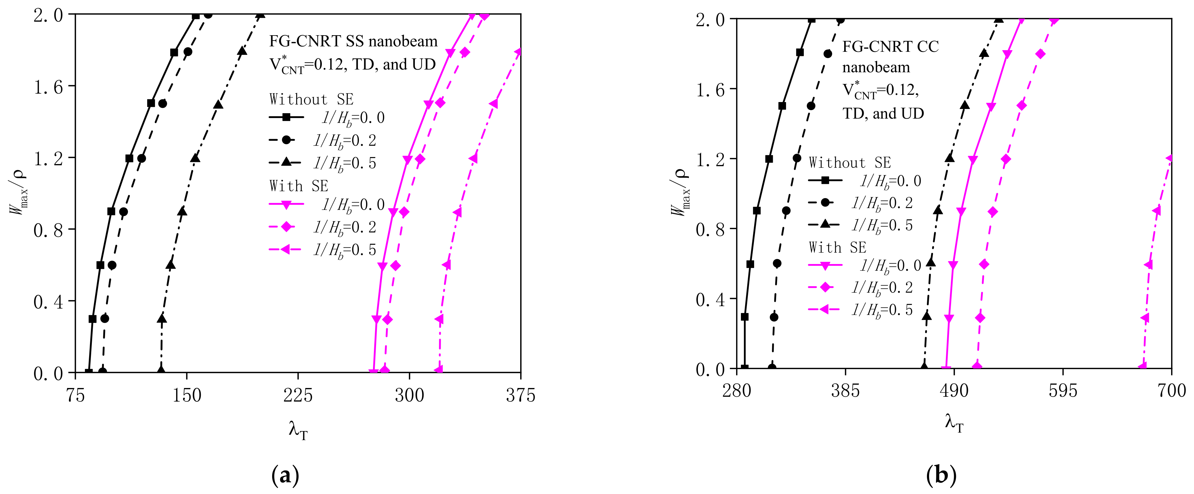
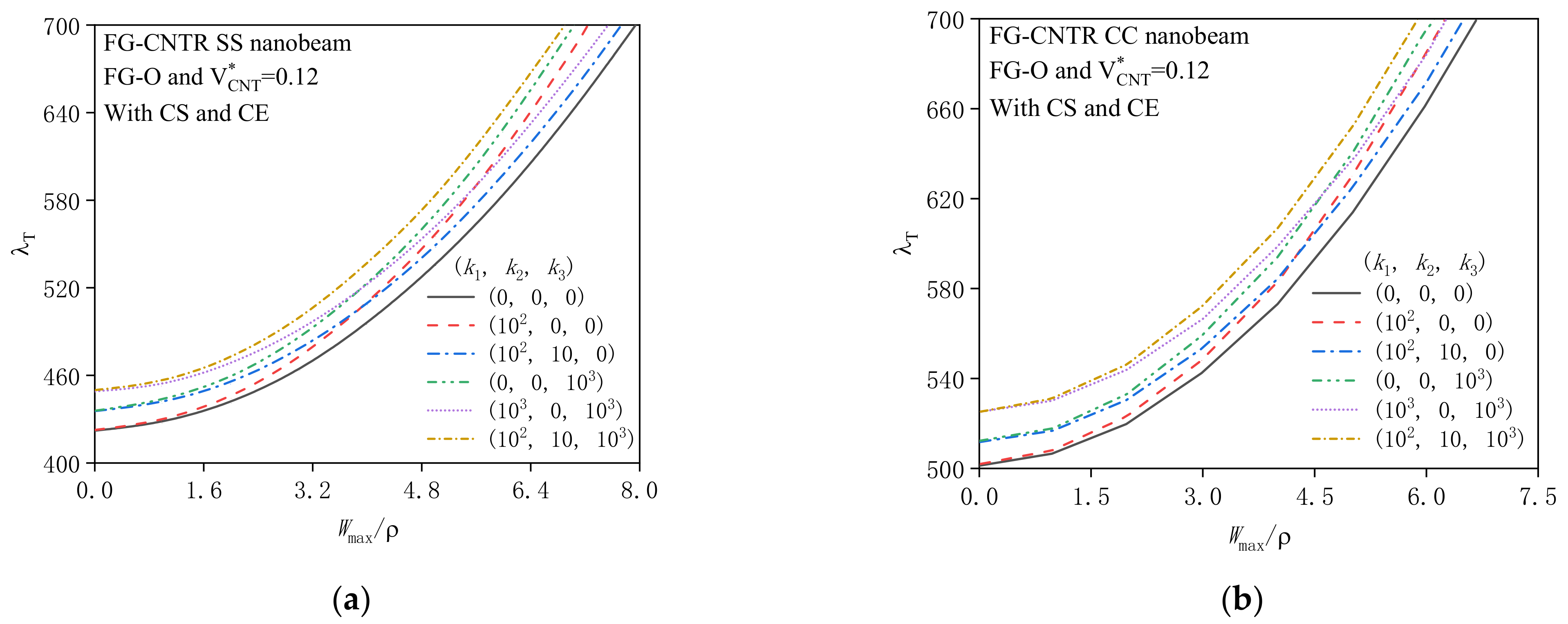
4.2.2. Effects of Geometrical Property and Substrate Stiffness

In this section, the impacts of the aspect ratio ( l / H b ) and substrate stiffness constants ( k 1 , k 2 , and k 3 ) on the buckling analysis of FG-O nanobeams with V C N T * = 0.12 are discussed in detail. The geometrical properties adopted are: L = 1000 nm, b = 40 nm. The combined effects of SE and CS and effective TD material properties are also involved in the present size-dependent model, and the same below.
In Figure 7, the effects of aspect ratio l / H b on the buckling load Δ T c r are depicted. It is again observed that the maximum buckling temperature is associated with SE-CS analysis, while the minimum is associated with classical elasticity analysis. Additionally, for classical results, the buckling temperature decrease with increasing the ratio l / H b , which is due to the reduced total stiffness of the structure. However, as predicted from Figure 7a for the size-dependent nanobeam with SS ends, the critical buckling temperature enhances as the ratio l / H b increases, and as the ratio l / H b increases, the SE and CE effects gradually become significant.
Figure 8 shows that, in the beginning, the paths of the load–deflection stage predicated by the size-dependent model are higher than that of the corresponding classical model, especially for large aspect ratios. Moreover, in the deep postbuckling region, the load–deflection curves calculated by both models have similar distribution patterns. For instance, the postbuckling response is the greatest for the nanobeam at l / H b = 60 , followed by l / H b = 80 and l / H b = 100 third.
The postbuckling load–deflection curves with different substrate models are plotted in Figure 9. An FG-O curved nanobeam with l / H b = 100 is selected. To capture the reactions acting on nanobeams from the foundation, the concepts of three substrate models are introduced. The elastic substrates are characterized by k 1 , k 2 , k 3 = 100 , 0 , 0 for the Winkler substrate (W-S), k 1 , k 2 , k 3 = 100 , 10 , 0 for the Pasternak substrate (P-S), and k 1 , k 2 , k 3 = 100 , 10 , 1000 for a tri-parameter nonlinear substrate (T-S). Evidently, k 1 , k 2 , k 3 = 0 , 0 , 0 stands for no substrate (N-S). It is noticed that the nonlinear stiffness (e.g., k 3 = 1000 ) has no contribution on the buckling load Δ T c r ; however, its effect is a dominant factor for the postbuckling analysis. Generally, the increasing substrate stiffness constants k 1 , k 2 , and k 3 lead to a lower deflection in the postbuckling behavior due to enhancement of the reaction force of the nanobeam from substrates.

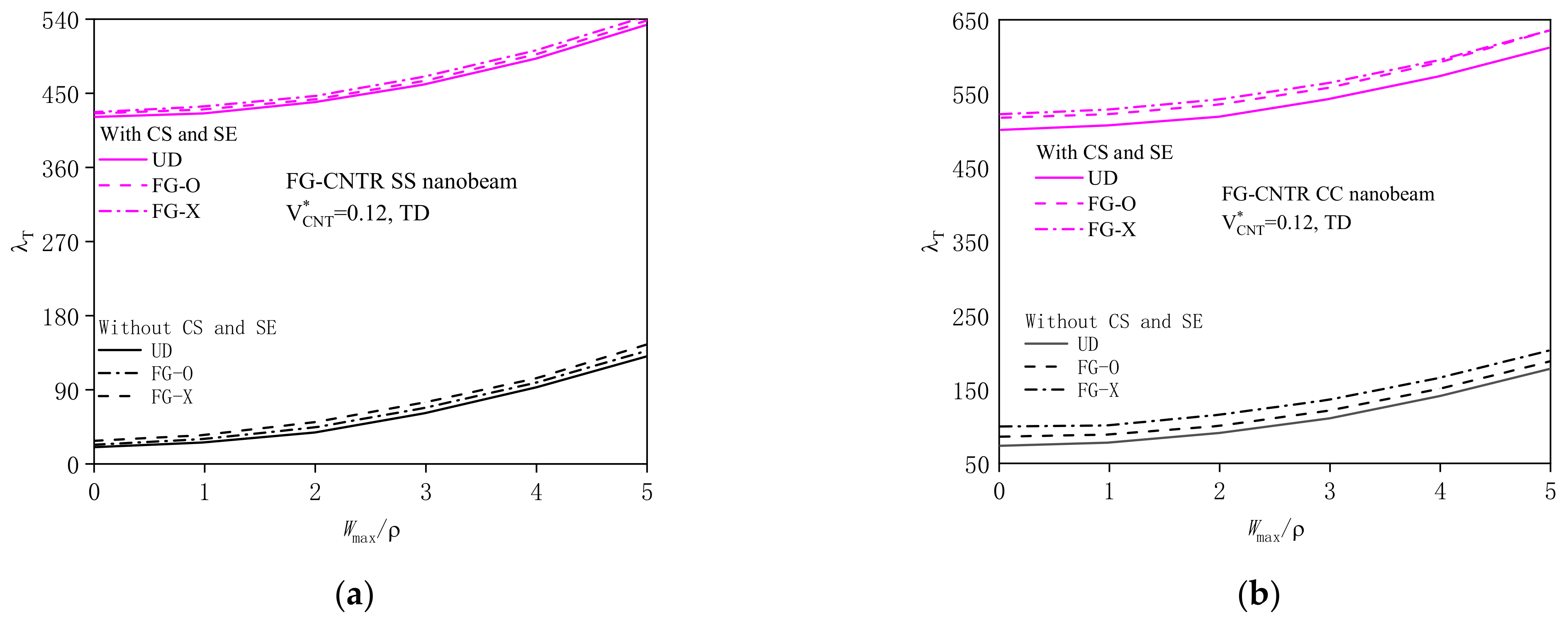
4.2.3. Effect of Material Properties

Figure 10 shows the distributions of CNT reinforcements on the postbuckling behavior of FG nanobeams with V C N T * = 0.12 and l / H b = 100 . Three types of CNTs, i.e., UD, FG-O, and FG-X, are studied. It is proved that neglecting the small-scale effects may cause the errors for researching the postbuckling response of the FG nanobeam with different patterns of CNTs. Furthermore, results in Figure 10 also confirm that the structure with the FG-X pattern has the biggest postbuckling temperature, followed by the UD and FG-O types. Briefly, the FG-X nanobeam is the optimum pattern in this case.
Figure 11 shows the postbuckling behavior of UD and FG-X nanobeams with different CNT volume fractions. Obviously, the CNT volume percent V C N T * = 0.12 ,   0.17 ,   and   0.28 plays a key role in the buckling and postbuckling responses. The FG-X nanobeam with V C N T * = 0.12 has the highest critical buckling temperature and thermal postbuckling strength. Furthermore, from Figure 10 and Figure 11, it can be drawn that the buckling load as well as postbuckling strength of FG-X nanobeam are higher than those of the UD nanobeam, while they slightly affect the responses when considering scale effects or decreasing V C N T * .

5. Concluding Remarks

According to Chen-Yao’s SET and Yang’s symmetrical CST, the thermal buckling and postbuckling analyses of FG-CNTR nanobeams under uniform temperature rise were con-ducted. All the thermomechanical material characteristics for CNT-based nanobeams are position- and temperature-dependent. The impacts of different parameters, particularly two types of size effects, on thermal buckling and post buckling were investigated via a two-step perturbation method. Major conclusions can be summarized as follows: (1) As the two types of size effects increase, the thermal buckling and postbuckling responses of nanobeams decrease. This indicates that the SE and CS effects can enhance the structural bending rigidity. Moreover, there is a reverse competition between the SE and CS effects on the thermal buckling responses of nanobeams. (2) As the slenderness ratio increases, the thermal buckling responses of the nanobeam increase. The larger the slenderness ratio is, the more significant the two types of size effects, which are quite different from the classical ones. The CNT distribution patterns and the volume percent play a key role in thermal buckling responses. (3) The TID’s thermal buckling load–deflection curves of nanobeams are much higher than the TD’s, especially for larger surface energy effects. The reason is that the increase of temperature will cause the material to soften. Therefore, further efforts should be devoted to developing nonlinear, finite element models of size-dependent theories, especially the symmetrical CST and SET-based models for practical applications.

Author Contributions

Conceptualization, L.K. and C.L.; methodology, B.Z.; experiment and data analysis, B.Z. and L.K.; writing—original draft preparation, B.Z.; writing—review and editing, L.K. and C.L.; funding acquisition, B.Z. and C.L. All authors have read and agreed to the published version of the manuscript.

Funding

This work was financially supported by the National Natural Science Foundation of China (No. 11602204), the Fundamental Research Funds for the Central Universities of China (No. 2682022ZTPY081), and the Open project of Applied Mechanics and Structure Safety Key Laboratory of Sichuan Province (No. SZDKF-202102).

Data Availability Statement

All data, models, or codes generated or used during the study are available from the corresponding author by request.

Conflicts of Interest

The authors declare no conflict of interest.

References

  1. Reddy, J.N. Nonlocal nonlinear formulations for bending of classical and shear deformation theories of beams and plates. Int. J. Eng. Sci. 2010, 48, 1507–1518. [Google Scholar] [CrossRef]
  2. Reddy, J.N. Microstructure-dependent couple stress theories of functionally graded beams. J. Mech. Phys. Solids 2011, 59, 2382–2399. [Google Scholar] [CrossRef]
  3. Ong, O.Z.S.; Ghayesh, M.H.; Losic, D.; Amabili, M. Coupled dynamics of double beams reinforced with bidirectional functionally graded carbon nanotubes. Eng. Anal. Bound. Elem. 2022, 143, 263–282. [Google Scholar] [CrossRef]
  4. Lam, D.C.; Yang, F.; Chong, A.; Wang, J.; Tong, P. Experiments and theory in strain gradient elasticity. J. Mech. Phys. Solids 2003, 51, 1477–1508. [Google Scholar] [CrossRef]
  5. Xie, Y.; Lei, J.; Guo, S.; Han, S.; Ruan, J.; He, Y. Size-dependent vibration of multi-scale sandwich micro-beams: An experimental study and theoretical analysis. Thin Wall. Struct. 2022, 175, 109115. [Google Scholar] [CrossRef]
  6. Li, Z.; He, Y.; Lei, J.; Han, S.; Guo, S.; Liu, D. Experimental investigation on size-dependent higher-mode vibration of cantilever microbeams. Microsyst. Technol. 2019, 25, 3005–3015. [Google Scholar]
  7. Li, Z.; He, Y.; Lei, J.; Guo, S.; Liu, D.; Wang, L. A standard experimental method for determining the material length scale based on modified couple stress theory. Int. J. Mech. Sci. 2018, 141, 198–205. [Google Scholar] [CrossRef]
  8. Lei, J.; He, Y.; Guo, S.; Li, Z.; Liu, D. Size-dependent vibration of nickel cantilever microbeams: Experiment and gradient elasticity. AIP Adv. 2016, 6, 105202. [Google Scholar] [CrossRef] [Green Version]
  9. Fleck, N.; Muller, G.; Ashby, M.; Hutchinson, J. Strain gradient plasticity: Theory and experiment. Acta Metall. Mater. 1994, 42, 475–487. [Google Scholar] [CrossRef]
  10. Liu, D.; He, Y.; Tang, X.; Ding, H.; Hu, P.; Cao, P. Size effects in the torsion of microscale copper wires: Experiment and analysis. Scripta Mater. 2012, 66, 406–409. [Google Scholar] [CrossRef]
  11. Polyzos, D.; Huber, G.; Mylonakis, G.; Triantafyllidis, T.; Papargyri-Beskou, S.; Beskos, D. Torsional vibrations of a column of fine-grained material: A gradient elastic approach. J. Mech. Phys. Solids 2015, 76, 338–358. [Google Scholar] [CrossRef]
  12. Guo, S.; He, Y.; Liu, D.; Lei, J.; Li, Z.; Ding, H. Torsional stress relaxation behavior of microscale copper wire. Mater. Sci. Eng. A 2017, 698, 277–281. [Google Scholar] [CrossRef]
  13. Eringen, A.C. Nonlocal polar elastic continua. Int. J. Eng. Sci. 1972, 10, 1–16. [Google Scholar] [CrossRef]
  14. Eringen, A.C. On differential equations of nonlocal elasticity and solutions of screw dislocation and surface waves. J. Appl. Phys. 1983, 54, 4703–4710. [Google Scholar] [CrossRef]
  15. Mindlin, R.; Tiersten, H. Effects of couple-stresses in linear elasticity. Arch. Ration. Mech. An. 1962, 11, 415–448. [Google Scholar] [CrossRef]
  16. Toupin, R.A. Theories of elasticity with couple-stress. Arch. Ration. Mech. An. 1964, 17, 85–112. [Google Scholar] [CrossRef]
  17. Yang, F.; Chong, A.C.M.; Lam, D.C.C.; Tong, P. Couple stress based strain gradient theory for elasticity. Int. J. Solids Struct. 2002, 39, 2731–2743. [Google Scholar] [CrossRef]
  18. Hadjesfandiari, A.R.; Dargush, G.F. Couple stress theory for solids. Int. J. Solids Struct. 2011, 48, 2496–2510. [Google Scholar] [CrossRef] [Green Version]
  19. Mindlin, R.D. Second gradient of strain and surface-tension in linear elasticity. Int. J. Solids Struct. 1965, 1, 417–438. [Google Scholar] [CrossRef]
  20. Mindlin, R.; Eshel, N. On first strain-gradient theories in linear elasticity. Int. J. Solids Struct. 1968, 4, 109–124. [Google Scholar] [CrossRef]
  21. Cordero, N.M.; Forest, S.; Busso, E.P. Second strain gradient elasticity of nano-objects. J. Mech. Phys. Solids 2016, 97, 92–124. [Google Scholar] [CrossRef]
  22. Zhou, S.; Li, A.; Wang, B. A reformulation of constitutive relations in the strain gradient elasticity theory for isotropic materials. Int. J. Solids Struct. 2016, 80, 28–37. [Google Scholar] [CrossRef]
  23. Fu, G.; Zhou, S.; Qi, L. On the strain gradient elasticity theory for isotropic materials. Int. J. Eng. Sci. 2020, 154, 103348. [Google Scholar] [CrossRef]
  24. Gurtin, M.E.; Murdoch, A.I. A continuum theory of elastic material surfaces. Arch. Ration. Mech. An. 1975, 57, 291–323. [Google Scholar] [CrossRef]
  25. Ma, X.; Chen, W. 24-DOF quadrilateral hybrid stress element for couple stress theory. Comput. Mech. 2014, 53, 159–172. [Google Scholar] [CrossRef]
  26. Gurtin, M.E.; Murdoch, A.I. Surface stress in solids. Int. J. Solids Struct. 1978, 14, 431–440. [Google Scholar] [CrossRef]
  27. Thai, H.T.; Vo, T.P.; Nguyen, T.K.; Kim, S.E. A review of continuum mechanics models for size-dependent analysis of beams and plates. Compos. Struct. 2017, 177, 196–219. [Google Scholar] [CrossRef]
  28. Roudbari, M.A.; Jorshari, T.D.; Lü, C.; Ansari, R.; Kouzani, A.Z.; Amabili, M. A review of size-dependent continuum mechanics models for micro-and nano-structures. Thin Wall. Struct. 2022, 170, 108562. [Google Scholar] [CrossRef]
  29. Gao, X.L.; Mahmoud, F.F. A new Bernoulli–Euler beam model incorporating microstructure and surface energy effects. Z. Angew. Math. Phys. 2014, 65, 393–404. [Google Scholar] [CrossRef]
  30. Gao, X.L. A new Timoshenko beam model incorporating microstructure and surface energy effects. Acta. Mech. 2015, 226, 457–474. [Google Scholar] [CrossRef]
  31. Gao, X.L.; Zhang, G. A microstructure-and surface energy-dependent third-order shear deformation beam model. Z. Angew. Math. Phys. 2015, 66, 1871–1894. [Google Scholar] [CrossRef]
  32. Gao, X.L.; Zhang, G. A non-classical Kirchhoff plate model incorporating microstructure, surface energy and foundation effects. Contin. Mech. Therm. 2016, 28, 195–213. [Google Scholar] [CrossRef]
  33. Gao, X.L.; Zhang, G. A non-classical Mindlin plate model incorporating microstructure, surface energy and foundation effects. Proc. R. Soc. A Math. Phys. Eng. Sci. 2016, 472, 20160275. [Google Scholar] [CrossRef] [PubMed] [Green Version]
  34. Yin, S.; Deng, Y.; Zhang, G.; Yu, T.; Gu, S. A new isogeometric Timoshenko beam model incorporating microstructures and surface energy effects. Math. Mech. Solids 2020, 25, 2005–2022. [Google Scholar] [CrossRef]
  35. Zhang, B.; Shen, H.; Liu, J.; Wang, Y.; Zhang, Y. Deep postbuckling and nonlinear bending behaviors of nanobeams with nonlocal and strain gradient effects. Appl. Math. Mech. 2019, 40, 515–548. [Google Scholar] [CrossRef]
  36. Allahkarami, F.; Nikkhah-Bahrami, M. The effects of agglomerated CNTs as reinforcement on the size-dependent vibration of embedded curved microbeams based on modified couple stress theory. Mech. Adv. Mater. Struct. 2017, 25, 995–1008. [Google Scholar] [CrossRef]
  37. Thanh, C.L.; Phung-Van, P.; Thai, C.H.; Nguyen-Xuan, H.; Wahab, M.A. Isogeometric analysis of functionally graded carbon nanotube reinforced composite nanoplates using modified couple stress theory. Compos. Struct. 2018, 184, 633–649. [Google Scholar] [CrossRef]
  38. Zhang, B.; Li, H.; Liu, J.; Shen, H.; Zhang, X. Surface energy-enriched gradient elastic Kirchhoff plate model and a novel weak-form solution scheme. Eur. J. Mech. A-Solids 2021, 85, 104118. [Google Scholar] [CrossRef]
  39. Zhang, B.; Li, H.; Kong, L.; Shen, H.; Zhang, X. Coupling effects of surface energy, strain gradient, and inertia gradient on the vibration behavior of small-scale beams. Int. J. Mech. Sci. 2020, 184, 105834. [Google Scholar] [CrossRef]
  40. Eftekhari, S.A.; Toghraie, D. Vibration and dynamic analysis of a cantilever sandwich microbeam integrated with piezoelectric layers based on strain gradient theory and surface effects. Appl. Math. Comput. 2022, 419, 126867. [Google Scholar]
  41. Dangi, C.; Lal, R.; Sukavanam, N. Effect of surface stresses on the dynamic behavior of bi-directional functionally graded nonlocal strain gradient nanobeams via generalized differential quadrature rule. Eur. J. Mech. A-Solids 2021, 90, 104376. [Google Scholar] [CrossRef]
  42. Shanab, R.; Attia, M.; Mohamed, S. Nonlinear analysis of functionally graded nanoscale beams incorporating the surface energy and microstructure effects. Int. J. Mech. Sci. 2017, 131, 908–923. [Google Scholar] [CrossRef]
  43. Shaat, M.; Mahmoud, F.; Gao, X.L.; Faheem, A.F. Size-dependent bending analysis of Kirchhoff nano-plates based on a modified couple-stress theory including surface effects. Int. J. Mech. Sci. 2014, 79, 31–37. [Google Scholar] [CrossRef]
  44. Lu, L.; Guo, X.; Zhao, J. A unified size-dependent plate model based on nonlocal strain gradient theory including surface effects. Appl. Math. Model. 2019, 68, 583–602. [Google Scholar] [CrossRef]
  45. Duong, V.Q.; Tran, N.D.; Luat, D.T.; Thom, D.V. Static analysis and boundary effect of FG-CNTRC cylindrical shells with various boundary conditions using quasi-3D shear and normal deformations theory. Structures 2022, 44, 828–850. [Google Scholar] [CrossRef]
  46. Duc, D.H.; Thom, D.V.; Cong, P.H.; Minh, P.V.; Nguyen, N.X. Vibration and static buckling behavior of variable thickness flexoelectric nanoplates. Mech. Based. Des. Struc. 2022, 1–29. [Google Scholar] [CrossRef]
  47. Van Do, T.; Doan, D.H.; Tho, N.C.; Duc, N.D. Thermal buckling analysis of cracked functionally graded plates. Int. J. Struct. Stab. Dy. 2022, 22, 2250089. [Google Scholar] [CrossRef]
  48. Van Do, T.; Doan, D.H.; Duc, N.D.; Bui, T.Q. Phase-field thermal buckling analysis for cracked functionally graded composite plates considering neutral surface. Compos. Struct. 2017, 182, 542–548. [Google Scholar] [CrossRef]
  49. Shen, H.S.; Xiang, Y. Nonlinear analysis of nanotube-reinforced composite beams resting on elastic foundations in thermal environments. Eng. Struct. 2013, 56, 698–708. [Google Scholar] [CrossRef]
  50. Shen, H.S. Nonlinear bending of functionally graded carbon nanotube-reinforced composite plates in thermal environments. Compos. Struct. 2009, 91, 9–19. [Google Scholar] [CrossRef]
  51. Shen, H.S. A Two-Step Perturbation Method in Nonlinear Analysis of Beams, Plates and Shells; Higher Education Press: Beijing, China, 2013. [Google Scholar]
  52. Shen, H.S.; Zhang, C.L. Nonlocal beam model for nonlinear analysis of carbon nanotubes on elastomeric substrates. Comp. Mater. Sci. 2011, 50, 1022–1029. [Google Scholar] [CrossRef]
  53. Sahmani, S.; Bahrami, M.; Aghdam, M.M. Surface stress effects on the postbuckling behavior of geometrically imperfect cylindrical nanoshells subjected to combined axial and radial compressions. Int. J. Mech. Sci. 2015, 100, 1–22. [Google Scholar] [CrossRef]
  54. Shen, H.S.; Wang, Z.X. Nonlinear analysis of shear deformable FGM beams resting on elastic foundations in thermal environments. Int. J. Mech. Sci. 2014, 81, 195–206. [Google Scholar] [CrossRef]
  55. Esfahani, S.E.; Kiani, Y.; Eslami, M.R. Non-linear thermal stability analysis of temperature dependent FGM beams supported on non-linear hardening elastic foundations. Int. J. Mech. Sci. 2013, 69, 10–20. [Google Scholar] [CrossRef]
Figure 1. An FG-CNTR nanobeam resting on a nonlinear Winkler–Pasternak elastic foundation.
Symmetry 14 02228 g001
Figure 2. Distributing patterns of CNTs: (a) UD; (b) FG-X; (c) FG-O.
Symmetry 14 02228 g002
Figure 3. Comparisons of the postbuckling equilibrium path for the metal/ceramic macrobeam: CC ends [55].
Symmetry 14 02228 g003
Figure 4. Thermal postbuckling response of UD nanobeams under different scale parameters: (a) SE ( l = 0 ); (b) CS ( μ S ( 1 ) = μ S ( 2 ) = 0 ).
Symmetry 14 02228 g004
Figure 5. Combined effects of SE and CS on the critical buckling temperature Δ T c r : (a) SS ends; (b) CC ends.
Symmetry 14 02228 g005
Figure 6. Combined effects of surface energy and CS on thermal postbuckling response: (a) SS ends; (b) CC ends.
Symmetry 14 02228 g006
Figure 7. Variation of critical buckling temperature with respect to L / H b : (a) SS ends; (b) CC ends.
Symmetry 14 02228 g007
Figure 8. Thermal postbuckling responses with respect to l / H b : (a) SS ends; (b) CC ends.
Symmetry 14 02228 g008
Figure 9. Effects of various elastic media on thermal postbuckling response: (a) SS ends; (b) CC ends.
Symmetry 14 02228 g009
Figure 10. Effects of CNT patterns on thermal postbuckling response: (a) SS ends; (b) CC ends.
Symmetry 14 02228 g010
Figure 11. Effects of CNT volume percent on thermal postbuckling response: (a) SS ends; (b) CC ends.
Symmetry 14 02228 g011
Table 1. Critical buckling temperature Δ T c r α 0 L / H b 2 of SS beams at L / H b = 20 .
MaterialsTIDTD
Shen and Wang [54]PresentShen and Wang [54]Present
SUS3040.6190.6610.5820.595
Si3N41.3501.3551.1851.189
ZrO20.5180.5440.4160.416
Al2O31.3791.4061.3261.342
( α 0 = 12.33 × 10 6 1 / K ).
Table 2. Critical buckling temperature Δ T c r α 0 L / H b 2 of CC beams at L / H b = 25 .
MaterialsTIDTD
Esfahani et al. [55]PresentEsfahani et al. [55]Present
Si3N45.3385.4213.9163.916
n = 2.0 3.2633.3152.6592.659
n = 5.0 3.0393.0892.5152.515
n = 10.0 2.8982.9462.4162.416
SUS3042.6042.6442.1962.196
Table 3. Surface effect on the critical thermal buckling temperature Δ T c r .
BC μ S ( 1 ) , μ S ( 2 )
(0.0,0.0)(0.01,0.01)(0.3,0.3)(0.4,0.4)(0.5,0.5)(1.0,1.0)
SSTID99.666102.403181.784209.157318.649373.396
TD84.67386.757144.498163.580238.170275.293
CCTID398.665401.411481.068508.536536.004673.345
TD286.336288.179342.325361.386380.695481.673
Table 4. CS on critical thermal buckling temperature Δ T c r .
BC l / H b
0.00.10.20.30.40.5
SSTID99.66699.692110.095123.131141.383164.848
TD84.67384.69292.488102.092115.266131.816
CCTID398.665398.768440.381492.527565.531659.393
TD286.336286.403313.451347.616396.229460.486
Publisher’s Note: MDPI stays neutral with regard to jurisdictional claims in published maps and institutional affiliations.

