1. Introduction
WSNs (Wireless Sensor Networks) are a network system composed of one or several wireless data collectors and numerous sensors. The communication method between components uses wireless communication to communicate. A wireless sensor network may consist of tens to hundreds or even thousands of sensor nodes. These nodes are scattered in large areas and are responsible for collecting data on the surrounding environment. The Base Station or Gateway Node in the network is responsible for collecting the data of the sensor nodes. However, due to the hardware limitations of these sensor nodes, the sensor nodes have only low computing power, low storage capacity, and low communication bandwidth. Therefore, they are suitable for a lightweight identity authentication mechanism.
The Internet of Things architecture is generally defined as three layers: perception layer, network layer, and application layer. The perception layer is the lowest level architecture of the Internet of Things, collecting and processing basic data. The network layer is responsible for processing the data of the perception layer and transmitting it to the application layer quickly and safely. The application layer is responsible for providing services for specific purposes, collecting and judging sensor data, and developing different applications. Mehta et al. explained the attack on the three-tier architecture of the Internet of Things [
1], for example, DoS (Denial-of-Service) attacks, data theft attacks, etc. The identification of users and devices is an effective way to prevent such attacks. Many papers have proposed similar methods. Alharbi et al. used NFC (Near-field communication) to authenticate users [
2], and Gope et al. used PUF technology to provide an immutable identity [
3].
Recently, due to the rise of blockchain technology, blockchain has become one of the solutions for the Internet of Things [
4]. Novo et al. used Ethereum technology to set up a private chain and build a system that is easy to access control [
5]. Huh et al. used the Ethereum smart contract to manage the RSA public key, and the private key stored by a separate device, which can effectively control the identity of the IoT device [
6]. However, the application of blockchain in the Internet of Things still has its limitations, for example, throughput, scalability, and handling fees, etc. Therefore, this paper uses IOTA technology based on Directed Acyclic Graph (DAG) to establish a security architecture. This technology uses a lightweight PoW (Proof-of-Work) consensus algorithm. The feature of this mechanism is that there is no role of miners, but everyone is involved in bookkeeping. Uploading a transaction must first verify the two transactions in the transaction pool, so no commission is required. In terms of speed, it is much faster than the Ethereum public chain. Due to the characteristics of its public ledger, it also has a higher credibility than Hyperledger’s consortium chain [
7,
8,
9] and other papers mentioned the evolution of consensus mechanisms, from PoW to PoS, and then to DAG-based consensus mechanisms. DAG is more suitable for IoT applications than traditional blockchains. IOTA is the most suitable solution for the Internet of Things because it provides free data storage and resists issues such as double payment and quantum attacks.
Although IOTA has been used in many IoT applications, most of their limitations are that sensor nodes must be directly connected to IOTA nodes. However, many sensors are on the internal network, and some do not even have Internet connectivity, and cannot implement IOTA transaction signatures, for example, WSNs. Therefore, [
10] divides the architecture of IOTA Tangle into three types, as shown in
Figure 1.
The three ways to upload tangle are as follows:
After the embedded system reads the data, the data read is sent to the computer. After the computer collects the data, the data collected is forwarded to the remote server. The remote server packages the data and sends packaged data to the IOTA node for verification and broadcasting.
The embedded system sends the read data to the host computer, where the IOTA client program is run, the data is packed, and the packed data is sent to the IOTA node for broadcasting.
The embedded system directly packs and signs the collected data, which is then broadcasted to the IOTA node.
Among the three architectures, the third is the most ideal architecture. The collected data can be directly uploaded to the node. The first one is to collect and preprocess data before uploading, which can reduce the number of high-performance hosts. The disadvantage is that it passes through too many centralized servers before uploading. Considering the cost of building a high-computing host and the security of the data upload process, the second architecture is more suitable for building a wireless sensor network. However, it still has a centralized host, which requires a lightweight identity authentication scheme to establish secure transmission.
Internet of Things solutions based on distributed ledgers can effectively solve single point of failure, data tracking, and other issues, but most of the current papers focus on how devices with strong networking and computing capabilities can transmit data to the blockchain [
6]. In fact, embedded devices with low computing power are the key to IoT applications. How to transfer data to the blockchain with limited costs is a question worth considering. In the IoT identity authentication, asymmetric Public Key Cryptography (PKC) is one of the relatively safe and common methods. However, due to its large amount of calculation, it is not suitable for resource-constrained WSNs. Based on Logical Key, Hierarchy [
11] is a good solution. The key is generated from the hash function, which greatly reduces the cost of operation. Therefore, this article proposes a WSNs security architecture based on the IOTA Tangle, which uses a lightweight identity authentication solution to solve the problem of secure transmission between the sensor and the IOTA Tangle network, to establish a whitelist and blacklist mechanism to effectively control the identities of sensors and cluster heads.
2. Related Works
Although blockchain has many applications and solutions in the Internet of Things, the decentralized ledger technology based on blockchain still has its limitations. B. Cao et al. [
7] compared with the limitations of traditional blockchain in POW and POS, it is not suitable for networking applications in terms of resource consumption, throughput, and transaction delay. In the permissioned blockchain network, most of the networks are private chains, such as Hyperledger, etc. Since there is no network delay and other factors, the permissioned blockchain has a high throughput. Therefore, it can be considered that the private blockchain is faster than the public blockchain. However, in terms of the number of validator nodes, a private blockchain with a PBFT-based consensus protocol has the problem of poor scalability, and a large number of transactions may paralyze the network. In addition, due to the fact that there are too few verification nodes and excessive concentration of account book data in the hands of specific people, this type of account book is more likely to be tampered with than the non-permission system. In non-permissioned networks, such as Ethereum, transaction speed and high handling fees are the main reasons why blockchain cannot be directly used in the Internet of Things and other fields [
12]. Although Bitcoin and Ethereum have tried to develop technologies such as Lightning Network and Raiden Network to increase transaction speed, in essence, blockchain is not suitable for the Internet of Things. The emergence of IOTA technology [
13] can improve these problems. Because IOTA’s ledger is based on a Directed Acyclic Graph (DAG) and uses a lightweight POW method, the upload speed of data is much faster than the distributed ledger technology using blockchain. In addition, because the transaction does not require a fee, it is more suitable for the application of the Internet of Things.
Fan et al. [
14] designed a smart home system and analyzed the transaction speed of different MWM in IOTA. Lamtzidis et al. designed a distributed sensor node system for WSNs. The author proposes to use the super node to collect all the sensing information and upload the data to the Tangle. Although these papers all put forward good solutions and application areas for how to connect IOTA and the Internet of Things, they do not consider that in wireless sensor networks, many sensor nodes do not have high computing power and storage space. B. Cao et al. [
7] put forward the importance of the consensus mechanism in the blockchain, and explain the limitations of the blockchain in the application of the Internet of Things. DAG-based distributed ledger is more suitable for IoT applications. The work [
7] also compared two different DAG technologies, namely, IOTA and Hashgraph. The author explained that IOTA provides free data transmission and provides a good solution for traditional blockchain attacks, such as double payment and quantum attacks. It is more suitable for IoT applications than other DAG-based distributed ledgers. M. Bhandary, M. Parmar, and D. Ambawade [
15] discussed on blockchain technology. For an IoT system composed of resource-constrained devices, the data between the devices is usually very large. The classic blockchain method cannot be widely used due to its limitations, mainly because of the working methods of the blockchain, such as the mining process, transaction fees, transaction approval rate, inability to transfer micro-transactions, and a very small amount of currency. This hinders the possibility of using classic blockchain technology in IoT systems. Therefore, the author adopts IOTA as the architecture of the system.
IOTA is an open-source decentralized ledger technology that runs on a peer-to-peer network. The technology is based on the Directed Acyclic Graph (DAG) method to store each transaction and was officially launched around 2018. It was mainly developed by the Berlin-based non-profit organization IOTA Foundation. The name IOTA comes from the ninth letter of ancient Greece, meaning tiny things, and it is also the smallest unit of currency issued by IOTA. In the era of the Internet of Everything, IOTA allows every device to make micropayments and exchange data for free without any additional costs. The DAG structure of IOTA is called Tangle [
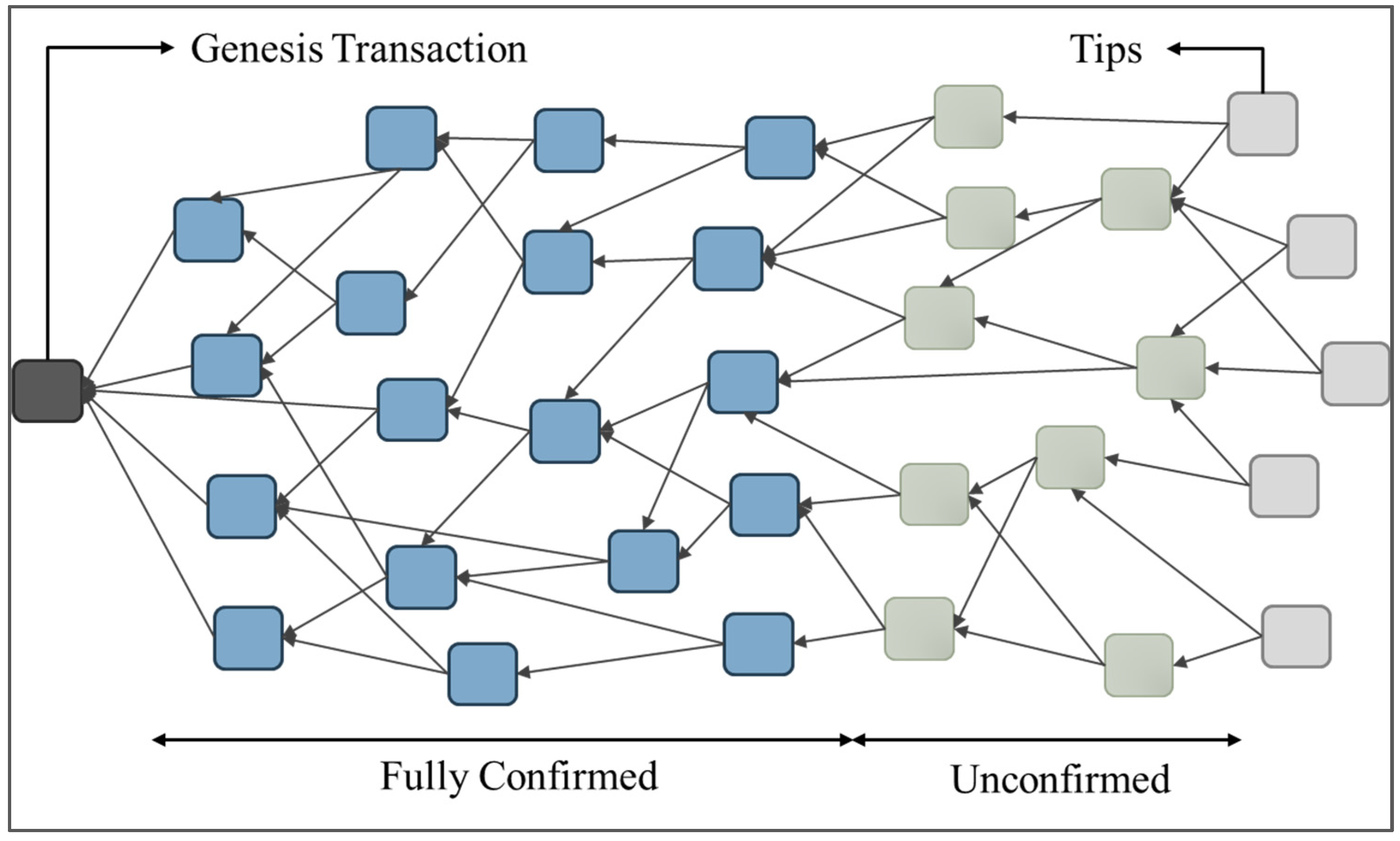
16]. Tangle is a net-like ledger structure. Additional transactions do not need to be specified behind which block, but multiple forks are allowed. They are added to the ledger by randomly selecting two transactions for verification. Therefore, transactions can be generated synchronously, which is much faster than traditional blockchains in terms of speed and scalability. As shown in
Figure 2, there are three types of transactions in the Tangle: confirmed, unconfirmed, and new transactions. The newly added transactions are called Tips. When a transaction in Tips is verified by other additional transactions, it becomes an unconfirmed transaction. When the unconfirmed transaction is continuously verified, and then all Tips can directly or indirectly refer to the unconfirmed transaction, the transaction becomes a confirmed transaction.
In the blockchain network, Satoshi Nakamoto divided networking into two roles: miners and users. Miners consume a lot of computing power to meet the proof of work (PoW) required to connect blocks. Motivation comes from the fees included in the transaction by the user. Such a reward structure is a major obstacle to the machine-to-machine economy, because the small payments between machines may be lower than the required fees. In IOTA, there is no difference between miners and users, and all nodes can participate in consensus. The person who initiates the transaction performs a lightweight proof of work, and the trader must verify other people’s transactions before uploading their own transactions. Therefore, when there are more users, the verification speed will be faster and the performance will be better. However, the blockchain will have a worse performance due to the larger the number of transactions. IOTA transfers the verification work from miners to users. In addition to preventing network congestion caused by a large number of spam transactions, it can also reduce the problem of excessive concentration of miners in certain areas. The technical functions of IOTA are as follows:
As the number of transactions increases, there will be more transactions available to approve previous transactions. Therefore, the transaction approval rate continues to increase, and the number of transactions and performance are directly proportional to the development.
- 2.
Zero transaction fees
Since there are no miners in IOTA, there are no transaction fees, which allows us to conduct microtransactions, that is, transactions of 1 cent without deductions.
- 3.
Quantum immunity
In order to prevent attackers from stealing users’ IOTA tokens, IOTA uses a quantum robust signature scheme called Winternitz One Time Signature, which can effectively prevent the possibility of signatures being cracked because they can only be used once.
- 4.
Secure data transmission
Every data transmitted using IOTA is encoded to ensure the safety of data storage, data transmission, or reference.
- 5.
Low resource requirements
Because IOTA is created to allow IoT devices to be easily connected to the chain, the amount of calculation for proof of work is not high, and the hardware requirements are not high.
The IOTA address is a string of 81 Trytes, which is generated by Seed. Each address corresponds to a unique private key to prove ownership to the node. The address is generated using Index and security level (an integer between 1 and 3). The same Index and security level will produce the same address. There are two types of addresses; the first is a one-time address, which is used for general valuable transactions, and is generated by using WOTS (Winternitz One Time Signature), and the other is a Merkle Root address, which is used for special applications such as MAM, and uses Merkle Hash Tree to produce WOTS. The address generation is shown in
Figure 3. Each private key corresponds to an address, which can be regarded as a pair of public key and private key. The Index of the private key starts from 0 and can have up to
253-1 index, which conforms to the maximum number of effective digits of IEEE 754-2008. Seed will first generate Sub-seed according to Index hash, and then hash Sub-seed according to the security level to generate private keys of different lengths. The length of the private key of security level 1 is 27 × 81 Trytes. The length of security level
2 is 2 × 27 × 81 Trytes. The length of safety level
3 is 3 × 27 × 81 Trytes. Then each
81 Trytes of the private key is formed into a segment, and 26 sponge function operations are performed respectively. Each 27 segment is called a Fragment. Finally, all Fragments are combined to perform a hash operation to generate a unique address.
In order to realize the potential of sharing secure and encrypted data streams, IOTA created a second layer solution called Masked Authenticated Messaging Protocol (MAM). In addition, IOTA is also developing an improved and more robust IOTA data layer, named Streams, which is developed based on MAM. MAM can use a lower cost method to trace the sensor data. Assuming that sensor data is published every 15 min without using MAM, then each message must be published to the same address. Past messages can be easily obtained by checking the data in the agreed address. However, the distributed ledger is publicly accessible. It is easy for an attacker to identify the data updated every 15 min and use a large number of spam transactions (Spam Transactions) to interfere with the reading of the data. Moreover, MAM can publish each message to a different address through the message chain (Message Chain), and use Root to obtain detailed information. The latter message cannot know the content of the previous message, and it can achieve forward secrecy. IOTA transactions are divided into two types, one is a valuable transaction, and the other is a valueless transaction. The MAM stores all sensor information by sending zero-value transactions to the Tangle, and connects the information stored in different addresses through Root.
Merkle-Tree Signature Scheme
MAM uses Merkle-tree Signature Scheme (MSS). This scheme combines one-time signature (OTS) and Merkle Hash Tree (MHT) [
17]. Through MSS, signatures can be quickly generated and verified, and quantum computing attacks can be resisted. MSS is generated by Seed. As shown in
Figure 4, the four cotyledons
A,
B,
C, and
D are the private keys generated by Index 0~3, respectively. After the private key is hashed once, the corresponding address will be generated, and then each group of two will be hashed in turn, and the root will be obtained after four hashing operations, and Root is the basis of MAM traceability data.
3. Our Proposed Scheme
This section will propose a lightweight identity authentication scheme, clearly describing the design process and architecture. The architecture designed in this paper includes three participants: Base Station (BS), Cluster Head (CH), and Sensor Node. Base Station is composed of two parts: Gateway and IOTA node. Gateway is responsible for confirming the identity of the Cluster Head and creating a whitelist and blacklist. IOTA node is responsible for synchronizing the ledger with other nodes and running a lightweight Proof of Work (PoW). Cluster Head runs MAM’s data upload and signature.
Figure 5 shows the system architecture of this paper. Sensor Node to Cluster Head uses MQTT communication protocol, and Cluster Head to Base Station uses TCP/IP communication protocol. Cluster Head acts as the MQTT Server. After collecting all the data transmitted by the Sensor Node, the data is packaged into a Bundle and transmitted to Base Station. In order to prevent Base Station from being attacked by DoS, Base Station must authenticate Cluster Head. Cluster Head will first register with Gateway, obtain temporary credential information, and use this credential to log in. While logging in, Cluster Head will pass the Root of the first transaction of MAM to Gateway. After Gateway confirms that the identity is correct, it will record the address of Cluster Head and the validity of the certificate, and wait for Cluster Head to upload the MAM data. When Gateway receives the request from Cluster Head to upload MAM, it will first verify whether the IP is correct and confirm that the certificate is still within the validity period. When the identity verification is correct, Gateway will pass MAM to the IOTA node intact, without changing the MAM Bundle content, and achieve the division of authority, Cluster Head manages the data, and Gateway manages the identity.
Because both the IOTA node and Gateway are in Base Station, Gateway can effectively protect the safety and reliability of the node. The IOTA’s only open port is 15,600. The purpose is to synchronize accounts with other nodes in the IOTA network. The nodes open 14,265 and 8081 internally, so that wireless sensor network data can be uploaded; and through 8081, the Dashboard function in the Port monitors the status of the node and views the contents of the ledger. Both Cluster Head and Gateway have the MAM Seeds, the Seeds of the two are not the same, and they do not know each other’s Seeds. Seed is equivalent to the private key of Ethereum and cannot be disclosed to the outside world. Cluster Head and Gateway Seed are managed by each, which can prevent Cluster Head or Gateway from being attacked. After the MAM data is stolen, the network must be rebuilt.
The current operating mechanism of IOTA 1.0 is to periodically take snapshots of the latest network, and delete the old snapshot data after a period of time, but only delete the zero-value transaction data. In the operation of the network, this approach can keep the network clean and efficient, and is in line with the actual use of the Internet of Things, without the need to trace data that is too long. For wireless sensor networks, it is sometimes necessary to view previous data. Therefore, in this paper, we set up a Chronicle on the Base Station and store long-term data by running a permanode. The previous condition for running Chronicle is that the Hornet node must be running at the same time. Therefore, this paper transfers the data in the Tangle account to the local NoSQL database by connecting to the Hornet node that is set up by itself.
This paper uses pre-configured keys to reduce the time and cost of key exchange, and only uses secure hash functions and symmetric keys for encryption.
Table 1 shows a list of symbols used in the entire proposed scheme. The scheme proposed in this paper consists of four stages: pre-configuration phase, registration phase, login phase, and secure communication phase. Next, we will introduce in detail one by one:
3.1. Pre-Configuration Phase
The key configuration server is set in the Base Station, and before the cluster head and sensor node are deployed, unique IDs are generated in advance for the cluster head and sensor nodes, and recorded in the memory. At this stage, the Base Station must first configure , , , , and , which are used to establish MAM of IOTA. BSseed must comply with IOTA’s Trytes rule: it consists of 81 characters, and each of them consists of {−1, 0, 1}. is the of MAM, and used to unlock the message stored in the Tangle. is the master key that generates Cluster Head and Sensor Node encryption keys, and is the ID used by the Base Station to identify the identity.
3.1.1. Information about the MAM Creation of the Base Station
The Base Station creates three MAM Channels to store different message data respectively, as shown in
Figure 6. Channel 1 stores the First Root of the Cluster Head and related information, which is used to track the information flow of the wireless sensor network. When the history data of a certain Cluster Head is needed, the Root and
of the Cluster Head are used to unlock the message flow. Channel 2 stores the node data of the wireless sensor network, and each Cluster Head has those Sensor Nodes. Channel 3 stores a list of malicious nodes, and records the MAC of the attacked or suspicious node in the Tangle. When a new Cluster Head or Sensor Node wants to join the wireless sensor network, the Base Station will first verify whether they are in the blacklist of Channel 3, if not, assign IDs to them, and record the node data in Channel 2. Each Channel uses different counts to generate different Merkle Hash Trees. As shown in Formula (1), different Root and Address are obtained, and different
are used for encryption.
3.1.2. Pre-Configured Data for Cluster Head
The Cluster Head collects sensor data and uploads it to the Tangle Network after encrypting and signing the data. Therefore, the Cluster Head must have a Seed to create a MAM message flow. In order to decrypt the data passed by the Sensor, the Cluster Head must also possess a decryption key. The master key
of the Cluster Head is generated as follows:
Sensor node pre-configured key.
Considering the computing power and storage space of the Sensor Node, The Sensor Node only has
SID,
CHID, and an encryption key
generated by the Base Station. The key generation method is as follows:
3.2. Registration Phase
The registration stage is to verify the identity of the Cluster Head, and then obtain a short certificate. The voucher can be used to log in after the Cluster Head as a reminder before uploading data. Because Cluster Head serves as the client node of MAM, it packs the message and uploads it directly to the Tangle node. The message will not be encrypted and decrypted in the middle so as to ensure the originality and integrity of the data. The signature verification of the data and attachment to the ledger are completed by the node, and the node uploads the data to verify two transactions first; these two transactions have nothing to do with the transaction uploaded by Cluster Head. The message verification of the Cluster Head is done by other nodes. Although this can ensure the fairness and integrity of the message, the Cluster Head still needs to perform identity verification to ensure the security of the wireless sensor network. Therefore, a short certificate is sent during the registration phase, so that the Base Station can confirm that the Cluster Head is a part of the network and has no other malicious nodes. The complete flowchart can be seen in
Figure 7. The steps of the registration phase are as follows:
Step 1
. Cluster Head gets its own timestamp
, and calculates
, and then encrypts the value after XOR with the symmetric key of Cluster Head, as shown in Formula (4). After the calculation is completed, the ID and encryption result are passed to the Base Station.
Step 2:
. When the Base Station receives the login request from the Cluster Head, it will first generate a decryption key
, as shown in Formula (5). Then the
of the Cluster Head is used to unlock the encrypted content and obtain the timestamp
of the Cluster Head, as shown in Formula (6). After that, Base Station will verify whether
is less than
, which is consistent with the time error of the transmission data. After the Base Station confirms that the Cluster Head identity is correct, the Base Station selects a certificate for the Cluster Head to expire
, and then calculate the false identity
, and generate temporary credentials
for the Cluster Head, as shown in Formulas (7) and (8). The Base Station generates
, encrypts the calculated
,
,
, and
together with
, and sends them back to the Cluster Head.
Step 3: After the Cluster Head receives the return value from the Base Station, it uses its own key to unlock the encrypted content, then verifies whether exceeds the time required for delivery, and stores the obtained , and for identity verification when logging in.
3.3. Login Phase
During the login phase, Cluster Head will generate the first MAM transaction and send the MAM Root to the Base Station. The Base Station will record the First Root of the Cluster Head and use it to track all transaction data on the wireless sensor network. The Cluster Head cannot be directly connected to the IOTA node in the Base Station. It must be authenticated and tracked through the Gateway. When Cluster Head logs in, it has not yet sent MAM transactions, but first signs and encrypts the transactions with Seed and
, and then informs Gateway in advance to send MAM messages. At this time, Gateway will verify whether the certificate of the Cluster Head is correct, and then record the IP to prepare for the secure communication of the Cluster Head. Cluster Head to Base Station uses the TCP/IP communication protocol, because the limitation of IOTA nodes is that only TLS nodes can connect and upload data, unless it is a local node upload transaction. However, the wireless sensor network transmits data over long distances, so the Base Station must have a TLS certificate. In
Figure 8 and
Figure 9, you can see the complete detailed process. The login steps are as follows:
Step 1: Cluster Head randomly selects a random number
that is not repeated, and meets the 81 Trytes character requirement of IOTA, and then selects the Restricted mode. Then the Seed, security level, mode, and
of the Cluster Head are packed into the format required by the Channel. Then Merkle Hash Tree is used to calculate Hash Root and Next Root, namely Formulas (9)–(11). Cluster Head packs the
obtained during registration into a Trytes format message, and then uses the Sponge function to perform calculations together with Next Root. Next, the Cluster Head uses Sponge Function to perform operations to generate a nonce value with a zero mantissa. In order to verify the transaction message, the Cluster Head first generates its own signature, and uses Sponge Function to perform operations on signature and sibling to generate an encrypted signature, as expressed in Formula (12). Then Cluster Head packs the
message,
nonce, and
encSig that have been calculated and converted into a payload, as shown in Formula (13). The payload is an additional message to initiate a zero-value transaction. The address of the transaction is different according to the different permission mode. The Cluster Head uses the Restricted mode, so the Address will be calculated by Sponge Function and encrypted with
, as expressed in Formula (14).
Step 2
. After the Cluster Head generates all the necessary information of the MAM, it needs to send the Root and
of the MAM to the Gateway. After obtaining this information, the Gateway can obtain the data of all the sensors of the Cluster Head. However, before sending data, the Cluster Head must first generate
, which is used by Gateway to verify whether the Cluster Head really has the credential data, as expressed in Formula (15). Then, the Cluster Head obtains
and attaches it to the encrypted content during transmission. The encrypted key is the symmetric key of the Cluster Head itself. Finally, Cluster Head sends back the identity information obtained during the previous registration to the Gateway together with the encrypted message.
Step 3: When the Base Station (Gateway) receives the login request of the Cluster Head, it will first verify whether
is overdue, and calculate
, as expressed in Formula (16). Then
is compared with the transmitted
to verify whether the validity of the voucher is correct. Next, Base Station uses
and
to calculate
, which is the current certificate of the Cluster Head, as expressed in Formula (17). The base station calculates
, as expressed in formula 18, which is used to verify whether the certificate of the Cluster Head is correct, that is, compare whether
and
are consistent. After the identity is confirmed, the Base Station can decrypt the contents of the Cluster Head.
Step 4
. When the certificate of the Base Station is correct and has not expired, the Base Station calculates
. Then
is used to unlock the encrypted message of Cluster Head, as expressed in Formulas (19) and (20). By decrypting the message of the Cluster Head, the Base Station can obtain the Root of the first message of the Cluster Head MAM and the
to unlock the transaction content. The Base Station saves the obtained
on the local server, and calculates the
, as expressed in Formula (21). Avoiding directly publishing the decryption key in the Tangle network, at the same time, you can check whether the hash value in the ledger is consistent with the value generated on the local side to verify whether the
stored on the local side has been tampered. The Base Station uploads the json generated by the Formula (22) to the Tangle ledger, as shown in the Channel 1 data in
Figure 8. At the same time, the Base Station records the IP and
of the Cluster Head as a whitelist for MAM connections. Finally, the Base Station sends back a confirmation prompt to the Cluster Head.
Step 5. When the Cluster Head receives the message returned by the Base Station, the Cluster Head will use its own key to unlock the encrypted content to obtain a message about whether the login is successful. After successfully logging in to the Base Station, the Cluster Head will send the of the first message to the Base Station. When the Base Station receives the message, it forwards the to the node; when it receives the login failure message, the Cluster Head re-registers and logs in until the login is successful. The purpose of login and registration is to simplify the transmission of MAM data. The data of the sensor is transmitted regularly and in large quantities. Too much identity verification will consume unnecessary resources. Therefore, the process of login and registration is simplified, and the transaction signature verification and value verification are handed over to other nodes to do the calculation of Proof of Work.
3.4. Secure Communication Phase
In the secure communication phase, the Sensor Node and Cluster Head are deployed. The Sensor Node can safely transmit the sensing data to the Cluster Head and send the data to the Tangle network through the Cluster Head, and then the Base Station monitors all the data of the wireless sensor network. The secure communication is divided into two parts. The first part is from the Sensor Node to the Cluster Head. The data is sent out through MQTT and the data in it is encrypted. The decryption key is dynamically generated by the Cluster Head, and there is no need to store the key in the Cluster Head, which saves the storage cost of the key. The second part is from the Cluster Head to the Base Station, using TCP/IP for transmission, and the encryption process uses the MAM protocol content, uses the Merkle-tree Signature method to sign, and authenticates through PoW. The complete process can be seen in
Figure 10. The detailed process of secure communication is as follows:
Step 1. When the sensor node wants to send data to the Cluster Head, it will pass the ID of the target Cluster Head, the ID of the Sensor Node itself, and the encrypted sensor content to the neighboring nodes. When the neighboring node is the target Cluster Head, the decryption key is generated, and the message content is unlocked; if the neighboring node is not the target Cluster Head, the neighboring node will pass the message to the node with the strongest signal. Because the decryption key for encrypted content can only be generated by the Cluster Head, even if the neighboring node obtains the encrypted content, the real content cannot be known. In order to avoid re-sending attacks, the encrypted content must be added with a timestamp , and the Cluster Head must calculate a reasonable transmission error time.
Step 2
. When the Cluster Head receives the data of the Sensor Node, it will generate a decryption key
, which is represented by the Formula (23). Using this decryption key to unlock the encrypted content,
and the sensor message
are obtained, as shown in Formula (24). Cluster Head will first check whether the message exceeds a reasonable transmission time, and after confirming that it is correct, it will upload the collected sensor data to the base station node. Cluster Head will first read the channel’s detailed information
, which is already generated when the first root is created during the login phase. Then
is used to calculate the Root and Next Root of the Merkle Tree, as shown in Formulas (25) and (26). Then, the
and
of the Cluster Head are put into the absorption function of Sponge Function, as expressed in Formula (27). Then, Cluster Head performs Sponge operation on the generated signature and the subtree of Merkle Tree, which is Formula (28). Next, perform Sponge calculations on
,
,
, and
respectively, and then package the results of the calculations into a
, as expressed in Formula (29). The generation method of Address is related to the selected mode. When the mode is Public, the Address is
. Because the mode selected by the Cluster Head is Restricted, Address must be processed with a sponge function and operated with
to generate an address in Trytes format, as expressed in Formula (30). After the Cluster Head has completed all the data calculations, it will initiate a zero-value transaction request to the Base Station. After receiving the message, the node of the base station will perform PoW on other transactions and append the result of the calculation to the transaction, so that the data is correctly uploaded to the Tangle ledger.
Step 3: When the Gateway in the Base Station receives the MAM message of the Cluster Head, it will first verify whether the IP location of the Cluster Head is recorded in the whitelist, and check whether the certificate owned by the Cluster Head has expired. When the IP is wrong or the certificate is invalid, Gateway will request Cluster Head to log in again or register the certificate information. If the identity is confirmed correctly, Gateway will forward the MAM data to the node of the Base Station. When the node receives the message, it will randomly search for two transactions in the ledger, namely Trunk and Branch, and verify the signature of the two transactions. Then PoW calculations are performed to find out their values, and finally these two transactions are appended to the message and filled in Timestamp at the same time. When the transaction is successfully added to the ledger, the Base Station will broadcast the transaction to other nodes. The base station can use the Cluster Head First Root stored in Channel 1 to query the past sensor data, but it can only be viewed. Only the Cluster Head can upload MAM messages to the Cluster Head Channel.
4. Security Analysis
This section will analyze the security of the method proposed in this paper. The security of the cluster head, the confidentiality of the data, and the integrity of the data are described further.
4.1. Forward Secrecy
The method proposed in this paper can have good forward secrecy. In terms of IOTA, because the Merkle Hash Tree of MAM is used to generate the next Root, only Seed knows the Root and Address of all messages. Here, MAM is to send zero-value transactions to store all messages. There is no correlation between transaction addresses, and all messages can only be traced through Root. Moreover, the previous message can know the next root, but the next message does not know the previous root, so it can achieve good forward secrecy. In terms of the perception layer, the method proposed in this paper uses a hash function to generate encryption and decryption keys. Only the upper-level resource-rich cluster head can unlock the message, and the sensor node cannot unlock the cluster-head encrypted content.
4.2. Replay Attack
Because the cluster head is registering and logging in, if it is obtained by an attacker, there will be doubts about re-sending attacks. For example, when registering, the ID of the cluster head is faked to obtain credentials. Although the content of the packet is not known, it can still be registered. However, the method proposed in this paper can effectively resist retransmission attacks. In terms of login, registration, and secure communication, this paper designs time-stamp TS parameters and speculates a reasonable transmission delay time, which can effectively prevent attackers from intercepting and sealing packets. The same packet is resent to the base station, the encrypted content of is designed in the registered packet, and the common key of the base station and the cluster head are used to encrypt; XOR operation is performed on the TS, and only the base station can obtain the encrypted TS. The login and secure communication are also protected by time stamps in the same way. When the base station or cluster head obtains the packet, in addition to judging the correctness of the timestamp, it also confirms the contents of the packet, whether the correct key and ID are used, and whether it is repeatedly transmitted in a short time, etc. The timestamp encryption method is as follows:
Cluster head registration.
The base station sends back certificate information.
Cluster head login.
The sensor node transmits the packet.
4.3. DoS Attack
Although the storage of transactions in the IOTA network is distributed, which can avoid problems such as single points of failure, the trust of nodes is a problem that must be considered. Because the nodes of IOTA are very lightweight, setting up nodes on their own can effectively solve the trust problem. Especially in the industrial control network, the internal network and the external network are not connected to each other, and the accounts can be synchronized to other nodes by setting up nodes, while maintaining integrity and privacy. Messages uploaded from WSNs to the Tangle have been verified twice: one is the identity verification of this paper, and the other is the IOTA transaction verification basic system. Because the IOTA node does not protect against DoS (Denial-of-Service) attacks, in WSNs, if an attacker uploads transaction information to the node in a short period of time, it may cause node failure. An effective solution is to establish multiple nodes for data split upload. Because the IOTA network will verify these transactions, we do not worry about whether the transaction information is correct. This paper proposes another solution, which is to establish a whitelist and blacklist mechanism. To verify the identity of the cluster head, the cluster head must first register and log in to obtain the qualification to upload transactions before uploading the MAM message to the base station. If the cluster head’s identity is in doubt, it will be blacklisted, and the identity card can only be uploaded again after ensuring the identity card. The identity verification steps are as follows:
Whitelist and blacklist mechanism. The identity of the cluster head must be verified and meet the identity that has been registered in the base station to upload data. In addition, the cluster head detected as a malicious device cannot perform any operations on the base station.
IOTA transaction signature verification. Each identity in the IOTA network is unique, and the nodes in the network verify each other’s identities. When a self-built node is attacked, the identity verification process will not disappear, but will be executed by other nodes in the network, which can ensure that identity verification is not interrupted. In addition, the data stored on the network will not disappear.
4.4. Sybil Attack
Sybil Attacks may cause many problems, such as inconsistent network information, and the method in this paper can resist such attacks. The cluster head and base station designed in this paper have their own Seed, so when the attack wants to impersonate the identity, it will fail because the attacker does not know the Seed and cannot sign the message content. Because Seed is the identity ID of IOTA, transaction messages can be published through Seed, and the Bundle can be signed to ensure the validity of the transaction. The MAM contains content such as , etc. Only those with Seed can publish MAM, generate encrypted , and generate the next Root. In this way, you can ensure that your identity is not forged. In the architecture designed in this paper, base stations, cluster heads, and sensor nodes all have different identity IDs. If an attacker wants to impersonate a fake identity and modify the content of IOTA, he must impersonate the identity of WSNs and the identity of IOTA at the same time. The difficulty and cost are relatively high, so this attack can be resisted.
4.5. Data Security and Preservation
Blockchain is considered as a secure decentralized ledger because it uses complex cryptography, Bitcoin in particular itself is rarely attacked. However, with the advent of quantum computers, cryptographic technologies such as SHA-256 and RSA will be cracked. IOTA uses WOTS to sign, which is a secure signature, and can effectively resist quantum computing, so it can ensure that the content in the Tangle is intact and protected from tampering. In addition, in the method designed in this paper, the cluster head and the MAM seed of the base station are stored separately. Assuming that the cluster head is attacked, only a new seed and encryption key need to be regenerated without rebuilding the network. When the base station is attacked, only the network key needs to be re-assigned. The data stored in the Tangle is still safe, because the seed of the cluster head is controlled by the cluster head itself, and the base station cannot modify the content of the cluster head to ensure data from the perception layer to the safety and security of the Tangle.
4.6. Eavesdropping Attack
Because the decryption key is pre-configured in all sensing devices, the attacker cannot obtain the encrypted content under the protection of the sensing device, and when the attacker cannot obtain the encryption key, the attacker cannot forge false information. IOTA’s MAM messages are encrypted using . In the part of secure communication, the randomly selects a random number of 81Trytes that is not repeated by the cluster head. During the login phase of the cluster head, the cluster head encrypts using , and transmits the encrypted message to the base station, so only the base station and the cluster head can solve the problem, and open the encrypted content of MAM. In addition, when the attacker does not know the Seed, he cannot modify the packet content, which can ensure the concealment of the data from the generation to the cloud. The designed in this paper is transmitted from the cluster head to the base station during the login phase, and uses a symmetric key to encrypt . Therefore, only the base station and the cluster head know the sensor content. Even if the attacker knows the , the content cannot be modified, because only the seed owner can modify it, and if the cluster head changes the to log in again, the attacker will get a useless .


