1. Introduction
Vibration analysis of structures with cracks has been a long-standing topic of research interest. Establishing the influence of a crack on a structure’s dynamic characteristics in advance can help avoid catastrophic failures. Monitoring of vibration parameters is often used in structural health monitoring, as demonstrated in a review by Yang et al. [
1]. The assumed modes method is a useful analytical method used to estimate the dynamic characteristics of a structure, where the choice of assumed mode is an important consideration to the utility of the method. Meirovitch [
2] presented a modern treatment for vibration analysis and developed various mathematical approaches emphasizing analytical and computational solutions. However, certain choices of assumed modes, in particular the system eigenfunctions, can lead to ill-conditioning and other numerical difficulties. To address this shortcoming, Monterrubio and Ilanko [
3,
4] presented a set of admissible functions which may be used in the assumed mode method. In their approach, alternative admissible functions were proposed in place of the traditional eigenfunctions, and penalty function terms were added to the model constraints to account for the boundary conditions. The proposed set of functions do not lead to ill-conditioning while handling a large number of terms. Hosseini and Baddour [
5] used the set of functions developed in [
3] with the penalty function method to study the vibrations of a beam with lumped attachments. Boundary conditions were enforced using penalty terms. Kateel and Baddour [
6] adopted the set of functions, furthering the study on the effectiveness of the set of functions for beams with various boundary conditions viz., simply supported, clamped–clamped and clamped–free boundary conditions. It was concluded that the selected set of boundary penalty values depends on the underlying beam properties and the boundary conditions of the problem. A crack in a beam causes a change in the local stiffness of a structure, and hence a change in the dynamic characteristics such as natural frequencies and mode shapes. Doebling et al. [
7] presented a comprehensive literature review on the identification of structural damage using measured vibrational data. There are two primary approaches to modelling cracks in beam structures that have been documented in the literature: local stiffness reduction and a discrete spring model. Ostachowicz and Kalwczak [
8] presented an analytical study of a cracked cantilever beam. The crack was modelled using a stress intensity factor, and it was assumed that there is decrease in elastic deformation of energy in the plane stress of the beam. Chondros et al. [
9] developed a continuous cracked bar vibration model for a Euler–Bernoulli cantilever beam with a crack. The crack was assumed to be an edge crack and was modelled as continuous flexibility. Using a stress intensity factor and Castigliano’s theorem, the differential equation for the cracked beam was developed. It was suggested that the continuous cracked beam theory holds applications for other cracked structures. Yang et al. [
10] developed a numerical model to evaluate the dynamic characteristics of a cracked beam. The crack was assumed to be an open crack and modelled using the strain energy. A simply supported and a fixed–fixed beam were considered for the study of the proposed model. Dahak et al. [
11] presented a method to identify and quantify of cracks in beams using natural frequencies. The stiffness matrix was calculated by the theory of fracture mechanics, by inverting the flexibility matrix. Experimental results were compared and validated. Khnaijar and Benamar [
12] developed a discrete cracked beam model for multiple cracks. The beam bending stiffness was represented as multiple spiral springs representing the crack model and connected by bars.
Using approaches such as stress intensity factor, many attempts have been made in identifying the size, location, and depth of a crack in a beam. Qian et al. [
13] proposed a simple method to determine the crack location based on the relationship between the crack and the eigencouple. The crack was assumed to be an edge-crack on a cantilever beam. Using the stress intensity factor and the finite element method, the stiffness matrix of the cracked beam was developed. The proposed method was suggested for complex structures with known stress intensity factors. Kam and Lee [
14] presented an alternative approach for a non-destructive method to identify the size of the crack for a given location of the crack in the structure. The crack was modelled as in [
13]. The strain energy of the uncracked and cracked beam was utilized to determine the crack size iteratively. The effect of the presence of the crack on the structural strain energy was obtained based on fracture mechanics. The study was carried out for different beams and frame structures. The proposed method was verified with the Finite Element Method (FEM). Sinha et al. [
15] proposed a simplified crack modelling approach using an FEM approach for the estimation of crack depth and location. The crack was modelled using the concept of change in stress and strain in the vicinity of the crack section. The study used Euler–Bernoulli beam elements with minor modifications to the local flexibility in the vicinity of cracks. Arem [
16] reported a standard and generic methodology describing the technique of construction of a cracked beam finite element. Validation of the approach under static loading was given for a cantilever beam with one and two cracked transverse sections.
Yoon et al. [
17] demonstrated the influence of two open cracks on the dynamic behavior of a double cracked simply supported beam. A Euler–Bernoulli beam represented by spatial mode functions was considered and the beam was sectioned into three parts. Shifrin and Ruotolo [
18] proposed a new technique to calculate the eigenvalues of a cracked beam and suggested that the proposed method yields reduced computation time by decreasing the matrix size. Chondros and Dimarogonas [
19] investigated the relationship between natural frequency of a cracked beam and the depth of a crack. A cantilever beam was welded at a clamped end, and a crack on the welded end was studied. The crack was modelled as a torsional spring and assumed to be a transverse surface crack. Liang et al. [
20] demonstrated a method for quantitative assessment of a beam with a crack and provided an extension to the work for multiple damages. Local flexibility in the vicinity of the crack was developed using a massless rotational spring. Lee and Ng [
21] used the assumed modes method to estimate the eigenvalues and eigenvectors of a simply supported Euler–Bernoulli beam with single-sided crack and a pair of double-sided cracks. The crack was modelled as a torsional spring and a linear spring to account for the transverse deflection at the crack. Khiem and Lien [
22] developed a new method for the dynamic analysis of a beam with an arbitrary number of cracks. The crack was modelled as a rotational spring. Adams et al. [
23] evaluated a non-destructive method to study the integrity of structures. A reduced local stiffness and massless spring model was considered for the modelling of the crack. The model was considered for the study due to its simple applicability.
Long et al. [
24] demonstrated the influence of the partial crack closure to model the stiffness variation of the cracked beam. A finite element model of a beam with a breathing crack, using the multiple-scale method was proposed to analyze the nonlinear vibration of a cracked beam subjected to harmonic excitation. It was that the nonlinear responses of a beam with a breathing crack are affected by both the structural parameters and the crack parameters. Afshari and Inman [
25] considered a Euler–Bernoulli Beam with a single crack attached with piezoelectric patch. A new formulation for a beam with a shallow crack was demonstrated using the Rayleigh–Ritz method for health monitoring. The crack was modelled as a massless rotational spring to account for the loss of energy. The proposed methodology was demonstrated to be suitable for use with the assumed modes method. In their assumed modes approach, the eigenfunctions of the uncracked beam were used. The study was carried out for simply supported and clamped–clamped boundary conditions for different crack depth ratios and normalized locations. Dimarogonas [
26] defined the torsional spring constant in the vicinity of the cracked section of the beam when a crack of uniform depth exists.
The literature review reveals that many attempts have been made by researchers to accommodate the various crack models. Most approaches divide the beam into sub-beams connected at the crack. This requires the entire system to be remodeled if the crack location changes. In particular, if an assumed modes method was used, this requires separate sets of assumed modes functions for the sub-beams, and then enforcing continuity at the crack, increasing the complexity of the computation. For research that has used an assumed mode approach for the entire beam, such as in [
25], the traditional beam eigenfunctions were used, thereby necessitating remodeling if the boundary conditions are changed. In short, current approaches in the literature require extensive remodeling when crack parameters and/or boundary conditions of the beam change.
The present paper proposes the use of Alternative Admissible Functions (AAF) to address the need to easily modify the system model with changes in boundary conditions and/or crack parameters. An analytical method is proposed to determine the eigenvalues and eigenfunctions of a beam with a shallow crack. The crack is modelled as a penalty function to account for the local stiffness reduction in the system due to its presence. This modelling approach is advantageous as it maintains beam continuity and limits system remodeling with changes in crack parameters or boundary conditions. The mass, stiffness, and penalty function matrices for various boundary conditions are developed and are used for the analysis of a beam with a shallow crack. Due to the presence of the crack, the stiffness matrix of the unconstrained beam is altered, and the effective stiffness of the beam with a crack is calculated. The eigenvalues and eigenfunctions for the beam with a shallow crack for various locations and crack depth ratios are determined by constructing the equation of motion. The study is conducted for both symmetrical Simply Supported (SS), Clamped–Clamped (CC) boundary conditions, and asymmetrical Clamped–Free (CF) boundary conditions.
2. Methodology
The Alternative Admissible Functions (AAF) approach for modelling a beam with a shallow crack to determine dynamic characteristics is established in this section. The formulation for an uncracked beam is established first, followed by the applicability of boundary penalty functions, and finally inclusion of a shallow crack into the beam. The choice of AAF in this approach does not alter as the beam boundary conditions and crack properties change. The changes in the boundary conditions and crack properties are modelled via a separate set of penalties, which imparts flexibility and ease of use to the method. The beam is considered as a continuous system and with the inclusion of the crack, the continuity is maintained by the using the same set of functions throughout the beam. The proposed approach is validated by comparing the natural frequency and modeshape values from the literature.
2.1. Alternative Admissible Function Method
The chosen set of
AAF,
, consist of a set of simple polynomials and trigonometric functions, and were first proposed by Monterrubio and Ilanko [
3] for modelling vibrations in beams, plates, and shells. The set of admissible functions,
, are given by
where
x is the axial coordinate of the beam,
L is the beam length, and
N is the number of terms included in the set of admissible functions. The selected set of alternative admissible functions have been demonstrated to be easy to compute and numerically well behaved [
6] for applications to beams. The choice of the set of admissible functions presented in Equation (1) is such that the functions can best represent the eigenvectors of a structure in an unconstrained condition [
3,
4]. Notably, the chosen set of assumed modes are non-symmetrical in space, as shown in
Figure 1.
Further, the advantage of this selected set of admissible functions is that it can be used with different boundary conditions without altering the choice of assumed mode functions for various boundary conditions. This is in contrast to the traditional approach to assumed modes, where the form of the assumed modes is often changed to account for a change in boundary conditions. For the assumed modes method, the transverse displacement
w (
x,
t) of the oscillations of a Euler–Bernoulli beam is modelled as
where
x is the position along the beam,
t is time, and
ω is the frequency of vibration. The spatial function,
W(
x), is assumed to be a sum of the assumed-modes and to have the form given by
where
(
x) is the set of chosen
AAF and
are constants. The variable
N is the number of chosen assumed modes and determines the dimensionality of the model.
Knowing the system parameters such as the mechanical properties (Young’s modulus
E and density per unit length of the beam,
ρ) and geometrical parameters (length
L, width
b, and height
h), then the maximum kinetic energy (
Tmax) and maximum potential energy (
Vmax) of the unconstrained system can be written in terms of the admissible functions as
and
where
I is the second moment of area of the cross section. For a conservative system, ignoring the damping, it follows that
Applying the Rayleigh–Ritz minimization to the conservative system leads to the derivation of mass and stiffness matrices via
where
is the normalized maximum kinetic energy function to be minimized.
On solving Equation (7) results in a set of
N algebraic equations whose equivalent matrix representation yields
Vector
is the vector of coefficients from Equation (3). The mass and stiffness matrices can be represented in the forms of alternative admissible functions, respectively as
and,
where
denote the coefficients of mass matrix
M and
denote coefficients of the stiffness matrix,
K. The present method (
AAF) provides the flexibility to model the system with different boundary conditions without the need to remodel the system’s mass matrix,
M and the stiffness matrix,
K with any change in boundary conditions.
2.2. Boundary Penalty Functions
As the
AAF do not themselves satisfy the boundary conditions, the boundary conditions are addressed by introducing appropriate virtual stiffnesses represented via linear springs (
) and rotational springs (
) at the boundaries and termed as boundary penalty functions. The total system potential energy is altered due to the addition of the boundary penalty terms. Most generally, the penalty function associated with the potential energy of virtual springs on the boundary is given by
Incorporating the assumed modes of Equation (3) into (11) and following the procedure outlined previously results in the boundary penalty stiffness matrix of the system. The symmetric penalty stiffness matrix is given by
The first two terms in Equation (12) indicate the virtual linear springs (k0) and next two terms indicate the virtual rotational springs (kr0) at the boundaries of the beam. The virtual linear springs and the rotational springs restrict vertical and rotational movements, thereby enabling the implementation of various boundary conditions. Depending on the boundary conditions of the problem, a combination of appropriate virtual spring elements can be included to produce the penalty stiffness matrix in Equation (12), which is then added to the unconstrainted beam stiffness matrix.
In the present work, the penalty stiffness matrix associated with three commonly used boundary conditions, i.e., Clamped–Free (CF), Simply Supported (SS) and Clamped–Clamped (CC) are reported.
For a
CF beam, the energy of the virtual linear spring is represented by
and constrains the vertical movement of the beam. Meanwhile,
represents the rotational spring energy and constrains the rotation of the beam. The penalty stiffness matrix for
CF boundary condition is represented as
In this study, the first three natural frequencies and mode shapes are investigated. The number of terms should be double the number of frequencies of interest, according to Meirovitch [
2]. The smallest set in the set of
AAF that may cover at least two polynomial and two trigonometric functions is used for illustration purposes, and therefore
N = 5. The matrix form of Equation (13) is given as
It is noted that although the CF boundary condition does not possess left/right symmetry, the penalty stiffness matrix for the CF boundary condition is still a symmetric matrix. This follows as the penalty stiffness matrix is a matrix implementation of both boundary conditions.
Similarly, in Equation (15),
and
, impose the virtual linear springs at
x = 0 and
. These constrain the vertical movement of the beam at the left and right-side boundary conditions for the
SS beam and result in a penalty matrix with entries given by
For
N = 5, the penalty stiffness matrix form of Equation (15) is given as
It can be noticed that the penalty matrix for the simply supported beam is symmetrical in nature and has only virtual linear springs on both the ends, as the beam is only constrained to move vertically and can rotate freely at the boundaries.
For a
CC boundary condition, a combination of virtual linear spring and virtual rotational spring are symmetrically imposed on both ends of the beam. The
and
represent the virtual linear springs and virtual rotational spring at the
x = 0 end, respectively. The
and
represent the virtual linear springs and virtual rotational spring at the
x = L end, respectively. Thus, the entries of the boundary penalty stiffness matrix for
CC are given by
For
N = 5, the penalty stiffness matrix for
CC boundary condition is given as
The virtual linear and rotational springs appear in a symmetrical manner in Equation (18), as the CC beam is constrained symmetrically at both the ends.
The obtained penalty terms for different boundary conditions are then summed with the unconstrained stiffness matrix of the unconstrained beam, as well as the stiffness matrix due to the presence of the crack to obtain the effective total system stiffness matrix. The modelling of the cracked portion of the beam is reported in the following section.
2.3. Crack Modelling
The established mass, stiffness, and penalty function matrices for various boundary conditions are used for the analysis of the beam with a shallow crack. The crack is then also modelled as a penalty function to account for the local stiffness reduction.
Figure 2 shows a Euler–Bernoulli beam with a shallow crack. The dimensions of the beam are represented by length
L, breadth
b, thickness
h and a shallow crack at a distance
xc from one end of the beam.
The magnified view of the shallow crack location in the beam is shown in
Figure 3. The depth of crack is denoted by
dc. The crack is represented as a massless rotational spring [
25] due to its simplicity, adaptability.
The
AAF of the uncracked beam is used to model the assumed modes of the beam with a shallow crack. The presence of a crack reduces stiffness and leads to a loss of potential energy [
25]. This reduction is included by modifying the potential energy of the cracked beam. The energy loss is proportional to the amount of added flexibility in the beam. To quantify the added flexibility, the crack is modeled as a penalty function. The virtual linear stiffness at the location of the crack is assumed to be negligible and the virtual rotational stiffness at the location of the crack is considered as a massless rotational spring (
kc).
The compliance of the crack (
Cc) of the virtual rotational stiffness at the location of the crack is given by the Afshari and Inman approach [
25] as
where
EI is the flexural rigidity of the beam. The values of the function
α for different crack depth ratios in the range of
is established in Afshari and Inman [
25] and expressed as
The potential energy due to the presence of the crack can be quantified as [
25]
where the effective compliance of crack
, is given as
.The potential energy is proportional to the added compliance due to the presence of the crack and the added rotation. The (modified) potential energy of the cracked beam is formulated by
subtracting the potential energy due to the presence of the crack in Equation (18) from the potential energy of the unconstrained beam as given in Equation (5). The modified potential energy (
) of the beam in the presence of crack is then given by
The effective stiffness for the traverse vibrations of the cracked beam matrices is obtained using the maximum modified potential energy via Rayleigh–Ritz minimization and is given as
The first part of Equation (23) accounts for the unconstrained beam stiffness and the second part accounts for the reduction in stiffness due the presence of the crack. The stiffness matrix of the cracked beam portion alone is expressed as
Equation (24) can be expressed in matrix form for
N = 5 as,
In the following section, the equation of motion of the beam with a shallow crack is established.
2.4. Equation of Motion of a Beam with a Shallow Crack
The frequency equation for a beam with a shallow crack takes the generalized matrix form as
Equation (26) can be simplified as
where
K and
M are the generalized unconstrained beam stiffness and mass matrices of size
N ×
N, respectively.
KP is the penalty matrix depending on the type of boundary to be enforced and detailed under
Section 2.2,
is the stiffness matrix due to the presence of the crack, and
is the effective stiffness matrix of the cracked beam (beam with a shallow crack only, without boundary conditions).
For
N = 5, using Equations (9) and (10), the
M and
K matrices take the matrix form as
and
The effective stiffness matrix of the cracked beam (beam with crack only, without the boundary conditions) is given by
and where
.
It can be noticed that the effective stiffness matrix in Equation (30) involves the location of the crack, xc, and the crack depth ratio, . The advantage of modelling the crack as a penalty is that it can easily be enforced in a beam with different boundary conditions directly for any location of crack and crack depth ratio.
For a non-trivial solution of Equation (27), the determinant of the coefficients of
C must be equal to zero, hence
Equation (28) is used to estimate the natural frequencies and mode shapes of a beam with a shallow crack at different location and depth ratio, using appropriate Kp depending on the boundary conditions of interest.
3. Results
The validation of the proposed approach is carried out for the three boundary conditions viz., SS, CC, and CF using Equation (24), for a beam with a shallow crack. The first three natural frequencies and modeshapes are evaluated and reported for different location and crack depth ratio.
3.1. System Parameters
The geometrical parameters and material properties of Afshari and Inman [
25] are tabulated in
Table 1 and used for validation. The present method is validated with information available in Afshari and Inman [
25], i.e., results for symmetrical boundary conditions viz., Simply Supported (
SS) and Clamped–Clamped (
CC). Validation for the Clamped–Free (
CF) boundary condition with a shallow crack in estimating the natural frequency and modeshapes is via comparison with results in Khnaijar and Benamar [
12].
The normalized crack position considered in the literature is varied from 0.2 to 0.8 times the total length of the beam, and the crack depth ratios are from 0.2 to 0.6. The following section provides validation of results for SS and CC cracked beam. Matlab code is generated to solve the eigenproblem.
3.2. Validation of Simply Supported Beam with a Shallow Crack
The geometrical parameters and material properties tabulated in
Table 1 are used to model an
SS beam. The boundary penalty function value is selected based on the range of values used in previous work [
3,
6] and is considered as
. Upon substituting the value of
in Equation (13),
is evaluated. Using Equation (27), the effective stiffness matrix
of the beam with a shallow crack for the chosen system parameters is obtained. On substituting the expression for
and
M in Equation (28), the natural frequencies of the
SS beam with shallow crack are evaluated.
Table 2 shows the evaluated first three natural frequencies of an
SS beam with shallow crack for a normalized crack positions of 0.2, 0.4, 0.6, and 0.8 from one end, and with a crack depth ratio of 0.2. The second and the third column tabulate the natural frequency using the Afshari and Inman [
25] approach and the proposed
AAF method, respectively. The fourth column tabulates the percentage error in predicting the natural frequency using the present approach.
It can be noticed that the results obtained are in good agreement with the results from Afshari and Inman approach [
25] and the errors are less than 1%. As the boundary penalties are symmetric for the
SS boundary condition and due to symmetry in crack position, the results for pairs of cracks present at normalized positions of 0.2 and 0.8, and 0.4 and 0.6, are the same. As the location of the crack moves towards the center of the beam, a trend of a decrease in the first natural frequency, increase in the second and third natural frequency as reported in the literature is observed using the present approach.
Similarly, the natural frequencies for crack depth ratio of 0.4 at four different normalized crack positions are obtained and tabulated in
Table 3. It is noticed that estimated natural frequencies using the
AAF method are in good agreement with the reported literature. It can be observed that the percentage error in predicting the natural frequency is larger for the first mode as the normalized location of the crack moves closer to the boundaries compared to the second and third mode. This type of trend could be due to the asymmetric nature of beam due the presence of crack and selected boundary penalty value. In the present study, the boundary penalty value for both uncracked and cracked beam was chosen to be the same. As the predicted natural frequency using the
AAF approach is higher for the first mode compared to Afshari and Inman [
25], this may indicate that the selected boundary penalty value is high and can be tuned by considering the crack.
It can be concluded that the present method can predict the natural frequencies for different normalized positions and crack-depth ratio. The percentage of error is less than 1% and has a similar type of trend about the center of the beam, as indicated for a crack depth ratio of 0.2.
The corresponding mode shapes of natural frequencies tabulated in
Table 2 and
Table 3 are generated and shown in
Figure 4 and
Figure 5, respectively. The solid lines indicate the modeshapes obtained via Alternative Admissible Function using the uncracked beam systems (
AAF), and the dashed lines indicate the modeshapes of the reference model. The first mode is indicated by blue color, the second mode is indicated by red, and black depicts the third mode of the beam. The stated legend applies to
Figure 4,
Figure 5,
Figure 6,
Figure 7 and
Figure 8. The
SS boundary conditions modeshapes are validated with reference model of Afshari and Inman approach [
25].
Figure 4 represents the modeshapes of an
SS beam with a shallow crack at different normalized location and crack depth ratio (
dc/
h) = 0.2. It is noted that the present approach can produce accurate modeshapes for the symmetrical
SS boundary condition. The
AAF method is simple to compute and generate eigenvalues without the need for remodeling the system.
Figure 5 represents the modeshapes of an
SS beam with a shallow crack at different normalized location and crack depth ratio (
dc/
h) = 0.4.
By visual examination of these plots, it is observed that at the boundaries the lateral motion is restricted, and the rotational motion is allowed to satisfy the
SS beam boundary condition. It is noticed that the present crack modelling approach used with
AAF method satisfies the boundary condition while generating the modeshapes for different normalized locations of crack and crack depth ratios. In
Figure 4 and
Figure 5, the modeshapes are in symmetry for normalized crack location of 0.2 and 0.8, and 0.4 and 0.6. The next section reports and discusses the validation of results obtained for
CC boundary conditions.
3.3. Validation of Clamped–Clamped Beam with a Shallow Crack
Having obtained a good agreement in results for
SS boundary condition, the work is extended to validate the results for
CC boundary conditions using the
AAF method. The geometrical parameters and material properties tabulated in
Table 1 is used to model a
CC beam. The boundary penalty function value is selected based on the range of values used in previous work [
3,
6] and is considered as
. Upon substituting the value of
in Equation (15),
can be evaluated. Using Equation (27), the effective stiffness matrix
of the beam with a shallow crack for the present system parameters are evaluated. On substituting the expression for
and
M in Equation (28), the natural frequencies of the
SS beam with a shallow crack can be evaluated.
Table 4 tabulates the first three natural frequencies of
CC beam with shallow crack for a normalized crack positions of 0.2, 0.4, 0.6, and 0.8 from one end, with a crack depth ratio of 0.2.
It is noticed that the results obtained are in good agreement with the results considered for comparison [
25] and the errors are less than 1%. Similarly, the natural frequencies for crack depth ratio of 0.4 at four different normalized crack positions are obtained and tabulated in
Table 5.
In
Table 4 and
Table 5, it is observed that the percentage error in predicting the natural frequency for the first and second mode is higher compared to the third mode as the location of the crack approaches the boundary. Due to symmetric values of boundary penalties, the symmetry in the results for normalized positions of 0.2 and 0.8, and 0.4 and 0.6 are the same, as expected. The percentage error decreases as the normalized crack position moves towards the boundaries for third mode and second mode. Meanwhile, the percentage error in predicting the natural frequency increases for the first mode as the normalized crack location moves towards the clamped–clamped condition.
In the present study, the boundary penalty value for both uncracked and cracked beam is considered the same. As the predicted natural frequency using
AAF approach is higher for all three modes compared to Afshari and Inman [
25], this may indicate that the selected symmetric boundary penalty value is higher and can be tuned by considering the effect of the crack which induces asymmetry in the beam. Validation carried out for symmetrical boundary conditions, i.e.,
SS and
CC boundary conditions yields excellent results in good agreement with the reported literature. It indicates that the crack as a penalty function model is well suited to accurately evaluate the natural frequencies for different boundary conditions for shallow cracks. The selected boundary penalty value has scope for tuning by considering the effect of crack on the boundaries.
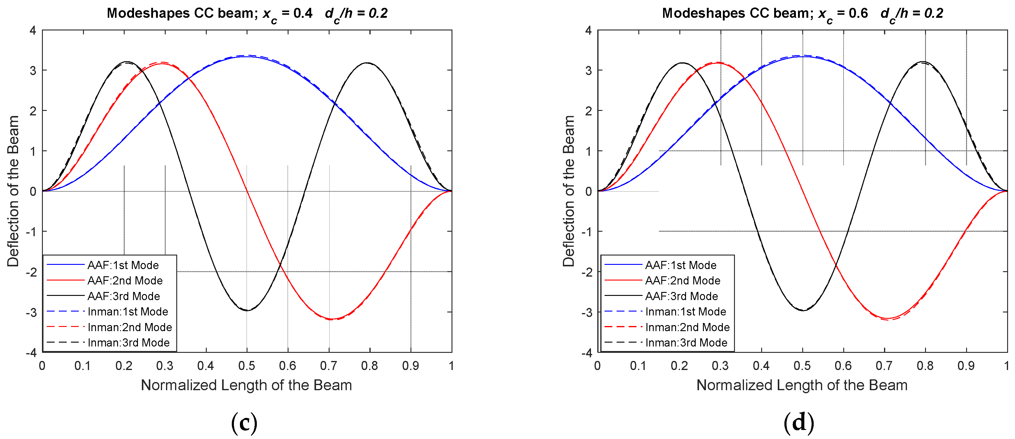
To validate the proposed approach for modeshape calculation of a
CC beam with shallow crack, the modeshapes for different normalized location and crack depth ratio of 0.2 are depicted in
Figure 6.
In
Figure 6, it is noticed that the boundary conditions exhibited by the
CC boundary condition is satisfied by the proposed method. At the clamped end of the beam, the rotational and the lateral motion are restricted and are clearly depicted in the modeshapes. An excellent agreement with the reference model Afshari and Inman approach [
25] is observed. Similarly, in
Figure 7, the modeshapes of a
CC beam for different normalized locations and crack depth ratio of 0.4 are shown.
As observed in
Figure 7, the modes shapes have a mirror image for normalized crack location of 0.2 and 0.8, and 0.4 and 0.6. This indicates the selected set of
AAF, with boundary penalties and a crack model as penalty method, produces the predicted behaviors for both the
SS and
CC boundary conditions. The proposed approach can be used to generate modeshapes for different crack locations and depth ratio efficiently for symmetrical boundary conditions. The advantage of the present approach is the ease to model different boundary conditions and crack parameters without the need to remodel the entire system.
3.4. Validation of Clamped–Free Beam with a Shallow Crack
To measure the efficiency of the present method, the work is extended to an asymmetrical boundary condition. A Clamped–Free Beam implies the need for asymmetrical boundary penalty terms due to the free end. This provides an excellent platform to validate the proposed approach. Validation for the
CF boundary condition with a shallow crack is carried out and compared with results in Khnaijar and Benamar [
12]. The geometrical and material properties used for validation are tabulated in
Table 6.
The geometrical parameters and material properties tabulated in
Table 6 are used to model a
CF beam. The boundary penalty value is considered as
. Upon substituting the value of
in Equation (11),
can be evaluated. Using the same methodology for
SS and
CC, the natural frequencies of the
CF beam with a shallow crack can be evaluated. Khnaijar and Benamar [
12] reported first two natural frequencies and
Table 7 tabulates the first two natural frequencies estimated using the
AAF approach of a
CF beam with shallow crack for normalized crack positions of 0.25, 0.50, and 0.75 from the fixed end, with a crack depth ratio of 0.5.
It is observed that there is an increase in the percentage error for the fundamental natural frequency as the position of the crack moves towards the fixed end. A similar trend is observed in the case of SS and CC boundary conditions. The second natural frequency has the slightly higher percentage error for the crack at the midpoint of the beam. This indicates a scope for adjustment of the boundary penalty values by considering the effect of the crack.
Using the crack as a penalty model approach shows an acceptable agreement. Comparing with results from with Khnaijar and Benamar [
12], there is less than 3% error in predicting the natural frequency. The present crack as a penalty approach provides flexibility in relocating the crack without the need to reformulate the whole problem to estimate natural frequencies. The traditional assumed modes include trigonometric functions and hyperbolic functions, leading to computational instability. The present
AAF with penalty approach uses lower order polynomials and cosine series, increasing the computation efficiency.
The method is further validated for generating asymmetrical
CF boundary conditions mode shapes to compare with Khnaijar and Benamar [
12]. In
Figure 8, the crack depth ratio is kept constant at 0.5 and the modeshape is derived for three normalized crack positions.
Symmetry is observed for normalized crack location 0.25 and 0.75. The CF boundary condition is an example of asymmetrical boundary condition, and the proposed method satisfies the CF boundary conditions.
The present approach provides promising results for both symmetrical and asymmetrical boundary conditions and can be used to derive modeshapes for various normalized shallow crack locations.
4. Conclusions
In this paper, a methodology using assumed modes with Alternative Admissible Functions (
AAF) and a penalty function was proposed for modelling a beam with a shallow crack. In this method, the boundary conditions and the crack are modelled as pairs of virtual linear and rotational springs. For the crack, the effect of the virtual linear spring is assumed to be negligible, and the virtual rotational spring is modelled as a massless rotational spring. The loss of energy due to the presence of the crack is accommodated by modifying the potential energy of the beam. Using this method, the dynamic characteristics of the beam of both symmetrical and asymmetrical, i.e., Simply Supported (
SS), Clamped–Clamped (
CC), and Clamped–Free (
CF) boundary conditions are validated with results found in the literature. The obtained results show excellent agreement with previous literature results. In the case of
SS and
CC boundary conditions, the obtained natural frequency values indicate a symmetry for normalized crack locations 0.2 and 0.8, and 0.4 and 0.6, as would be expected from the physical symmetry of the beam, even though not all the
AAF are symmetric about the center of the beam. The percentage error in natural frequencies using this approach compared to the approach of Afshari and Inman [
25] is less than 1% for Simply Supported (
SS) beam and less than 2% for Clamped–Clamped (
CC) beam. For the Clamped–Free (
CF) boundary condition, the method is validated with results from Khnaijar and Benamar [
12]. The obtained results were in good agreement with the literature for crack depth ratio of 0.5.
It was observed that the percentage error in predicting the first natural frequency for all the three cases is higher compared to the other two modes as the location of the crack is moved closer to boundary condition. The percentage error in predicting the natural frequency is less than 3% compared to results in Khnaijar and Benamar [
12]. The estimated natural frequencies obtained using the present crack modelling method prove to be efficient. Furthermore, the efficiency of the method is tested and used to derive the modeshapes of the
SS,
CC, and
CF beam with a shallow crack. It was observed that the proposed method can satisfy the different boundary conditions and produce accurate modeshapes.
Finally, the proposed method provides flexibility in choosing the location and depth of the crack by modelling the crack as a penalty function. The assumed modes method with AAF is beneficial over the traditional finite element method as it maintains the continuity of the beam. The proposed method can be efficiently used to estimate accurate natural frequencies and modeshapes with ease of choosing the location of shallow cracks and types of boundary conditions without the need to reformulate the problem for different boundary conditions or crack locations. The proposed method can be extended to beams with deeper cracks and cracks on circular shafts.


