Article

Experimental and Numerical Research on a Pipe Element Passing through Bulkhead with Symmetrical Elastic Installation

Engineering Research Center for Metal Rubber, School of Mechanical Engineering and Automation, Fuzhou University, Fuzhou 350116, China
*
Author to whom correspondence should be addressed.
Symmetry 2022, 14(3), 453; https://doi.org/10.3390/sym14030453
Submission received: 30 January 2022 / Revised: 15 February 2022 / Accepted: 17 February 2022 / Published: 24 February 2022

Abstract

:
To reduce the transmission of vibration energy from the ship’s pipeline to the bulkhead, a novel all-metal pipe element passing through the bulkhead with symmetrical elastic installation was proposed in this paper. A metal bellow, a multi-layer thin-walled symmetrical structure, was used as an elastic element and entangled metallic wire materials (EMWM) were used as a damping element. The insertion loss was adopted to evaluate the vibration damping performance. The results show that compared with the pipe element passing through the bulkhead with rigid installation, the vibration damping performance of the pipe element passing through bulkhead with symmetrical elastic installation can significantly isolate the vibration transition, and the maximum average insertion loss in each direction can reach 25.4 dB. A thermal-vibration joint test system of the pipe element passing through the bulkhead was built. A series of comparison experiments were carried out to investigate the influence of temperature, symmetrical measure points, and exciting directions on the vibration response transmitted to the bulkhead. Therefore, the vibration damping performance was verified.

1. Introduction

The pipe element passing through the bulkhead is a thin-walled transmission component that transports high-temperature and high-pressure fluid through the various compartments of a ship. Therefore, it usually vibrates due to the action of power equipment and internal fluids [1,2,3]. The thin-walled structure pipeline can reduce the installation weight, and has good mechanical strength under the premise of ensuring the transportation work [4,5,6,7,8].
The traditional technology of a pipe element passing through a bulkhead is to directly seam weld a thin-walled pipeline and the bulkhead to meet the strength of the bulkhead. Such a rigid connection causes the vibration of the pipeline to be directly transmitted to the ship, which affects the stability and life of the vessel [9]. In recent decades, researchers have carried out many useful explorations to cut off the vibration energy transmission path of the pipeline.
Peng et al. [10] proposed a basic damping structure of a pipe element passing through the bulkhead with elastomers and pipelines as the main body. Yin et al. [11] installed a sleeve in the center of the bulkhead opening, and vulcanized rubber was used as the damping material to realize the onboard installation. A series of tests were carried out. Pan [12] and Jing [13] also analyzed the influence of installation deviation on the vibration damping effect of similar structures. Hu et al. [14] designed a symmetrical pipe element passing through the bulkhead, which was to install a damping rubber block on the left and right sides of the bulkhead. Shen et al. [15] designed a single-sided installation of pipe element passing through bulkhead. Li et al. [16] added a cooling water jacket to cool the structure, which could slow down the high temperature aging of the rubber material. However, it added additional quality and a complex structure. Qiu et al. [17] used a flexible graphite as the vibration damping material, and verified the vibration damping effect through simulation analysis. Xiong et al. [18] designed a multistage series-connected pipe element passing through the bulkhead. Chen et al. [19] added elastomers as restrained damping to the pipe element passing through the bulkhead. Li et al. [20] proposed periodic active confinement layer vibration reduction technology. Active constrained layer damping was introduced on the surface of the pipeline and distributed in a periodic array. Chapnik et al. [21] added a flexible pipe. Wang et al. [22] designed three types of damping components, including a vibration absorber, a flexible pipe, and a pressure accumulator. Chiu [23] and Oh [24] added new type of muffler. The above three schemes all had a damping effect on the pipeline element. At present, the design form of vibration damping for the ship’s pipe element passing through the bulkhead mainly adopts an external sleeve structure which is composed of straight sleeves, end covers, damping materials and other parts. The damping material is mainly rubber, and is clamped between the straight sleeve and the pipe wall. Furthermore, the straight sleeve and the bulkhead are connected by fastening bolts to achieve the purpose of adding damping material to the outside of the pipeline. Due to the easy aging characteristics of rubber, the design scheme is difficult to meet the use requirements of some harsh working conditions for any significant length of time. Therefore, it is very important to develop a pipe element passing through the bulkhead that can still work well in extreme environments.
Entangled metallic wire materials (EMWM) is a promising porous material made of metallic wire helixes. Because of its special spatial network structure, EMWM has good damping characteristics [25,26,27,28]. Jiang et al. [29] and Xiao et al. [30] used EMWM in the vibration damping of ship pipelines. An EMWM symmetrical coating damping structure was designed on the pipeline, and verified the vibration damping performance through experiments. A large-mass pipeline shock absorber with EMWM was designed as the load-bearing component [31,32].
This paper proposed a new design of a pipe element passing through a bulkhead with symmetrical elastic installation. The design used metal bellows as the elastic element, and EMWM as the damping element. The insertion loss was used as the evaluation method, and the vibration response of the pipe element passing through the bulkhead with symmetrical elastic and rigid installation transmitted to the bulkhead was compared and analyzed. The vibration damping performance of the design was verified by a series of experiments.

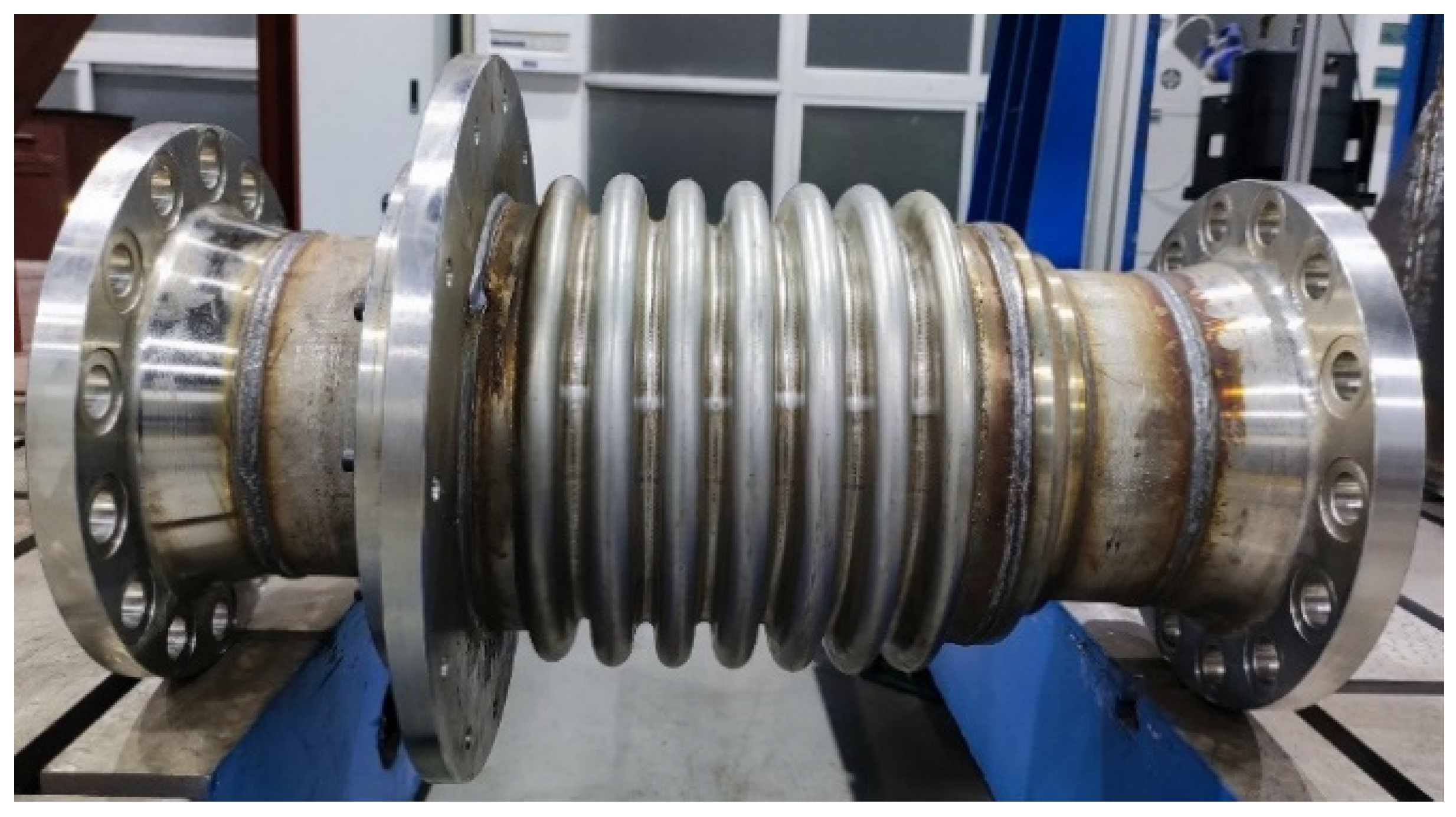
2. Design of Pipe Element Passing through Bulkhead with Symmetrical Elastic Installation

The three-dimensional design of the pipe element passing through the bulkhead with symmetrical elastic installation proposed in this paper is shown in Figure 1a, and the two-dimensional design is shown in Figure 1b. The pipe element passing through the bulkhead with symmetrical elastic installation is mainly composed of multi-layer thin-walled symmetrical metal bellows, conical tubes, an EMWM-filled damping member, connecting rings, end covers, end flanges, etc.
Unlike straight sleeves, a multi-layer thin-walled metal bellow is a symmetrical structure. The symmetrical metal bellows not only fits the installation of the ship’s pipeline, but also ensures the overall vibration reduction of the pipeline. It has better deformation compensation ability than the single-layer metal bellow of the same wall thickness and waveform, and the stress generated by the deformation is smaller. Therefore, this designed a multi-layer thin-walled symmetrical metal bellows as an elastic element. The corrugated thin-walled structure of the bellows was used to improve the flexibility of the pipe element passing through the bulkhead and provided a certain deformation compensation ability [33,34].
In order to improve the damping characteristics of the pipe element passing through the bulkhead, low-density EMWM components were used as damping elements, and the inner cavity of the metal bellows was filled with EMWM to improve the energy consumption capacity. Compared with rubber materials, EMWM can still maintain good vibration damping characteristics in extreme high temperature environments. Therefore, the rubber material is replaced by EMWM as the damping material of the pipe element passing through the bulkhead. All components of the pipe element passing through the bulkhead were connected by seam welding to achieve a reliable connection between the pipe element and the bulkhead. Because of contrasting the response characteristics of vibration transmitted from the pipe element passing through bulkhead with symmetrical elastic and rigid installation to the simulated bulkhead, the connection between the pipe element passing through the bulkhead and the bulkhead was connected by bolts.
Each component was processed in 304 stainless steel as raw material, and their material properties are shown in Table 1. The gap between the bellows and the pipe element was filled with low-density EMWM during the welding process. Finally, the residual stress of welding is eliminated by combining the hydraulic method with the vibration method. The prototype as finally prepared is shown in Figure 2.

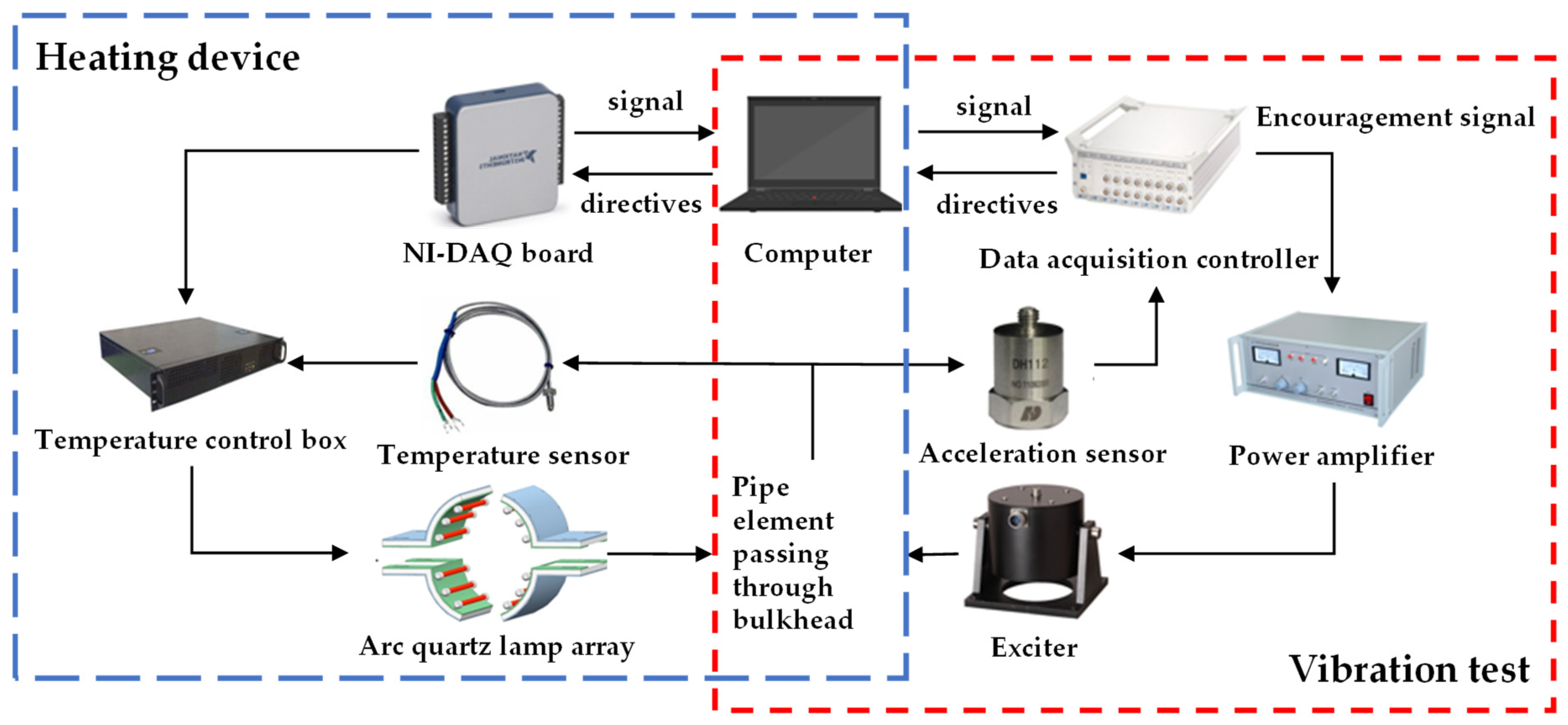
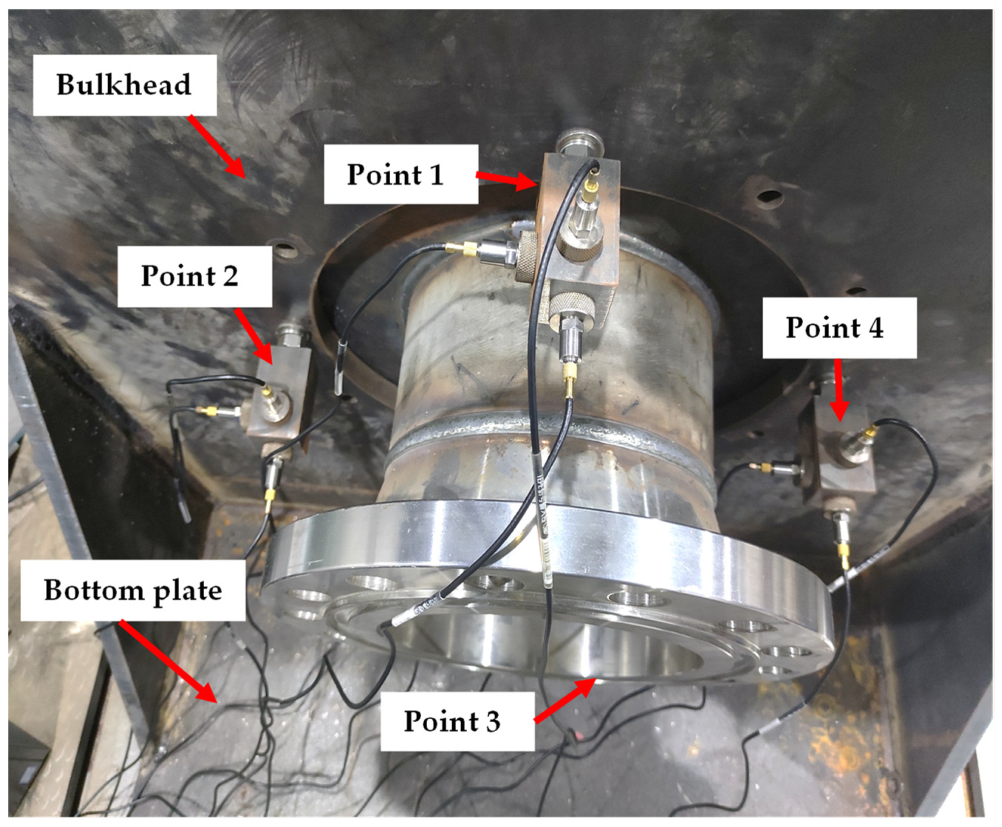
3. Test Bench and Study Description

Wu et al. [35] built a test system to test the pipe element passing through a bulkhead covered with EMWM. Therefore, drawing on their experience and methods, a thermal-vibration joint test frame was constructed. The principle of the thermal-vibration joint test frame is shown in Figure 3. The system was divided into a loading high temperature environment subsystem and vibration excitation acquisition subsystem. The loading high temperature environment subsystem consisted of an arc quartz lamp array, a temperature sensor, a temperature control box, an NI-DAQ board, a computer, etc. The operator configured the target temperature through the temperature control program, which was measured by the temperature sensor to compare the actual temperature with the target temperature. The NI-DAQ board was controlled by the temperature control program to transmit the quartz lamp array heating signal. When the power was amplified by the temperature control box, the arc quartz lamp array was heated until the pipe element passing through the bulkhead reached the target temperature.
The vibration excitation acquisition subsystem consisted of an electromagnetic exciter, ceramic excitation bar, acceleration sensor, data acquisition controller, computer, etc. The operator set the target excitation signal and monitored the data acquisition process through the supporting acquisition software. The control signal was outputted from the source channel of the data acquisition controller and the exciter was driven by the power amplifier to apply external excitation to the pipe element passing through the bulkhead. The vibration response signal was detected by the acceleration sensor and collected in real time by the input channel of the data acquisition controller. The loading high temperature environment subsystem and vibration excitation acquisition subsystem were independent and coordinated with each other so as to carry out dynamic mechanics performance tests of the pipe element passing through the bulkhead at different ambient temperatures. The physical diagram of the bench test is shown in Figure 4. Figure 5 shows the distribution of the four symmetrical measuring points on the bulkhead. Each measuring point was symmetrically distributed with the center of the pipe element. Each measuring point was equipped with three acceleration sensors for a total of 12 acceleration sensors in order to detect axial, radial and tangent direction vibration signals. The sensor was attached by the magnetic mount to the transfer block of the box. The detection method of symmetrically arranged sensors can represent the vibration response of the pipe element passing through the bulkhead when it is subjected to sinusoidal vibration. By comparing the vibration response, a good vibration damping level of the pipe element passing through the bulkhead with symmetrical elastic installation is obtained.
According to the test system, the following tests were carried out to verify the vibration damping performance of a pipe element passing through bulkhead with symmetrical elastic installation. Firstly, the harmonic response analysis of pipe element passing through the bulkhead was carried out. The mode superposition method was used as the calculation method to apply the same excitation load to the pipe element passing through the bulkhead with symmetrical elastic and rigid installation. By comparison experiments, the acceleration response of the same measuring point on the bulkhead was simulated. Through data processing, the vibration characteristics and vibration damping effects of both were analyzed. A fixed support was used on the four edges of the simulation bulkhead. Sine loads along the X-axis direction (radial direction) and Z-axis direction (axial direction) were applied on the left end flange face with a size of 200 N, a frequency range of 5 to 2000 Hz, a phase angle of 0 degrees, and a step of 2 Hz, respectively.
After that, in order to explore the effect of temperature on the pipe element passing through the bulkhead with symmetrical elastic installation, a temperature test was carried out. The sine sweep signal from 5 to 2000 Hz was fed into the exciter through the signal source channel of the dynamic data acquisition controller, while the position of the ceramic excitation bar and the gain of the power amplifier were adjusted. The above operation ensured that the pipe element passing through the bulkhead with symmetrical elastic and rigid installation had the same excitation load. Radial and axial excitation loads were applied, with ambient temperatures of RT (25 °C), 100 °C, 200 °C, and 300 °C, a sweep time of 200 s, and a sampling frequency of 4 kHz. Four symmetrical measuring points were collected, with a total of 12 acceleration response signals (Figure 5). The insertion loss of each measuring point was obtained by the same calculation method.
To evaluate the vibration damping performance of the pipe element passing through the bulkhead, the acceleration frequency response signal of the measuring point is numerically converted. The vibration acceleration level Z and insertion loss IL are calculated according to the following formula.
Z = 20 lg ( a ) + 120
I L = Z g + Z c
where a is the acceleration signal of the bulkhead measuring point; Z g is the vibration acceleration level of the pipe element passing through the bulkhead with rigid installation; and Z c is the vibration acceleration level of the pipe element passing through the bulkhead with symmetrical elastic installation.

4. Results and Discussion

4.1. Finite Element Modeling

The 3D model of the pipe element passing through the bulkhead was established by the 3D modeling software UG, and the finite element analysis was carried out through ANSYS Workbench. The mesh processing of the model is shown in Figure 6.
When the wave is transmitted in the air medium, it is mainly transmitted in the form of a longitudinal wave and a compression wave. In the solid medium, it is mainly transmitted by bending waves. In this case, 6 to 10 elements should be included in one bending wavelength [36]. The flexural wave velocity CB can be derived from the longitudinal wave velocity CL, and the relationship is as follows:
C B = 0.535 2 π f C L h
where: f—vibration frequency; h—medium thickness.
And the longitudinal wave velocity CL in a solid medium can be expressed as:
C L = E ρ ( 1 μ 2 )
where: E—the elastic modulus of the material; ρ—the density of the material; μ—the Poisson’s ratio of the material.
Substitute the material parameters given above into equation, considering that the plate thickness factor is discussed in the follow-up research. Here, a valley value of pipe thickness is set to 3 mm and substituted into the calculation. The relationship between flexural wave velocity and wavelength is as follows:
λ B = C B f
Therefore, the wavelength of the bending wave can be obtained as 0.086 m. According to a wavelength including six units, the unit size should be less than 0.014 m. Considering that some parts of the model may be rough during mesh division, which exceeds the specified limit, the above size is reduced, and the final selected element size is 5 mm. The pipe element and bulkhead of the model used hexahedral meshes. (Suppose X was the circumferential direction, Y was the radial direction, and Z was the axial direction).
Due to the complexity and random arrangement of the metal wires inside the EMWM, it was difficult to use the modeling method for a simulation. Therefore, simulations could only be performed with similar material features. EMWM materials were replaced by a Mooney-Rivlin model [37], as shown in Table 2. In the model, the upper, lower, left, and right surfaces of the bulkhead were fixed constraints, and the connection relationship of each component was bonded. A pressure of 2.5 MPa was applied inside the pipe element. The damping coefficient of 304 stainless steel is 0.001. Different loads/displacements were applied to the ends of the pipe element passing through the bulkhead according to the simulation conditions.

4.1.1. Intensity Analysis

The characteristics of the load such as axial and radial displacement compensation amplitude and acceleration shock of the structure were studied, and the strength of the structure was analyzed to meet the requirements and not be destroyed. The model was loaded with an axial displacement of 5 mm, a radial displacement of 3 mm, an axial and radial acceleration impact size of 10 g, and a pulse width of 16 ms. The model stress cloud diagram can be seen below.
The main failure mode of metal bellows is a fracture caused by cracks in the corrugation. As seen from the results of the strength simulation (Figure 7), the maximum stress of the designed model is 258.58 MPa, and does not exceed the strength limit of the material under displacement compensation and impact load. It was shown that the designed structure can maintain good mechanical properties under displacement compensation and impact load.

4.1.2. Modal Analysis

Modal analysis could study the vibration characteristics inherent in the structure and was also an important part of the dynamic analysis, so the modality of the model was calculated. The results of the former fourth-order modes are shown in Table 3.
The former third-order modes of the pipe element passing through the bulkhead with symmetrical elastic installation are the swing of the center pipe element in the direction of the X-axis and the Y-axis, and the stretching along the Z-axis, while the fourth-order mode is each deformation of the metal bellows. Because the model is symmetrical along the Z axis, the resonance frequency results of the first-order mode and second-order mode are not much different, and the vibration patterns are very similar. The other modes show that the deformation of the bellows itself is different. It can be seen from the analysis that due to the characteristics of its geometric structure, the bellows can deform through its own flexibility when subjected to vibration and resist the influence of vibration through the energy consumption of deformation. Due to the damping effect of EMWM, the vibration reduction effect is more obvious. Therefore, tests can be carried out to demonstrate its vibration reduction.

4.2. Harmonic Response Analysis of Different Direction of Excitation

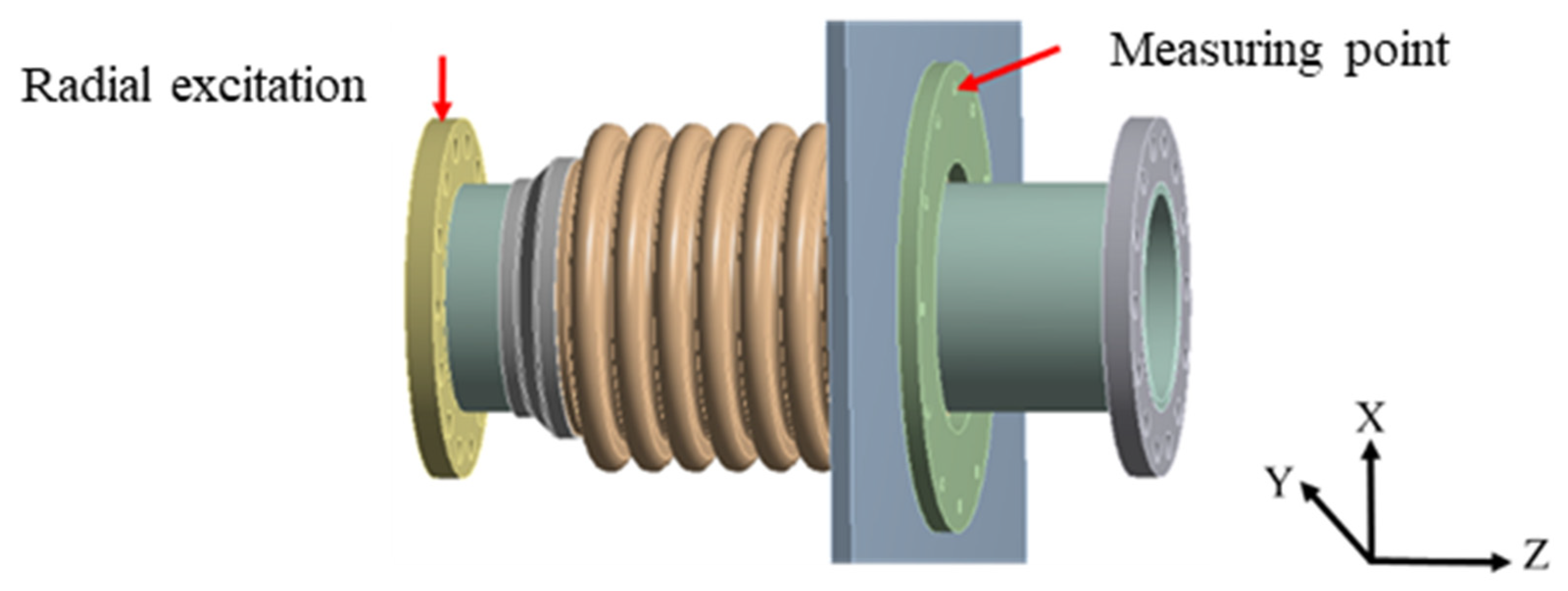
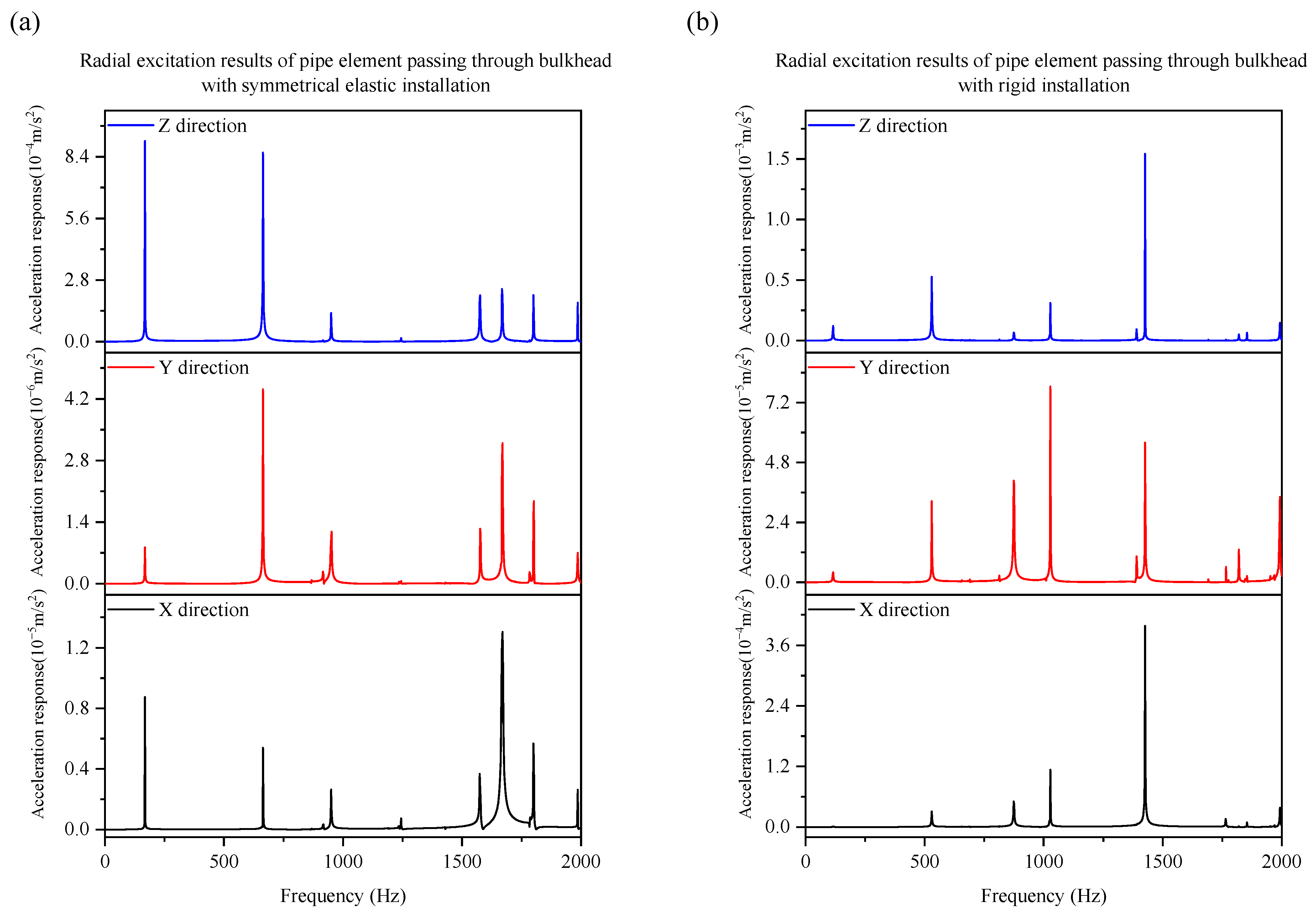
4.2.1. Harmonic Response Analysis during Radial Excitation

The excitation and measuring point positions when applying radial (X-directional) excitation loads to the pipe element passing through the bulkhead are shown in Figure 8. The acceleration responses in the same measuring point were detected in three directions.
The pipe element passing through the bulkhead with symmetrical elastic and rigid installation were applied to the same radial sine excitation. For the same measuring point, the acceleration frequency signals of each direction were compared and analyzed, as shown in Figure 9.
As seen from Figure 9, the inherent frequency of the pipe element passing through the bulkhead changes significantly after the use of the symmetrical elastic installation design. Through the test, the resonance frequencies of the pipe element passing through the bulkhead with symmetrical elastic installation can be obtained as 168 Hz, 663 Hz, 942 Hz and 1638 Hz. Compared with the simulation results, the error sizes are 4.5%, 9.0%, 3.8%, and 5.2%, respectively. Therefore, the simulation has a certain reliability. The number of resonant peaks decreases, and the vibration magnitude is greatly reduced. Since the metal bellows was subjected to a sinusoidal load, the corrugation underwent a deformation similar to a reciprocating motion with the occurrence of vibration. Through the deformation of the structure, the influence of the vibration was alleviated. In addition, due to the deformation of the bellows, the EMWM filled damping member was also deformed. The deformation of the EMWM led to the slippage and extrusion of the internal metal wire, and the dry friction force generated between the internal metal wire could dissipate the vibration energy. This was the energy dissipation mechanism of EMWM as a damping material.
Comparing the acceleration response of the three test directions, the response magnitude of Z direction is the largest, the X direction is second, and the Y direction is the smallest. The reason is that the Z direction is the axial direction of the pipe element, and the pipe can move freely in this direction. The X and Y directions are fixed ends, but the response values in the X direction are greater due to the fact that the X direction is in the same direction as the vibration direction.

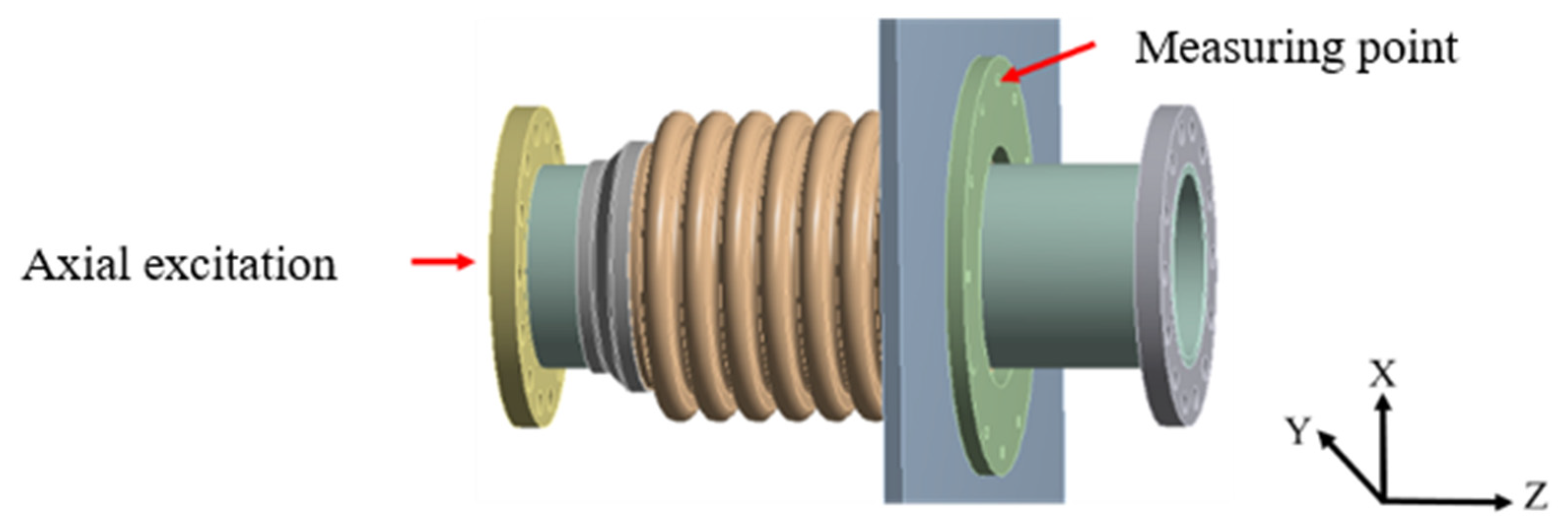
4.2.2. Harmonic Response Analysis during Axial Excitation

The excitation and measuring point positions when applying axial (Z-directional) excitation loads to the pipe element passing through the bulkhead are shown in Figure 10. The acceleration responses of the same measuring point as the axial excitation were collected in different directions.
The pipe element passing through the bulkhead with symmetrical elastic and rigid installation were applied to the same axial sine excitation. For the same measuring point, the acceleration frequency signal of each direction was compared and analyzed, as shown in Figure 11.
Similar to radial excitation loads, the inherent frequency of the pipe element passing through bulkhead changes significantly after the use of the symmetrical elastic installation design. The number of resonant peaks decreases, and the vibration magnitude is greatly reduced. This is also because of the structural flexibility of the metal bellows and the damping performance of the EMWM-filled damping member, which shows a good vibration damping and vibration isolation effect under the installation with elastic structure. Furthermore, the axial (Z-direction) load is also the most responsive in the Z magnitude for a pipe element passing through a bulkhead in which the symmetrical elastic installation is 10−4. Table 4 shows the calculation results of insertion loss in the harmonic response analysis. It can be seen from the table that the Y-direction has the largest insertion loss, with a value of 25.4 dB, followed by the X-direction and Z-direction. From the comparison, the result is consistent with the frequency response curve.

4.3. Vibration Damping Performance Analysis

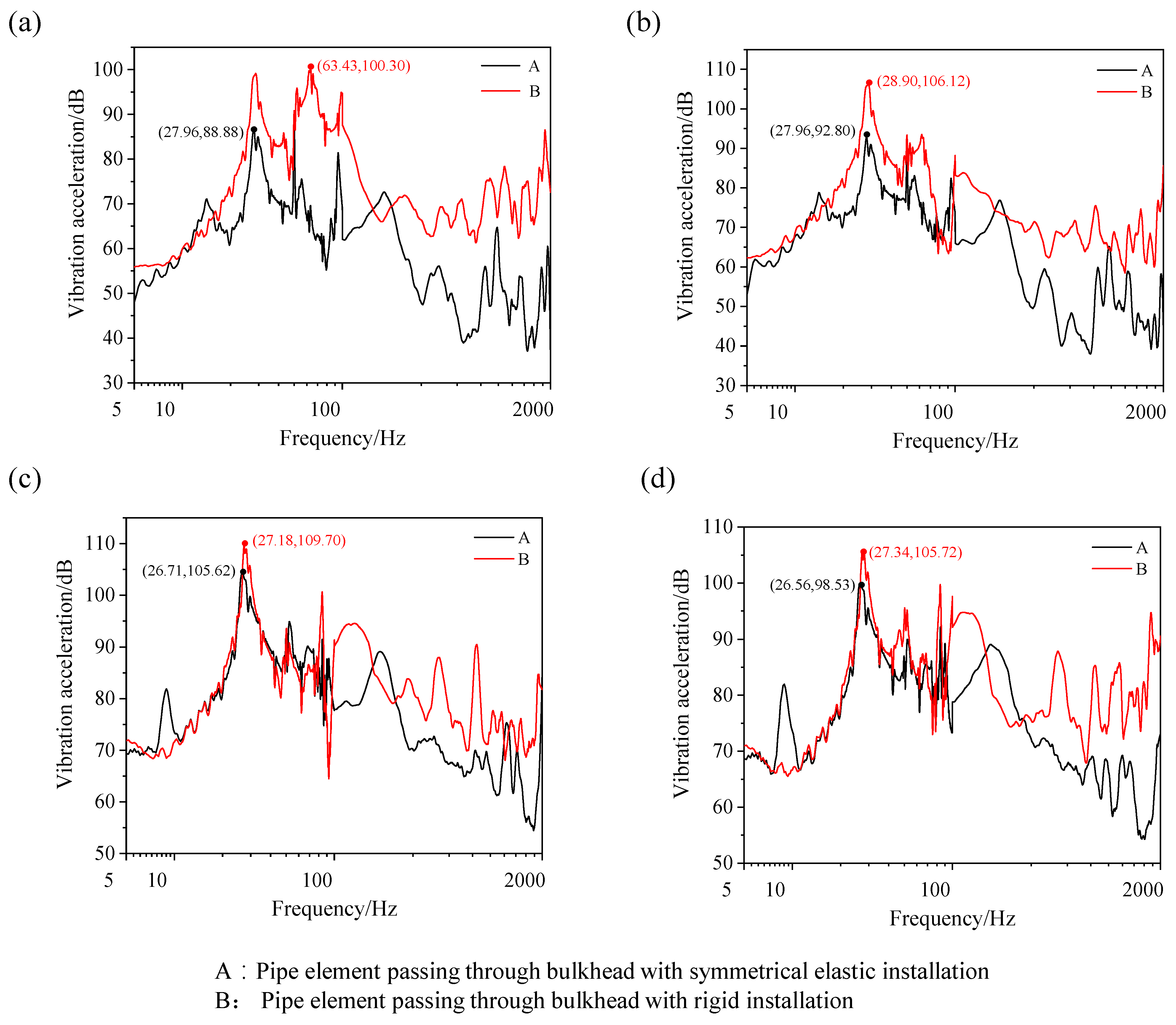
4.3.1. The Vibration Damping Performance of Pipe Element Passing through Bulkhead

In order to verify the vibration damping performance of pipe element passing through bulkhead with symmetrical elastic installation, the collected acceleration signal was processed by Equations (1) and (2), and the insertion loss corresponding to each symmetrical measuring point was obtained. At the same time, due to the need to examine the overall vibration damping performance of the design, the 12 measuring points were taken for average. Finally, when loading on radial and axial directions at different temperatures, the insertion loss of the pipe element passing through the bulkhead with symmetrical elastic installation was determined. The results are shown in Table 5 below. At RT (25 °C), 100 °C, 200 °C, 300 °C, the axial acceleration response signals of pipe element passing through bulkhead with symmetrical elastic and rigid installation of the point 1 are shown in Figure 12.
As seen from Table 5, a pipe element passing through the bulkhead with symmetrical elastic installation has good vibration damping performance in the full frequency band from 5 to 2000 Hz. The vibration damping performance under radial excitation load is better than that of the axial excitation load. At RT (25 °C) to 300 °C, the radial insertion loss is around 22 dB, while the axial insertion loss is between 12 and 15 dB. This shows that when loading the same size and frequency, the direction of vibration has a great effect on vibration response, with a difference of up to 10 dB. At high temperatures, the insertion loss of the pipe element passing through the bulkhead with symmetrical elastic installation does not change much when the radial excitation load is applied. The insertion loss under the axial load decreases slightly with the increase of temperature, but the reduction is small, with a maximum difference of only about 2.78 dB.
As seen from Figure 12, under different temperature environments and applying the same radial and axial excitation loads, there are significant differences between the natural frequency and the peak of the pipe element passing through the bulkhead with symmetrical elastic and rigid installation. In the low frequency range of 5 to 100 Hz, the difference is not large, and the number of resonant peaks is slightly increased due to structural changes in the pipe element passing through the bulkhead with symmetrical elastic installation. In the medium and high frequency band of 100 to 2000 Hz, the vibration acceleration level of the pipe element passing through bulkhead with rigid installation is very different from the symmetrical elastic installation, and the difference at some peaks can reach more than 30 dB.
Because a pipe element passing through a bulkhead with symmetrical elastic installation is designed to use multi-layer thin-walled metal bellows as an elastic element, its axial stiffness is greater than its radial stiffness. Therefore, under the same load, the axial deformation occurs less. When the pipe element is deformed under force, the EMWM filled damping member begins to dissipate energy. The greater the amount of deformation of the EMWM, the more dry frictions that occur between the metal wires in contact, and the greater vibration energy dissipated. Therefore, under the radial load, the vibration damping performance of the pipe element passing through a bulkhead with symmetrical elastic installation is better.

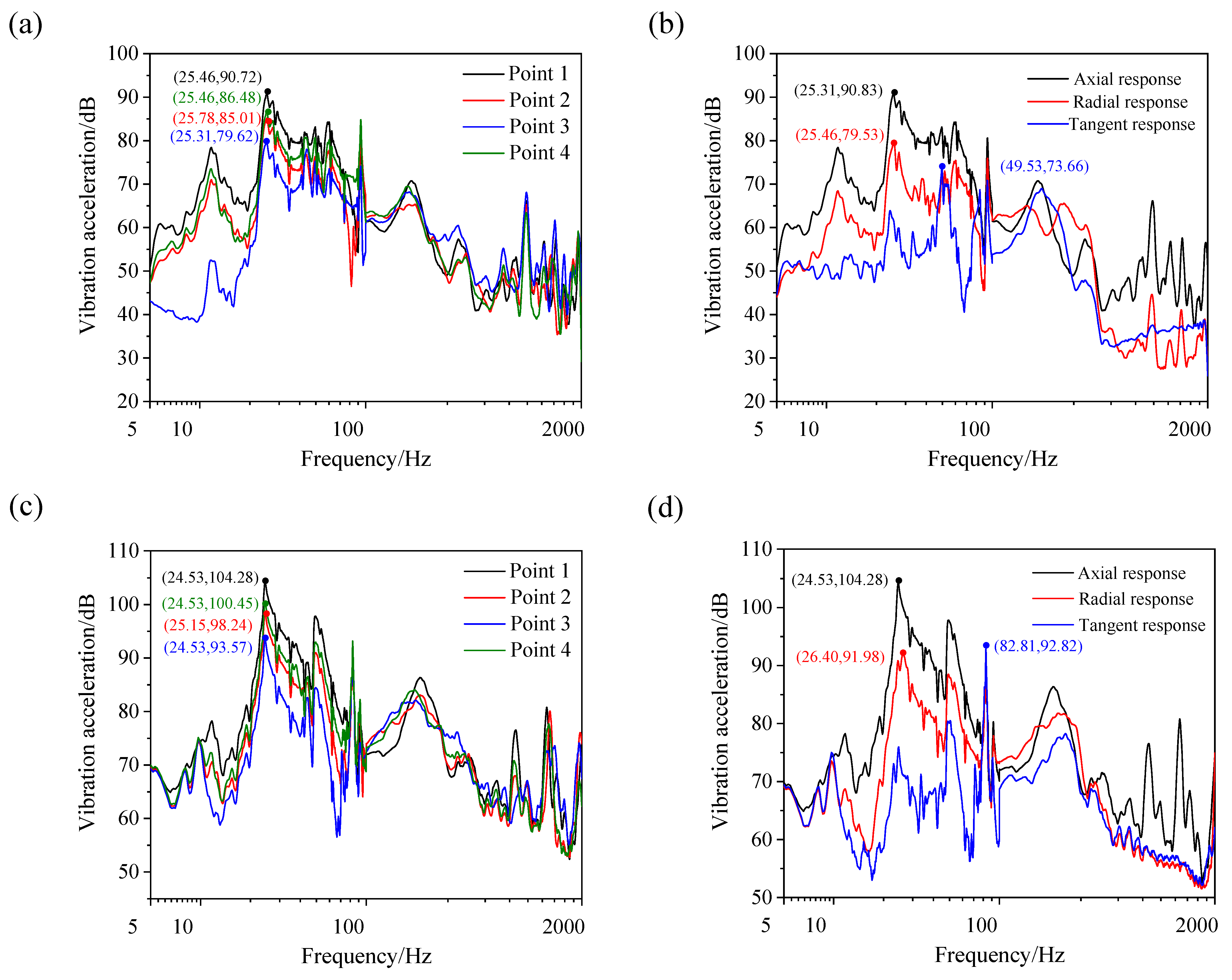
4.3.2. The Vibration Damping Performance of Different Symmetrical Measuring Points

At RT (25 °C), a pipe element passing through a bulkhead with symmetrical elastic and rigid installation was axially and radially excited. The vibration acceleration level Z of the two different symmetrical measuring points was calculated, and the insertion loss IL was calculated, as shown in Figure 13 and Table 6. The vibration response of different positions and directions of the simulation bulkhead was explored. Structural vibration characteristics were then obtained.
As seen from Figure 13, the vibration acceleration level of each measuring point changes with the change of the symmetrical measuring point and the direction of the test, both of which have a certain effect on the vibration response. Comparing the axial acceleration curves of different measuring points, no matter how the direction of excitation changes, in the low-frequency band, the vibration acceleration level of point 1 is greater than that of other measuring points, and the vibration acceleration level of point 3 is the smallest. However, in the high frequency band, the frequency composition is more complex and the difference is smaller. This is due to the fact that the simulation bulkhead structure is unilaterally fixed and that point 3 is near the fixed end, resulting in a smaller vibration amplitude. Point 1 is close to the free end and the excitation load position, so its vibration is most obvious. For acceleration signals in different directions of the same point, the acceleration response in the axial direction is large and the response in the tangential direction is minimal, regardless of the direction of the vibration source.
As seen from Table 6, under excitation loads in different directions, the insertion loss has a certain relationship with the position of symmetrical measuring points and the test direction. The insertion loss results of point 2 and point 4 are the greatest, and the difference between the other measures is about 5 to 7 dB. Because the positions of the two points are symmetrical on the simulation bulkhead, and are closer to the upper, left and right free end, the response trend is similar. In addition, the insertion loss results of two points are slightly larger than that of the other measuring points. For different test directions, the insertion loss is not much different, as the difference is around 3 dB. Therefore, the closer to the free end of the measuring point, the better the vibration reduction effect, and the designed structure in all directions has good vibration damping performance.

4.3.3. The Vibration Damping Performance of Different Temperature Environments

At RT (25 °C), 100 °C, 200 °C and 300 °C, a pipe element passing through a bulkhead with symmetrical elastic installation was radially and axially excited, respectively. According to the axial acceleration response of each symmetrical measuring point, its vibration acceleration level and insertion loss were obtained. Therefore, the vibration reduction performance of the pipe element passing through the bulkhead with symmetrical elastic installation was explored in different temperature environments.
As seen from Figure 14 and Figure 15, under the radial and axial excitation loads of the pipe element passing through the bulkhead with symmetrical elastic installation, the ambient temperature has little effect on the vibration acceleration level of each symmetrical measuring point. Although temperature has a slight effect on some frequency bands, it can still maintain good vibration damping performance.
Table 5 shows the average insertion loss of a pipe element bulkhead with symmetrical elastic installation at different temperatures. As seen from Table 5, when the radial load is applied, the insertion loss does not change much with the temperature, the maximum difference is only about 1 dB, and the change value is 4.35%. When the axial load is applied, the insertion loss decreases with the increase of temperature, and the maximum difference is about 2.7 dB, which is 18.5% reduced.
The coefficient of friction of wire increases with the temperature at RT (25 °C) to 200 °C. However, when the temperature is higher, a dense oxide film is formed on the surface of the wire, which reduces the friction coefficient. At the same time, the thermal expansion coefficient of EMWM increases with the temperature. The number of contact points and wires within the EMWM has increased rapidly, and the slippage, friction and extrusion between the turns becomes more obvious [38,39,40,41]. This leads to a certain increase in energy consumption. In general, the damping properties of EMWM are not sensitive to temperature changes. Therefore, the design structure has little change in vibration reduction performance, and works stably in high temperature environments.

5. Conclusions

In this paper, a new design of pipe element passing through a bulkhead with a symmetrical elastic installation was proposed for the vibration damping problem of a ship pipeline system. Through ANSYS, the strength of pipe element passing through the bulkhead with symmetrical elastic installation under different conditions was analyzed. The harmonic response analysis of the pipe element passing through the bulkhead with symmetrical elastic and rigid installation was carried out with the modal superposition method as the calculation direction. The accuracy of the overall model is verified, but the individual modeling of EMWM is still a big problem. At the same time, by comparing it with the vibration response of rigid installation, the vibration damping performance of a pipe element passing through a bulkhead with symmetrical elastic installation was verified. A series of comparison experiments were carried out to investigate the influence of temperature, symmetrical measuring points and exciting directions. Therefore, the vibration damping performance of a pipe element passing through bulkhead was verified. The study concluded that:
(1)
Compared with the rigid installation, after adding the EMWM materials, the overall vibration damping performance of the structure is obvious. The maximum average insertion loss of each direction is 25.4 dB. At the same time, the resonant frequency and resonance peak of a pipe element passing through a bulkhead with a symmetrical elastic installation is significantly reduced.
(2)
A pipe element passing through a bulkhead with symmetrical elastic installation has a better vibration isolation effect in the full frequency band of 5 to 2000 Hz. The maximum insertion loss is 23.4 dB. At different temperatures and different excitation directions, the insertion loss can reach more than 12 dB.
(3)
The excitation direction has a great influence on the vibration damping performance of a pipe element passing through a bulkhead with symmetrical elastic installation. The vibration damping performance under a radial load is better than that of the axial load, and the insertion loss difference can be up to about 10 dB.
(4)
The vibration characteristics of a pipe element passing through a bulkhead with symmetrical elastic installation are less affected by ambient temperature. It can maintain good vibration damping performance in a wide temperature range.

Author Contributions

Conceptualization and methodology, Y.W., Y.T., Z.Q. and H.B.; data curation, Y.T. and Z.Q.; validation, Y.W., Y.T. and Z.Q.; writing—original draft preparation, Y.T. and Z.Q.; writing—review and editing, Y.W., X.C. and H.B. All authors have read and agreed to the published version of the manuscript.

Funding

This research was supported by National Natural Science Foundation of China (Grant No. 12002088), Natural Science Foundation of Fujian Province (Grant No. 2020J05103), Education and scientific research foundation for young teachers in Fujian Province (Grant No. JAT190008) and Starting Grants of Fuzhou University (Grant No. GXRC-20017).

Institutional Review Board Statement

Not applicable.

Informed Consent Statement

Not applicable.

Data Availability Statement

Not applicable.

Conflicts of Interest

The authors declare that they have no conflicts of interest.

References

  1. Sotoodeh, K. A review on subsea process and valve technology. Mar. Syst. Ocean Technol. 2019, 14, 210–219. [Google Scholar] [CrossRef]
  2. Kim, T.Y.; Yoon, S.W.; Cho, J.H.; Kim, Y.H.; Kim, M.H. Vibration characteristics of filament wound composite tubes applied to the intermediate shaft in ship propulsion system. Mod. Phys. Lett. B 2019, 33, 1940029. [Google Scholar] [CrossRef]
  3. Wang, G.Z.; Liu, Y.H. Virtual design of monitoring and forecasting system of ship’s under water noise. Noise Vib. Control 2009, 29, 6–10. [Google Scholar]
  4. Matuszewski, L. Application of Shape Memory Alloys in Pipeline Couplings for Shipbuilding. Pol. Marit. Res. 2020, 27, 82–88. [Google Scholar] [CrossRef]
  5. Li, Z.; Tang, Y.; Tang, F.; Chen, Y.; Chen, G. Elastic buckling of thin-walled polyhedral pipe liners encased in a circular pipe under uniform external pressure. Thin Wall Struct. 2017, 123, 214–221. [Google Scholar] [CrossRef]
  6. Wang, J.; Shuai, Y.; Feng, C.; Zhang, P.; Wang, T.; Lin, N.; Liu, Z. Multi-dimensional mechanical response of multiple longitudinally aligned dents on pipelines and its effect on pipe integrity. Thin Wall Struct. 2021, 166, 108020. [Google Scholar] [CrossRef]
  7. Pratiwi, E.; Artana, K.B.; Dinariyana, A. Ship Collision Frequency during Pipeline Decommissioning Process on Surabaya West Access Channel (SWAC). J. Eng. Sci. Technol. 2019, 14, 2013–2033. [Google Scholar]
  8. Cheng, H.; Pinheiro, B.C.; Estefen, S.F.; Xu, L.; Paz, C.M.; Duan, M. Ultimate bending strength of sandwich pipes with actual interlayer behavior. Thin Wall Struct. 2021, 161, 107476. [Google Scholar] [CrossRef]
  9. Jiao, X. Heat-Solid Coupling Analysis of the Cooling Water Jacket of the Through-Cabin Fitting; Harbin University of Engineering: Harbin, China, 2013. [Google Scholar]
  10. Peng, Y.F.; He, H.Y.; Li, S.; Yu, J. Research on the vibration reduction mechanism of elastic pipe penetration piece and simulation. Ship Sci. Technol. 2011, 33, 119–122. [Google Scholar]
  11. Yin, X.Q.; Jin, X.; Liu, T.G. Analysis of technology property for pipe element passing through bulkhead with elasticity. Ship Eng. 2010, 1, 112–116. [Google Scholar]
  12. Pan, G.X.; Jing, H.S.; Liu, T.G. Experiment for influence to vibration isolation of deviation in mounting on pipe element passing through bulkhead with elasticity. Ship Sci. Technol. 2011, 33, 48–54. [Google Scholar]
  13. Jing, H.S.; Hu, Y.; Liu, T.G. Simulation analysis on vibration isolation of elastic pipe element passing through bulkhead with mounting deviation. Ship Ocean Eng. 2011, 40, 24–25. [Google Scholar]
  14. Hu, D.F.; Jin, X.; Liu, T.G.; Zhou, C.Q. Design of pipe element passing through bulkhead with elastic installation. Shipbuild. China 2011, 52, 146–153. [Google Scholar]
  15. Shen, Z.F.; Wu, S.M.; Zhang, Y.; Zhou, Z.J. Research and design of pipe penetration piece with damping based on FEM. Ship Sci. Technol. 2013, 35, 73–77. [Google Scholar]
  16. Li, G.L. The Cooling and Vibration Attenuation Design of the High Temperature and High Pressure Pipe Penetration Piece; Harbin University of Engineering: Harbin, China, 2012. [Google Scholar]
  17. Qiu, D.L. Dynamic Analysis of the Ship Pipes System; Harbin University of Engineering: Harbin, China, 2013. [Google Scholar]
  18. Xiong, J.Y. The Design and Test Study of Elastic Wearing Compartment Vibration Device; Huazhong University of Science and Technology: Wuhan, China, 2019. [Google Scholar]
  19. Chen, G.F.; Li, W.; Wang, B.; Li, P. Research on vibration isolation and sealing technology for flexible piping penetration. Ship Sci. Technol. 2020, 42, 68–70. [Google Scholar]
  20. Li, J.W. Research on Periodic Active Constraint Layer Damping Treatment of Pipeline System; Dalian University of Technology: Dalian, China, 2020. [Google Scholar]
  21. Chapnik, B.; Currie, I.G. Noise reduction using finite-length flexible segments. J. Vib. Acoust. 2000, 122, 94–108. [Google Scholar] [CrossRef]
  22. Wang, Q.; Hu, M.; Yao, B.Y. Study on vibration depression of pipeline of marine reciprocating pump. Ship Eng. 2002, 1, 27–31. [Google Scholar]
  23. Chiu, M.C. Numerical assessment for a broadband and tuned noise using hybrid mufflers and a simulated annealing method. J. Sound Vib. 2013, 332, 2923–2940. [Google Scholar] [CrossRef]
  24. Oh, S.; Wang, S.; Cho, S. Development of Energy Efficiency Design Map based on acoustic resonance frequency of suction muffler in compressor. Appl. Energy 2015, 150, 233–244. [Google Scholar] [CrossRef]
  25. Wu, Y.W.; Li, S.Z.; Bai, H.B.; Jiang, L.; Cheng, H. Experimental and constitutive model on dynamic compressive mechanical properties of entangled metallic wire material under low-velocity impact. Materials 2020, 13, 1396. [Google Scholar] [CrossRef] [Green Version]
  26. Al-Khateeb, E.M.; Vance, J.M. Experimental Evaluation of a Metal Mesh Bearing Damper in Parallel with a Structural Support. In Proceedings of the Asme Turbo Expo: Power for Land, Sea, & Air, New Orleans, LA, USA, 4–7 June 2001. [Google Scholar]
  27. Chandrasekhar, K.; Rongong, J.A.; Cross, E. Frequency and amplitude dependent behaviour of tangled metal wire dampers. In Proceedings of the International Conference on Noise and Vibration Engineering (ISMA), Leuven, Belgium, 15–17 September 2014; pp. 559–572. [Google Scholar]
  28. Ponomarev, Y.K. On transformation of hysteresis in damper rings made of “metal rubber” pressure-tested wire material under precessional loading conditions. J. Eng. Appl. Sci. 2014, 9, 1866–1872. [Google Scholar]
  29. Jiang, F.; Ding, Z.Y.; Wu, Y.W.; Bai, H.B.; Zi, B. Energy dissipation characteristics and parameter identification of symmetrically coated damping structure of pipelines under different temperature environment. Symmetry 2020, 12, 1283. [Google Scholar] [CrossRef]
  30. Xiao, K.; Bai, H.; Xue, X.; Wu, Y. Damping characteristics of metal rubber in the pipeline coating system. Shock Vib. 2018, 2018, 1–11. [Google Scholar] [CrossRef] [Green Version]
  31. Chandrasekhar, K.; Rongong, J.; Cross, E. Mechanical behaviour of tangled metal wire devices. Mech. Syst. Signal Process. 2019, 118, 13–29. [Google Scholar] [CrossRef] [Green Version]
  32. Zhu, W.W.; Xing, L.X.; Ren, Z.Y.; Bai, H.B.; Zhang, Y.J.; Zheng, X.Y. Vibration damping performance of non-forming metal rubber shock absorber. J. Fuzhou Univ. Nat. Sci. Ed. 2020, 48, 747–754. [Google Scholar]
  33. Radhakrishna, M.; Kameswara Rao, C. Axial vibrations of U-shaped bellows with elastically restrained end conditions. Thin Wall Struct. 2004, 42, 415–426. [Google Scholar] [CrossRef]
  34. Jahromi, A.G.; Hatami, H. Energy absorption performance on multilayer expanded metal tubes under axial impact. Thin Wall Struct. 2017, 116, 1–11. [Google Scholar] [CrossRef]
  35. Wu, K.; Bai, H.; Xue, X.; Li, T.; Li, M. Energy Dissipation Characteristics and Dynamic Modeling of the Coated Damping Structure for Metal Rubber of Bellows. Met. Open Access Metall. J. 2018, 8, 562. [Google Scholar] [CrossRef] [Green Version]
  36. Ihlenburg, F.; Babuska, I. Finite-element solution of the helmholtz-equation with high wave-number 1. The h-version of the fem. Comput. Math. Appl. 1995, 30, 9–37. [Google Scholar] [CrossRef] [Green Version]
  37. Ma, C.B. Study on the Shearing and Vibrational Mechanics of Metal Rubber; Harbin University of Engineering: Harbin, China, 2016. [Google Scholar]
  38. Ding, Z.; Bai, H.; Wu, Y.; Ren, Z.; Shao, Y. A Constitutive Model of Plate-Like Entangled Metallic Wire Material in Wide Temperature Range. Materials 2019, 12, 2538. [Google Scholar] [CrossRef] [Green Version]
  39. Zi, B.; Jiang, F.; Wu, Y.; Bai, H.; Tang, Y.; Lu, C. Analysis and Experimental Research on Vibration Reduction in Ship High-Temperature Pipeline Based on Long Coated Damping Structure. J. Mar. Sci. Eng. 2021, 8, 838. [Google Scholar] [CrossRef]
  40. Wu, Y.; Cheng, H.; Bai, H.; Li, S.; Tang, Y. Experimental investigation on static and dynamic energy dissipation characteristics of composite sandwich structure with entangled metallic wire materials and disc springs. Mater. Res. Express 2021, 8, 106507. [Google Scholar] [CrossRef]
  41. Zhu, Y.; Wu, Y.; Bai, H.; Ding, Z.; Shao, Y.; Sopanen, J. Research on Vibration Reduction Design of Foundation with Entangled Metallic Wire Material under High Temperature. Shock Vib. 2019, 2019, 7297392. [Google Scholar] [CrossRef]
Figure 1. Design of pipe element passing through a bulkhead with symmetrical elastic installation: (a) Three-dimensional map, (b) Two-dimensional map.
Symmetry 14 00453 g001
Figure 2. Prepare the finished prototype.
Symmetry 14 00453 g002
Figure 3. A diagram of a thermal-vibration joint test system.
Symmetry 14 00453 g003
Figure 4. Physical diagram of the test device.
Symmetry 14 00453 g004
Figure 5. Vibration response symmetrical measuring point.
Symmetry 14 00453 g005
Figure 6. Model meshing diagram: (a) Pipe element passing through bulkhead with symmetrical elastic installation, (b) Pipe element passing through bulkhead with rigid installation.
Symmetry 14 00453 g006
Figure 7. Structural strength stress cloud diagram: (a) Axial displacement 5 mm stress cloud diagram, (b) Radial displacement 3 mm stress cloud diagram, (c) Axial impact stress cloud diagram, (d) Radial impact stress cloud diagram.
Symmetry 14 00453 g007
Figure 8. Radial excitation and measuring point position.
Symmetry 14 00453 g008
Figure 9. Acceleration amplitude response curve by radial excitation: (a) pipe element passing through bulkhead with symmetrical elastic installation, (b) pipe element passing through bulkhead with rigid installation.
Symmetry 14 00453 g009
Figure 10. Axial excitation and measuring point position.
Symmetry 14 00453 g010
Figure 11. Acceleration amplitude response curve by axial excitation: (a) Pipe element passing through bulkhead with symmetrical elastic installation, (b) Pipe element passing through bulkhead with rigid installation.
Symmetry 14 00453 g011
Figure 12. Vibration acceleration response: under radial excitation (a) At RT (25 °C), (b) At 300 °C; under axial excitation (c) At RT (25 °C), (d) At 300 °C.
Symmetry 14 00453 g012
Figure 13. Vibration acceleration response: under radial excitation (a) Different axial responses of measuring points, (b) Different test directions; under axial excitation: (c) Different axial responses of measuring points, (d) Different test directions.
Symmetry 14 00453 g013
Figure 14. Vibration acceleration response under radial excitation: (a) Point 1, (b) Point 2, (c) Point 3, (d) Point 4.
Symmetry 14 00453 g014
Figure 15. Vibration acceleration response under axial excitation: (a) Point 1, (b) Point 2, (c) Point 3, (d) Point 4.
Symmetry 14 00453 g015
Table 1. Material parameter table.
MaterialElastic Modulus/PaPoisson’s RatioDensity kg/m3
304 stainless steel2.04 × 10110.2857.93 × 103
Table 2. EMWM material parameters.
C10C01D1
0.110.130.37
Table 3. Modal Analysis Results.
Mode1234
Frequency/Hz160.4723.2905.71723.6
Table 4. Insertion loss results in harmonic response analysis.
Excitation DirectionX-Direction ResponseY-Direction ResponseZ-Direction Response
Axial direction18.4 dB19.3 dB16.5 dB
Radial direction17.0 dB25.4 dB14.0 dB
Table 5. Insertion loss results.
DirectionRT (25 °C)100 °C200 °C300 °C
Radial direction23.023.422.522.4
Axial direction15.714.113.812.9
Table 6. Insertion losses for different points (unit dB).
DirectionPoint 1 AxialPoint 2 AxialPoint 3 AxialPoint 4 AxialPoint 1 RadialPoint 1 Tangent
Radial direction20.723.421.228.022.623.1
Axial direction15.118.315.220.719.015.7
Publisher’s Note: MDPI stays neutral with regard to jurisdictional claims in published maps and institutional affiliations.

