Article

A Novel Anti-Saturation Model-Free Adaptive Control Algorithm and Its Application in the Electric Vehicle Braking Energy Recovery System

1
School of Electrical and Control Engineering, North China University of Technology, Beijing 100144, China
2
School of Automation, Qingdao University, Qinhuangdao 266071, China
*
Author to whom correspondence should be addressed.
Symmetry 2022, 14(3), 580; https://doi.org/10.3390/sym14030580
Submission received: 19 February 2022 / Revised: 11 March 2022 / Accepted: 13 March 2022 / Published: 15 March 2022
(This article belongs to the Section Computer)

Abstract

:
In this work, a novel anti-saturation model-free adaptive control (AS-MFAC) algorithm is proposed for the problem of pure electric vehicle’s braking energy recovery with the uncertain dynamic external factors. In the process of energy recovery during vehicle braking, actuator saturation and error accumulation occur due to various external conditions. In AS-MFAC, the non-linear dynamics of the vehicle braking energy recovery process is firstly linearized via a novel dynamical linearization technique with a time-varying parameter pseudo partial derivative (PPD). Then, by proposing the concept of the saturation parameter, the AS-MFAC controller is designed. Consequently, the stability and safety of the braking system are guaranteed while ensuring energy recovery. The major advantages of the AS-MFAC algorithm are that the controller uses only input and output data from the regenerative braking control system and this approach addresses the actuator saturation problem as well as provides a feasible solution. Moreover, the stability of the AS-MFAC algorithm is proven by rigorous mathematical theory and its effectiveness is verified by a series of experimental simulations. Remarkably, the proposed AS-MFAC controller has the property of symmetry since the controller structure and the corresponding parameter (time-varying PPD) estimator are both inferred based on the project algorithm. Consequently, the structures of the controller and the parameters of AS-MFAC have a symmetric similarity.

1. Introduction

In the current situation of limited battery energy, there is a large gap between the driving range of pure electric vehicles (PEVs) and traditional internal combustion engine vehicles [1,2,3]. Energy consumption analyses of vehicles and improving the utilization rate of energy are important to improve the driving range of PEV [4]. Studies have shown that in urban driving conditions, from 30% to 50% of driving energy is consumed by the braking process, thus the recycling of braking energy is key to improving the driving range of PEV [5,6,7]. Research on the control of braking energy is necessary to be studied.
Braking energy recovery means that in the deceleration or braking process of an electric vehicle, by using assistant braking, which is added by the electric motor, some kinetic energy during braking can be regenerated into the battery to improve the energy utilization efficiency and endurance of the vehicle [8,9]. At present, most of the braking energy recovery systems in PEV combine hydraulic breaking and motor braking [10]. In recent years, this composite braking control strategy has gradually become the object of research on braking energy recovery and the subject of development by major automobile enterprises, such as General Motors in the United States [11] and both Nissan and Toyota in Japan [12,13]. The distribution strategy of the braking system is very important for energy feedback efficiency because only the driving wheels of a pure electric vehicle can recover energy [14]. How to reasonably distribute the braking torque and recover the braking energy as much as possible on the basis of ensuring vehicle braking safety and effectiveness has been always the most critical problem of regenerative braking systems [15,16,17]. Therefore, the essence of this research study is on braking energy recovery, focusing on controlling the reasonable distribution of the braking force.
For the problem of braking energy recovery, some model-based control methods can be applied [18,19,20]. In recent years, through the research of many scholars, the braking energy recovery technology of EVs has been continuously improved and developed. Focusing on the distribution control of braking energy recovery, Reference [21] proposed a predictive control strategy of braking energy recovery based on an improved genetic algorithm to ensure the balance and optimization of vehicle stability and economy. Reference [22] took the position of the brake pedal and the value of the state of charge (SOC) of the battery as input as well as the proportion of the motor braking force in the total braking force as the output to more accurately control the distribution of braking force according to the driving state. Reference [23] proposed a non-linear model of a predictive controller for a regenerative braking system that improved regenerative energy by distributing front and rear braking force moments. Reference [24], combined with the neural network algorithm, proposed a braking torque control strategy based on the neural network algorithm. Reference [25] comprehensively considered the braking feeling, braking energy recovery, and braking stability, and used a particle swarm optimization algorithm to optimize the distribution of the proportion of braking torque.
However, the above research did not consider the vehicle as a complex non-linear system with many model variables that operate under changing parameters and conditions. It is obviously not feasible to establish an accurate dynamic model of a vehicle and then design a control system.
Aiming at the above problems, in order to solve the problems caused by inaccurate dynamic modeling of the vehicle regenerative braking system, a data-driven control method is introduced in this paper. Since the 1990s, a variety of data-driven control methods emerged in academia, such as the synchronous perturbation random approximation algorithm [26], model-free adaptive control method (MFAC) algorithm [27], unfalsified control algorithm [28], iterative feedback tuning algorithm [29], virtual reference feedback tuning algorithm [30], and iterative learning control algorithm [31]. Among them, the MFAC algorithm, a typical data-driven control algorithm, has the advantage of requiring a small amount of calculation and having strong adaptability [32]; it has strong robustness and a good control effect for non-linear systems. MFAC has been successfully applied in many practical applications, such as autonomous car control [33], chemical industry [34], robot manipulator control [35], the injection molding process [36], etc. Therefore, focusing on the problem of vehicle regenerative braking, this paper will take MFAC as the main method.
In actual driving, due to the particularity of compound braking and other unpredictable external conditions (entering wading sections, bad road conditions, etc.), the vehicle braking force distribution strategy cannot achieve the goal quickly [37,38,39], which leads to large error accumulation in the vehicle braking process of the MFAC algorithm, relying on output data. Accumulated errors cause actuator saturation, which leads to large overshoots and affects the vehicle control. At present, there is little research on the anti-saturation of MFAC. Therefore, it is of great practical significance to study the MFAC method when the actuator is saturated.
The contribution of this paper is to propose an anti-saturation model-free adaptive control (AS-MFAC) algorithm to realize the control of the regenerative braking system. In the AS-MFAC algorithm, the non-linear dynamics of the vehicle braking energy recovery process are first linearized via a novel dynamical linearization technique with a time-varying parameter pseudo partial derivative (PPD). Then, the AS-MFAC controller is designed via a proposed concept for the saturation parameter. This scheme uses only (input and output) I/O data during vehicle operation and does not contain information about the vehicle model. Thus, it has strong portability for use in different vehicles. The main difference between the AS-MFAC and prototype MFAC method is that when establishing and solving the corresponding optimization problem, the actuator saturation caused by error accumulation is considered and the anti-saturation problem is dealt with in the algorithm. The stability of the method is mathematically proven and a semi-physical simulation proves the effectiveness of the proposed method.
The rest of this paper is organized as follows. In Section 2, the braking force distribution strategy of the driving and driven wheels during longitudinal braking of electric vehicles is studied. Section 3 introduces the AS-MFAC regenerative braking control strategy. Section 4 describes the results of simulations of the regenerative braking control strategy of the AS-MFAC algorithm. Section 5 summarizes the main conclusions of this paper and discusses future work.

2. Design of Braking Energy Optimization Controller and Dynamic Analysis of Braking Process

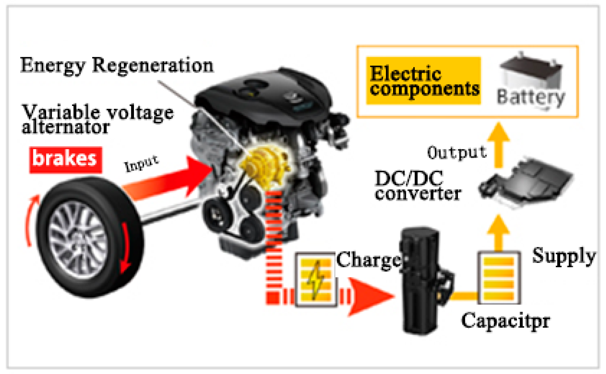
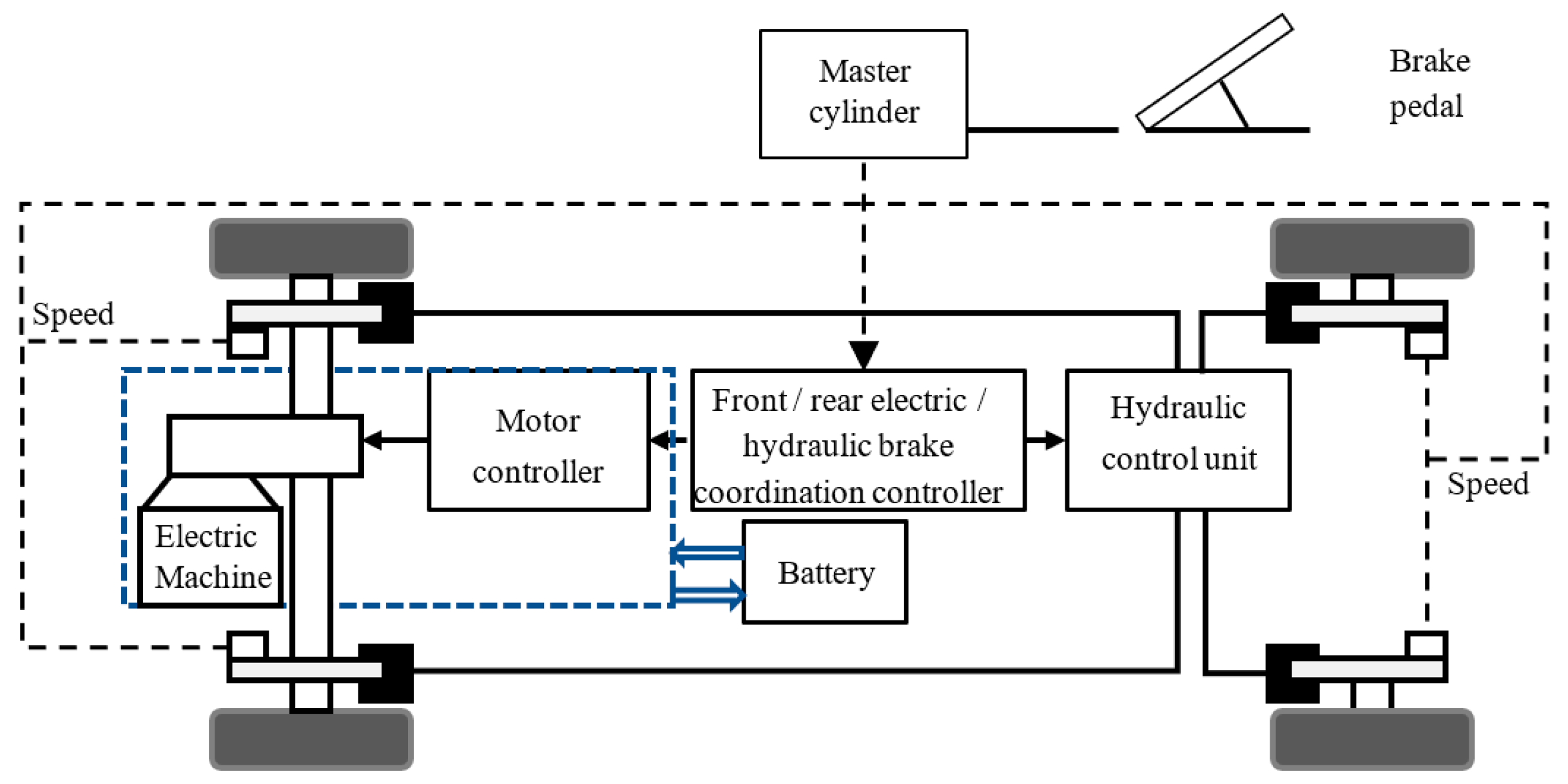
2.1. Dynamics Description of Regenerative Braking System

Braking energy recovery means that when the electric vehicle executes a deceleration or stop command, the motor braking is used to recover the braking energy and return this part of the energy to the energy storage device [40]. At this time, the motor is used as a generator [41]. When the electric vehicle is driven next time, the battery can drive the motor with the recovered energy to generate driving torque. At this time, the motor is used as an engine [42]. Figure 1 shows a braking energy recovery system for an electric vehicle.
Figure 2 shows the basic control principle of the braking energy recovery system. The braking controller determines the front and rear axle braking forces according to the braking demand, vehicle speed, and other signals, and then distributes the motor braking force and mechanical braking force. The specific control strategy is embedded in the front/rear electric/hydraulic braking coordination controller [43]. After the distribution of forces, the brake controller sends a control signal to the motor control unit and hydraulic control unit. In general, only the rear wheels (driving wheels) of the double drive pure electric bus can recover energy [44]. The greater the braking force allocated to the rear wheels, the higher the braking energy recovery efficiency of the whole vehicle. However, if too much braking force is distributed to the rear wheels, then the rear wheels lock before the front wheels and the rear wheels sideslip (i.e., lateral sliding), which makes the vehicle rotate uncontrollably [45,46]. Only when the front and rear wheels lock at the same time can the vehicle be in a stable state and make full use of the longitudinal adhesion coefficient [47]. How to distribute more braking force to the rear wheels and ensure the braking stability of the whole vehicle are key research points in this subject area.

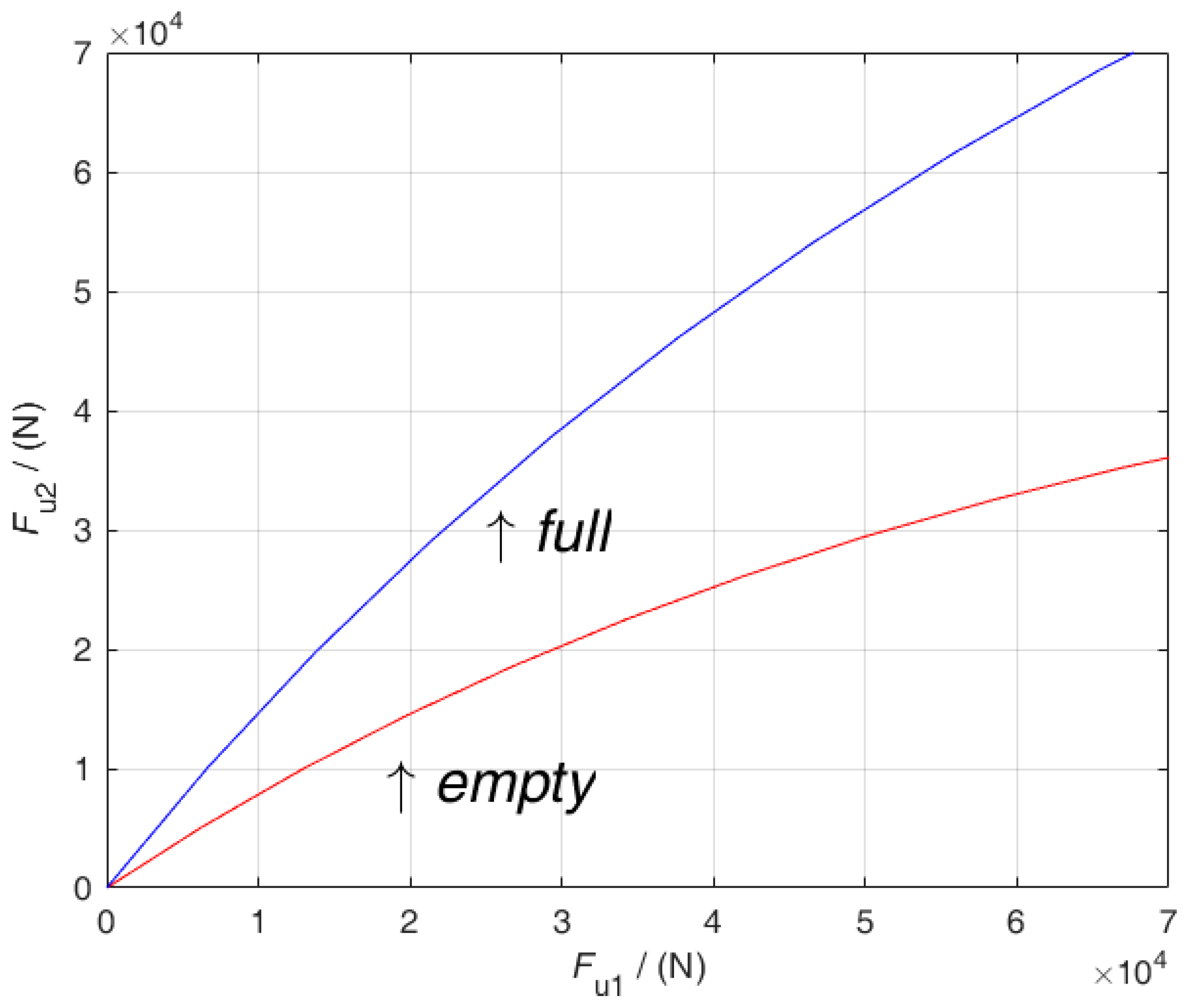
2.2. Forces during Braking and Braking Force Distribution

Before analyzing the braking force distribution ratio of the front and rear brakes, the forces during braking must be understood. Taking the BAIC BJ6123EVCA-52 pure electric city bus as an example, Figure 3 shows the stress analysis diagram during its operation.
As shown in the figure above, the torque for the rear wheel grounding point is
W 1 L = G b + m d v d t h
where:
  • W 1 represents the normal reaction force of the ground facing the front wheel (N);
  • G represents the force of gravity on the vehicle (N);
  • b represents the distance from the vehicle centroid to the centerline of the rear axle (mm);
  • m is the vehicle mass (kg);
  • h is the height of the vehicle centroid (mm); and
  • dv/dt indicates the deceleration of the vehicle ( m / s 2 ).
In taking the torque for the front wheel grounding point, we obtain
W 2 L = G a m d v d t h
where:
  • W 2 represents the normal reaction force of the ground facing the rear wheel (N) and
  • a represents the distance from the vehicle centroid to the centerline of the front axle (mm).
Then, the ground normal reaction force can be obtained as
{ W 1 = G L ( b + h g d v d t ) W 2 = G L ( a h g d v d t )
where:
  • g represents the acceleration of gravity.
If the front and rear wheels lock (successively or simultaneously) under the adhesion coefficient γ , then the total braking force of vehicle F = γ G , d v / d t = γ g , and the following equations can be obtained.
{ W 1 = G L ( b + γ h ) W 2 = G L ( a γ h )
where:
  • γ represents the road adhesion coefficient.
On the road surface with any adhesion coefficient γ , the condition of simultaneous locking of the front and rear wheels is that the sum of the braking forces of the front and rear wheels is equal to the adhesion, and the braking forces of the front and rear brakes are equal to their respective adhesion, that is:
{ F μ 1 + F μ 2 = γ G F μ 1 = γ W 1 F μ 2 = γ W 2
or
{ F μ 1 + F μ 2 = γ G F μ 1 F μ 2 = W 1 W 2
where:
  • F μ 1 represents the braking force of the front wheel brake and
  • F μ 2 represents the braking force of the rear wheel brake.
Substituting Equation (4) into Equation (6) yields:
{ F μ 1 + F μ 2 = γ G F μ 1 F μ 2 = b + γ h a γ h
Eliminating the variable γ obtains:
F μ 2 = 1 2 [ G h b 2 + 4 h L G F μ 1 ( G h + 2 F μ 1 ) ]
In Equation (8), the change in the weight of the vehicle G has the greatest impact on braking and G can be measured by the vehicle’s own sensor. Other parameters such as L, b, and h can be regarded as constants. Therefore, Equation (8) can be described by the following non-linear discrete time dynamic system:
F μ 2 ( k + 1 ) = f ( F ( k ) , F ( k 1 ) , F ( k n F ) , F μ 2 ( k ) , F μ 2 ( k 1 ) , , F μ 2 ( k n F μ 2 ) )
where F ( k ) and F μ 2 ( k ) represent the total braking torque and rear wheel braking torque at time k, respectively; n F and n F μ 2 are two unknown positive integers; and f ( ) : R n F + n F μ 2 + 2 R is an unknown non-linear function.
According to Equation (8), a curve can be drawn, that is, the relationship curve between the braking force of the front and rear brakes when the front and rear wheels are locked at the same time: the ideal braking force distribution curve of the front and rear brakes, referred to as line I for short [25]. Line I is a kind of complex non-linear function that is closely related to the center of gravity and weight of the vehicle, as well as to other parameters. According to the technical parameters of the vehicle in Table 1, Figure 4 shows line I of the vehicle under no-load and fully loaded conditions.
In Figure 4, the longitudinal and traverse axes represent the braking torques of the rear and front axles of the vehicle, respectively. If the braking force distribution curve is above line I, the unstable working condition of locking the rear wheel first will occur; if the braking force distribution curve is below line I, the recovery efficiency of the vehicle cannot be guaranteed. Only when the braking forces of the front and rear axles of the vehicle correspond to line I can the vehicle brake efficiently and work safely, and maximize energy recovery efficiency. Therefore, in the actual operation of the vehicle, it is very helpful to ensure that the braking force distribution curve of the vehicle is as close as possible to line I.
Based on line I, a new parallel braking distribution strategy with a high energy recovery rate is established under the actual operating conditions of vehicles by setting the total braking torque required by the vehicle as the input and the braking torque distributed to the rear wheels as the output. Due to the particularity of compound braking, the control based on system input and output data has a certain error accumulation that results in actuator saturation; this must be considered in the design of the control algorithm.

3. Design of the AS-MFAC Controller

In this section, the AS-MFAC algorithm based on the compact format dynamic linearization (CFDL) data model is used to solve the control problem of the regenerative braking system. The required total braking torque F ( k ) is the input and the braking torque to be distributed to the rear wheel F μ 2 is the output. The regenerative braking control system is a single-input single-output (SISO) discrete non-linear system and the general form of the CFDL of the SISO non-linear system is introduced in the following section.

3.1. Dynamic Linearization

Based on the above analysis, for the convenience of description, a general SISO non-linear discrete-time dynamic system is transformed from Equation (9) to Equation (10), which is used to describe the dynamic process of total braking force and rear axle braking force in braking force distribution engineering, as follows:
y ( k + 1 ) = f ( y ( k ) , , y ( k n y ) , u ( k ) , , u ( k n u ) )
where y ( k ) R and u ( k ) R represent the control output and input of the system at time k, respectively; n y and n u are two unknown positive integers; and f ( ) : R n u + n y + 2 R is an unknown non-linear function.
To establish the CFDL data model and use the AS-MFAC strategy, the following assumptions are introduced.
Assumption 1.
Except for the finite time point, the partial derivative of  f ( ) with respect to the  ( n y + 2 ) variable is continuous.
Assumption 2.
Except for finite time points, Equation (10) satisfies the generalized Lipschitz, that is, y ( k 1 + 1 ) y ( k 2 + 1 ) b u ( k 1 ) u ( k 2 ) for any  k > 0 , u ( k 1 ) u ( k 2 ) where  b > 0 is a constant.
Remark 1.
From a practical point of view, the above assumptions imposed on the braking system are reasonable and acceptable. Assumption 1 is a typical condition for the design of a general non-linear system control system. Assumption 2 limits the rate of change in system output driven by changes in control inputs. From the perspective of energy, if the change in input energy is controlled within a limited range, the rate of change of output energy in the system cannot reach infinity.
Theorem 1.
Considering that the non-linear Equation (9) satisfies Assumptions 1 and 2, there must be a time-varying parameter ϕ c ( k ) R called the pseudo partial derivative (PPD) such that Equation (1) can be transformed into the following CFDL data model:
Δ y ( k + 1 ) = ϕ c ( k ) Δ u ( k )
where Δ y ( k + 1 ) = y ( k + 1 ) y ( k ) , Δ u ( k ) = u ( k ) u ( k 1 ) , and ϕ c ( k ) are bounded to any k.
Proof of Theorem 1.
See Reference [27].  □
Remark 2.
According to Theorem 1, for each fixed k when the vehicle is running, there is a time-varying pseudo partial derivative  ϕ c ( k ) such that the non-linear system of vehicle braking energy recovery can be transformed into a CFDL data model. Notably, the existence of  ϕ c ( k ) is guaranteed by a rigorous mathematical analysis. Therefore, the data model (11) is an accurate and equivalent linearized description of the equipment at an instant.
Remark 3.
It can be seen from the proof of Theorem 1 that  ϕ c ( k ) is related to the input and output of the system at time k. However, in a sense ϕ c ( k )  is a differential signal and bounded to any k, thus we can regard  ϕ c ( k )  as a parameter that varies slowly with time. If  Δ u ( k ) 0  and the value of  Δ u ( k )  is small, then the relationship between  ϕ c ( k )  and control input  u ( k )  can be ignored. In this paper ϕ c ( k )  is only related to the total braking torque and rear wheel braking torque of the vehicle, which changes slowly following the operation of the vehicle.
Next, the AS-MFAC controller is designed based on the linear data model (11).

3.2. Design of the Controller

To realize the anti-saturation function of the controller, a new parameter called the saturation parameter Γ ( k ) is introduced in this paper and its numerical algorithm is shown as follows.
Γ ( k ) = { ζ ( u m ( k ) u ( k 1 ) )    if   s i g n ( e * ( k ) ) s i g n ( y ( k ) )   and   u ( k 1 ) < u m ( k ) 1                                else
where u m is the upper maximum allowable input of the system and  ζ > 0 is a weight parameter, and e * ( k ) = y * ( k + 1 ) y ( k ) is the tracking error of the system.
Remark 4.
In fact, the effect of  ζ  is very important for the design of the MFAC control system. The simulation results show that the proper selection of  ζ  can ensure the anti-saturation ability of the control system and make the system obtain better output performance.
After dynamic linearization of the regenerative braking control system, by introducing the parameter Γ ( k ) , the AS-MFAC strategy is designed. The following index function related to the control input is set:
J ( u ( k ) ) = λ | u ( k ) u ( k 1 ) | 2 + | e * ( k ) Γ ( k ) Δ y ( k + 1 ) | 2
where λ > 0 ; y * ( k + 1 ) is the braking torque value to be distributed to the rear wheels of the vehicle.
Substituting Equation (11) into Equation (13) yields the following equation:
J ( u ( k ) ) = λ | u ( k ) u ( k 1 ) | 2 + | e * ( k ) Γ ( k ) ϕ c ( k ) Δ u ( k ) | 2
Take the derivative of J ( u ( k ) ) with respect to u ( k ) and let J ( u ( k ) ) / u ( k ) = 0, and it can be obtained:
u ( k ) = u ( k 1 ) + ρ ϕ c ( k ) λ + | ϕ c ( k ) | 2 e * ( k ) Γ ( k )
where ρ ( 0 , 1 ) is the step factor. In addition, since the ϕ c ( k ) in Equation (4) is unknown, it must be estimated.
Theorem 1 proves the existence of ϕ c ( k ) . The criterion function for estimating ϕ c ( k ) is as follows:
J ( ϕ c ( k ) ) = | y ( k ) y ( k 1 ) ϕ c ( k ) Δ u ( k 1 ) | 2 + μ | ϕ c ( k ) ϕ ^ c ( k ) | 2
Taking the derivative of ϕ c ( k ) , letting the derivative be 0, and using the matrix inverse lemma provides the following results:
ϕ ^ c ( k ) = ϕ ^ c ( k 1 ) + η Δ u ( k 1 ) μ + Δ u ( k 1 ) 2 ( Δ y ( k ) ϕ ^ c ( k 1 ) Δ u ( k 1 ) )
where η ( 0 , 1 ] is a step size constant to make the algorithm more flexible and general, and ϕ ^ c ( k ) is the estimated value of the PPD of ϕ c ( k ) .
Remark 5.
The control input cost function and parameter estimation criterion function in the design of the adaptive control system have a symmetrical and similar structure if the positions of the expected output signal in the control input cost function and the actual output signal of the system exist.
To make the PPD estimation algorithm better able to track time-varying parameters and adapt to the actual driving situation of PEV, the reset algorithm must be introduced as follows:
ϕ ^ c ( k ) = ϕ ^ c ( 1 )
If | ϕ ^ c ( k ) | < 1 or | Δ u ( k 1 ) | ε or s i g n ( ϕ ^ c ( k ) ) = s i g n ( ϕ ^ c ( 1 ) ) , then ε is a sufficiently small positive number.
Theorem 2.
When  y * ( k + 1 ) = y * ( k ) = c o n s t , the AS-MFAC algorithm based on the above formula is adopted and there is always a positive number  λ min such that when  λ > λ min , there is:
When the system is in the state of integral saturation, that is,  s i g n ( e * ( k ) ) = s i g n ( y ( k ) ) , u ( k 1 ) u m ( k ) , then the input of the system can always recover to  u m ( k ) or less. When the system is not in the state of integral saturation, the following error of the system is convergent and lim k | y * y ( k + 1 ) | = 0 .
Remark 6.
The AS-MFAC algorithm proposed in this paper can be applied not only to the braking energy recovery system and longitudinal control system of pure electric vehicles but also to other vehicle control problems, such as lateral control [48] and path tracking [49].
Proof of Theorem 2.
See Appendix A.  □

4. Experimental Simulation

In order to verify the effectiveness of the AS-MFAC algorithm, this section carries out numerical simulation through Simulink software. At the same time, in order to verify the effectiveness of the control strategy, this section is verified by hardware in the loop experiment with AVL cruise simulation software.

4.1. Numerical Simulation Comparison

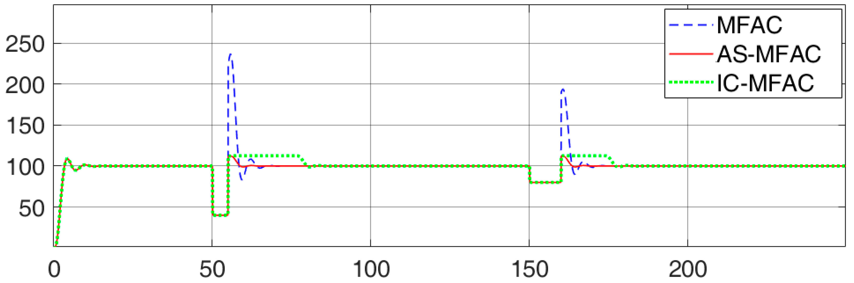
4.1.1. Algorithm Effect Comparison

To more clearly compare the traditional MFAC, MFAC with input constraint (IC-MFAC), and the AS-MFAC algorithms proposed in this paper, numerical simulations were conducted using Simulink software.
The designed simulation object is the second-order system as follows.
G ( s ) = 3 2 s 2 + 3 s + 4
The expected value is 100 and the simulation time is 250 s. The proposed model is used only to generate input and output data in this part of the study and does not contribute to the design of the controller. A forced variable is applied from 50 s to 60 s and from 150 s to 160 s to cause error accumulation. The parameters of the three algorithms are set as follows:  ρ = 0.3,   η = 1 , μ = 10, ε = 0.001, set ζ = 3, u m ( k ) = 150 for the AS-MFAC algorithm, and the constraint value of the IC-MFAC algorithm is set to 150 to resist saturation.
The simulation results are shown in Figure 5 and Figure 6.
As seen in Figure 5, when the actuator is saturated, the traditional MFAC algorithm (blue line) has controller saturation caused by great error accumulation, resulting in a very large output value. In the actual system, this situation would damage the controller. For the IC-MFAC algorithm, after the system undergoes controller saturation, the error accumulation is not eliminated and it takes a certain amount of time to restore normal control. As seen in Figure 6, the input value remains at the constraint value of 150 during the process of eliminating error accumulation. The AS-MFAC algorithm proposed in this paper has an obvious anti-saturation effect. After error accumulation, it quickly desaturates, eliminates the accumulated error, and tracks the expected value of the system.

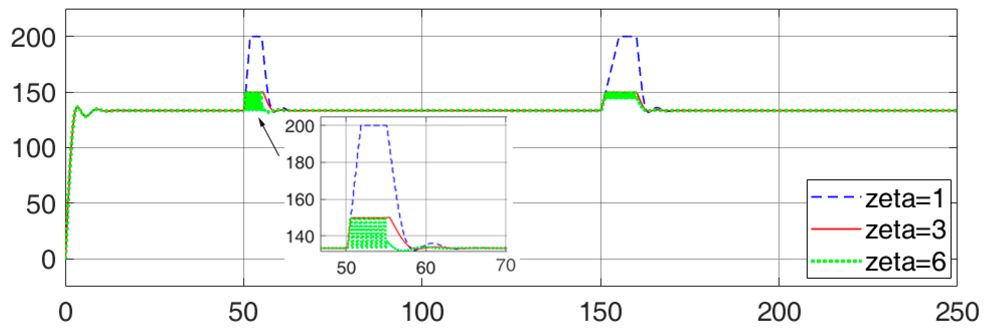
4.1.2. Key Parameters Analysis of AS-MFAC

As mentioned above, ζ is an important parameter for the AS-MFAC algorithm. Next, the influence of ζ on the anti-windup MFAC controller is simulated and analyzed. The values of ζ are 1, 3, and 6, and the other values remain unchanged. Figure 7 and Figure 8 are different output and input change curves corresponding to three types of ζ , respectively.
Figure 8 shows that in three cases, the AS-MFAC controller has a certain anti- saturation ability. When ζ is 1, the anti- saturation ability of the system is weak; when ζ is 6, the anti-saturation ability is strong but the desaturation is too large and the output is lower than the expected value for a period of time. According to the output in Figure 8, when the selected value of ζ is 6, the input of the system is stuck in the error accumulation stage, which has a certain adverse impact on the controller.

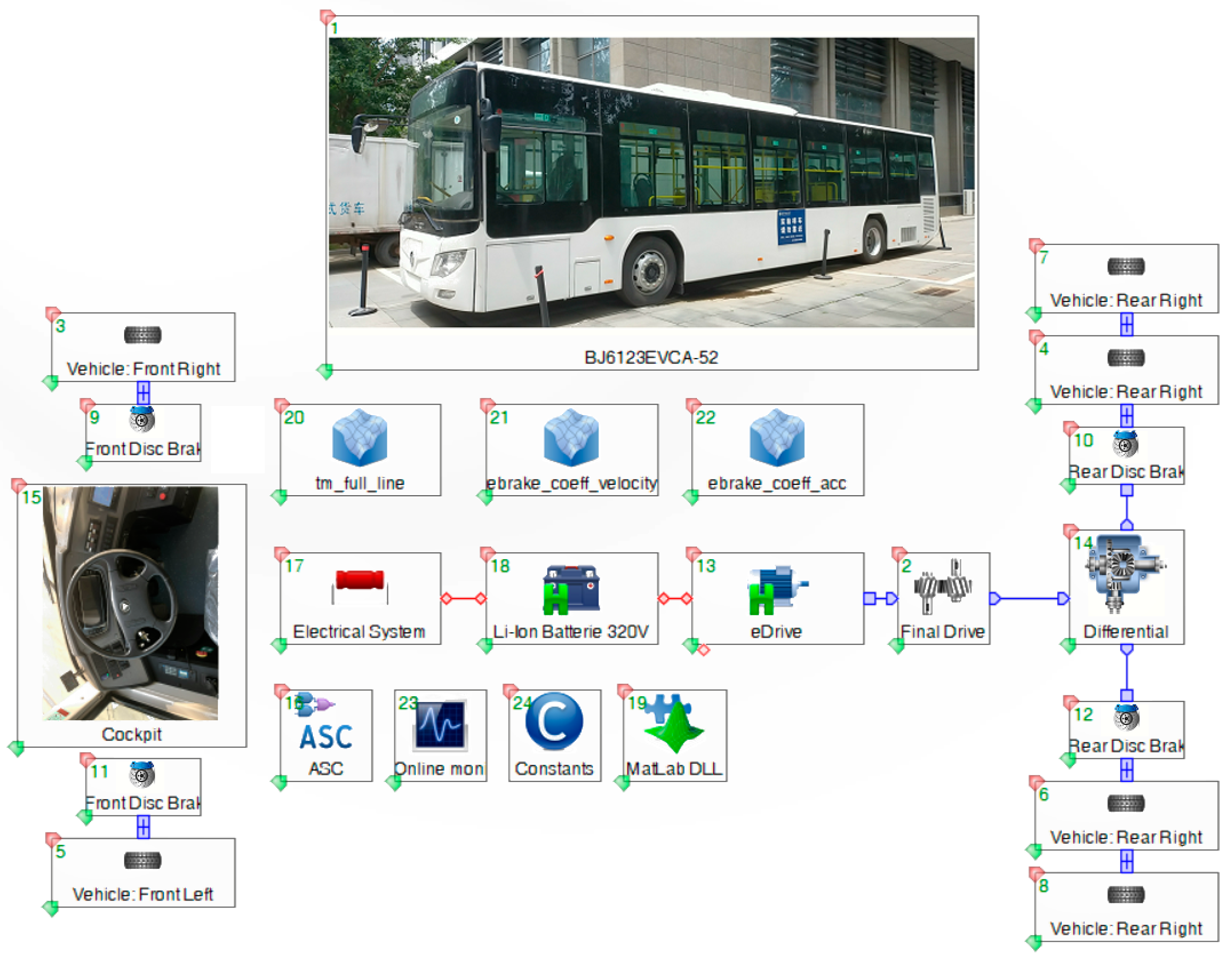
4.2. AVL Cruise Hardware in the Loop Simulation

In this part, AVL cruise simulation will be used to verify the impact of the proposed AS-MFAC on the braking energy recovery control system. A professional vehicle and powertrain simulation, as well as analysis software bring the advantages of multidisciplinary system simulation, which can simulate the vehicle’s power, fuel economy, emission performance, and braking performance. The simulation interface is shown in Figure 9. The vehicle braking strategy has been written in MATLAB and encapsulated in the Matlab DLL module to jointly control the vehicle with AVL cruise. The specific parameter information of the vehicle is shown in Table 2.

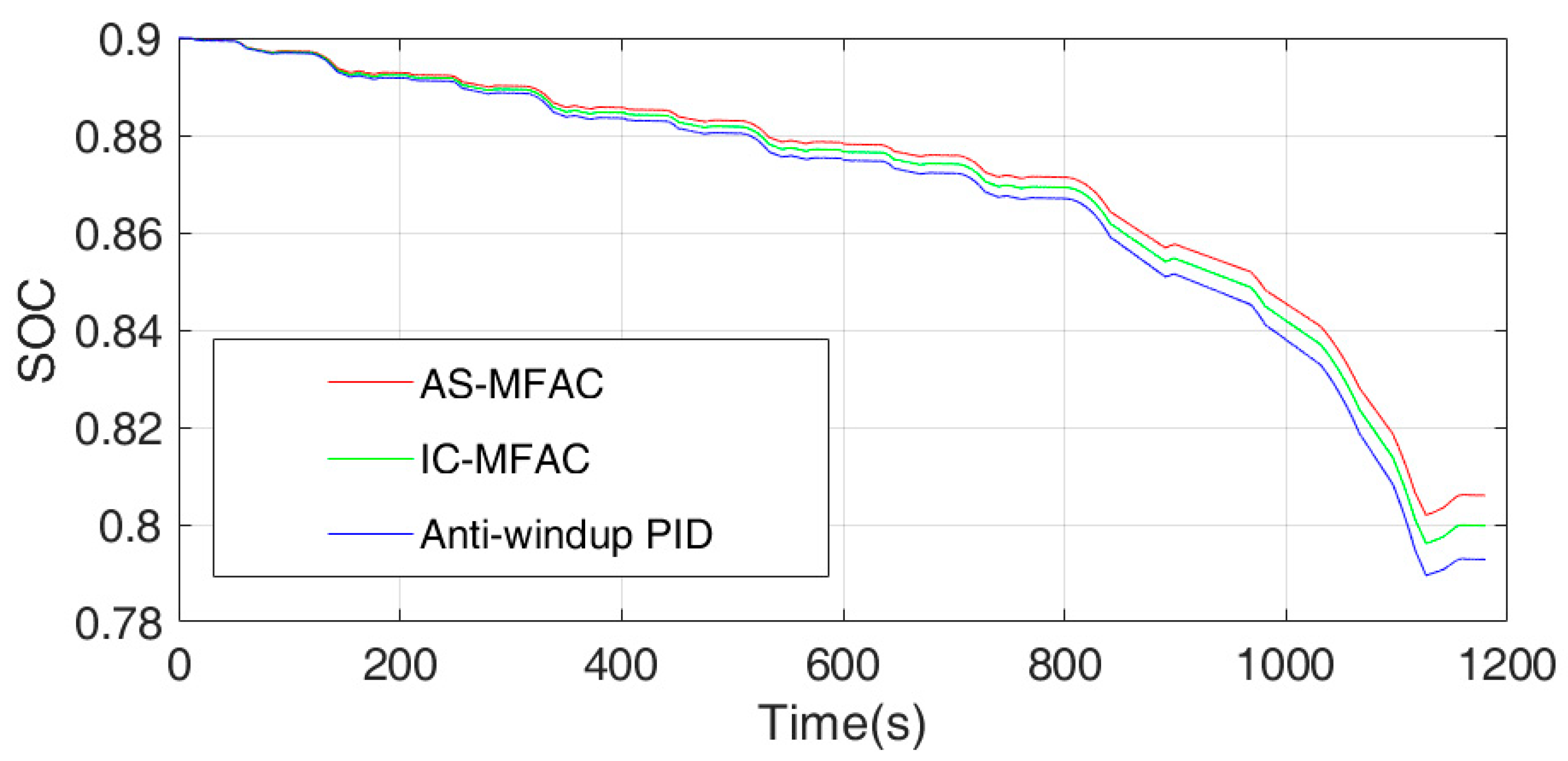
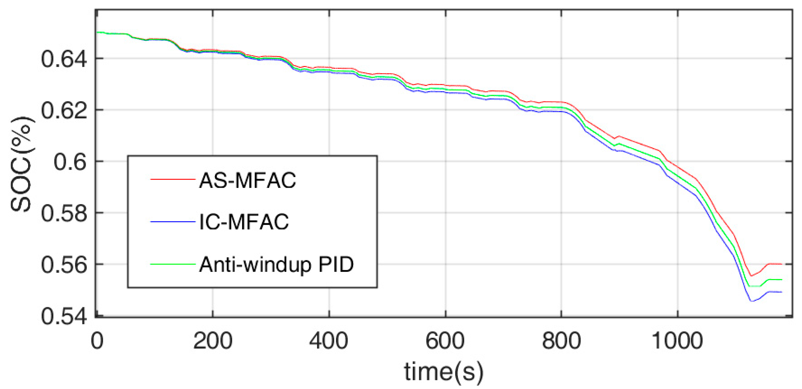
4.2.1. Battery Consumption Experiment

The distribution strategy of the braking force of the whole vehicle adopts the ideal braking force curve distribution strategy mentioned above. The simulation is under the New European Driving Cycle (NEDC) condition. The algorithm adopts the anti-windup PID (Proportional Integral Differential) algorithm, IC-MFAC algorithm, and AS-MFAC algorithm. The anti-windup PID algorithm is set as follows.
u ( k ) = K p e ( k ) + a K i i = 1 k 1 e ( i ) + K d [ e ( k ) e ( k 1 ) ]
a = { 1 | e ( k ) | τ 0 | e ( k ) | > τ
where τ a is a positive constant. The appropriate value of τ can affect the steady-state accuracy of the algorithm and reduce the influence of actuator saturation.
The optimum parameters of anti-windup PID obtained by the trial and error method are K p = 0.15, K i = 0.5, K d = 1.2, and τ = 210. The values of the AS-MFAC and IC-MFAC parameters are set as follows: ρ = 0.3, η = 1 , μ = 10, ε = 0.001, set ζ = 3, u m ( k ) = 1200 for the AS-MFAC algorithm, and the constraint value of the IC-MFAC algorithm is set to 1200 to resist saturation. The vehicle is set to be in a no-load state when starting the simulation. Passengers get on and off the vehicle at 226 s, 430 s, 577 s, and 775 s, and the operation of the complete working condition is typically 1200 s. When the initial SOC of the vehicle is 0.9, the change in the SOC is shown in Figure 10 and Figure 11.
By analyzing SOC curves of the simulation experiment under the NEDC working condition shown in Figure 10 and Figure 11, and the simulation results in Table 3 and Table 4, it can be concluded that there are two kinds of MFAC and anti-windup PID control strategy models after the 1200 s simulation experiment, wherein AS-MFAC has the highest energy recovery efficiency. If the vehicle consumes all the power, the vehicle under AS-MFAC can have about 12 km more conventional urban mileage than the vehicle under IC-MFAC control, and about 20 km more conventional urban mileage than the vehicle under anti-windup PID control, that is, under the control of AS-MFAC, the distribution of the braking force is more effective and more braking force is distributed to the rear wheels.

4.2.2. Speed Tracking Experiment

The speed control of the three algorithms on the vehicle under the NEDC test condition is shown in Figure 12. The AS-MFAC algorithm mentioned in this paper can track the vehicle speed well during braking. The control effect of anti-windup PID is slightly poor. Due to error accumulation, the IC-MFAC algorithm has the worst speed tracking ability among the three algorithms, which would have a certain impact on the safe driving of vehicles.

5. Conclusions

In this paper, aiming at the problem of braking energy recovery and braking force distribution between front and rear axles of pure electric bus, a novel AS-MFAC control method against saturation was designed. In the AS-MFAC method, the non-linear dynamics of the vehicle braking energy recovery process are first linearized via a novel dynamical linearization technique with a time-varying parameter pseudo partial derivative (PPD). Then, the AS-MFAC controller is designed via the proposed concept of a saturation parameter. Notably, the AS-MFAC control algorithm does not involve a system model and needs only input and output data of the system to complete the control task. Moreover, the stability of the AS-MFAC algorithm is proven by rigorous mathematical theory. The Simulink model simulation proves the controllability of the algorithm and the joint simulation of both AVL cruise and MATLAB proves the effectiveness of the algorithm in braking energy recovery.
The main contribution of this paper is as follows: the control method proposed in this paper can distribute more braking torque to the rear axle, as much as possible, while ensuring the braking efficiency and stability of the vehicle; improve the regenerative braking energy recovery rate; and eliminate the saturation problem caused by the error accumulation caused by composite braking.
In future work, we will continue to deeply study the proposed AS-MFAC algorithm and realize more complex functionality. The system will undergo various disturbances and become more complex. Therefore, the partial format dynamic linearization (PFDL) technology that can deal with more complex systems is adopted. At the same time, the distribution strategy between motor braking and friction braking will be further discussed.

Author Contributions

Conceptualization, H.J. and S.L.; methodology, Z.L. and S.L.; validation, S.L. and H.J.; formal analysis, S.L. and Z.L.; writing—original draft preparation, Z.L. and S.L.; writing—review and editing, Z.L. and S.L.; supervision, Z.H. and S.L.; project administration, S.L.; funding acquisition, L.W. All authors have read and agreed to the published version of the manuscript.

Funding

This work is supported by the Beijing Municipal Natural Science Foundation under grant 4212035 and 4204098; National Natural Science Foundation (NNSF) of China under grant 61903004 and 61833001; North China University of Technology Scientific Research Foundation; North China University of Technology Yu You Talent Training Program; and Beijing Municipal Great Wall Scholar Program (CIT&TCD20190304).

Institutional Review Board Statement

Not applicable.

Informed Consent Statement

Not applicable.

Data Availability Statement

Not applicable.

Conflicts of Interest

The authors declare that there are no conflict of interest.

Appendix A

In the appendix, we will first prove that in the case of saturation, the control system can desaturate in time and eliminate error accumulation in part 1. Then, it will be proven that the controller can make the desaturated system converge and stabilize in part 2.
Part 1:
If ϕ ^ c ( k ) ε , | Δ u ( k 1 ) | ε , or s i g n ( ϕ ^ c ( k ) ) s i g n ( ϕ ^ c ( 1 ) ) , then ϕ ^ c ( k ) is obviously bounded. ϕ ˜ c ( k ) = ϕ ^ c ( k ) ϕ c ( k ) can be defined as the estimation error of the PPD. Subtract ϕ c ( k ) from both sides of its parameter estimation to obtain:
ϕ ˜ c ( k ) = [ 1 η | Δ u ( k 1 ) | 2 μ + | Δ u ( k 1 ) | 2 ] ϕ ˜ c ( k 1 ) + ϕ c ( k 1 ) ϕ c ( k )
Take the absolute value on both sides of the above formula to obtain:
| ϕ ˜ c ( k ) | = | [ 1 η | Δ u ( k 1 ) | 2 μ + | Δ u ( k 1 ) | 2 ] | | ϕ ˜ c ( k 1 ) | + | ϕ c ( k 1 ) ϕ c ( k ) |
Note that function η | Δ u ( k 1 ) | 2 μ + | Δ u ( k 1 ) | 2 is monotonically increasing with respect to variable | Δ u ( k 1 ) | 2 and its minimum value is η ε 2 μ + ε 2 . Then, when 0 η 1 and μ 0 , there must be a constant d 1 , which satisfies:
0 | [ 1 η | Δ u ( k 1 ) | 2 μ + | Δ u ( k 1 ) | 2 ] | 1 η ε 2 μ + ε 2 = d 1 < 1
According to Theorem 1, ϕ c ( k ) is bounded and | ϕ c ( k ) | b , | ϕ c ( k 1 ) ϕ c ( k ) | 2 b , and b are constant. Using Equations (20) and (21), the following inequalities are obtained:
| ϕ ˜ c ( k ) | d 1 | ϕ ˜ c ( k 1 ) | + 2 b d 1 2 | ϕ ˜ c ( k 2 ) | + 2 d 1 b + 2 b d 1 k 1 | ϕ ˜ c ( 1 ) | + 2 b ( 1 d 1 k 1 ) 1 d 1
The above formula means that ϕ ˜ c ( k ) a is bounded and because ϕ c ( k ) is bounded, ϕ ^ c ( k ) is bounded.
When the system is in the state of integral saturation, namely e * ( k ) 0 , Γ ( k ) 0 , then e * ( k ) Γ ( k ) 0 . According to the reset algorithm:
ρ ϕ ^ c ( k ) λ + | ϕ ^ c ( k ) | 2 > 0
Then, u ( k ) < u ( k 1 ) ; in this state, u ( k ) is monotonically decreasing and u ( k ) can obviously recover below u m ( k ) . When u ( k ) returns below u m ( k ) , the system releases the integral saturation state.
Part 2:
When the integral saturation state of the system is released, the Lyapunov function is assumed:
V ( k ) = e 2 ( k )
Then,
Δ V ( k + 1 ) = V ( k + 1 ) V ( k ) = ( Δ e ( k + 1 ) + e ( k ) ) 2 e 2 ( k )
In the case of y * ( k + 1 ) = y * ( k ) :
Δ e ( k + 1 ) = ( y * ( k + 1 ) y ( k + 1 ) ) ( y * ( k ) y ( k ) ) = ( y * ( k + 1 ) y * ( k ) ) + ( y ( k ) y ( k + 1 ) ) = Δ y ( k + 1 )
Bring Equation (11) into Equation (A5) to obtain:
Δ V ( k + 1 ) = ( ϕ c ( k ) Δ u ( k ) + e ( k ) ) 2 e 2 ( k ) = ( ϕ c ( k ) ρ ϕ ^ c ( k ) λ + | ϕ ^ c ( k ) | 2 e ( k ) Γ ( k ) + e ( k ) ) 2 e 2 ( k ) = ( 1 ϕ c ( k ) ρ ϕ ^ c ( k ) λ + | ϕ ^ c ( k ) | 2 e ( k ) Γ ( k ) ) 2 e 2 ( k ) e 2 ( k )
According to the reset algorithm, ϕ c ( k ) ϕ ^ c ( k ) > 0 and Γ ( k ) = 1.
Let λ min = b 2 4 . Using inequality α 2 + β 2 2 α β , the guarantee condition ϕ ^ c ( k ) ε of the reset algorithm, and the boundedness of ϕ ^ c ( k ) , it can be seen that if λ > λ min is selected, there must be a constant 0 < M < 1 so that the following formula holds:
0 < M ϕ c ( k ) ϕ ^ c ( k ) λ + | ϕ ^ c ( k ) | 2 Γ ( k ) b ϕ ^ c ( k ) λ + | ϕ ^ c ( k ) | 2 b ϕ ^ c ( k ) 2 λ ϕ ^ c ( k ) < b ϕ ^ c ( k ) 2 λ min ϕ ^ c ( k ) = 1
According to Equation (A7), 0 < ρ < 1 , and λ > λ min , there must be a constant d 2 such that:
| 1 ϕ c ( k ) ρ ϕ ^ c ( k ) λ + | ϕ ^ c ( k ) | 2 Γ ( k ) | = 1 ϕ c ( k ) ρ ϕ ^ c ( k ) λ + | ϕ ^ c ( k ) | 2 Γ ( k ) 1 ρ M = d 2 < 1
Then,
Δ V ( k + 1 ) = d 2 e 2 ( k ) e 2 ( k ) < 0
The system is asymptotically stable. Theorem 2 is proved.

References

  1. Zhongshi, Z.; Ruihai, M.; Lifang, W.; Junzhi, Z. Novel PMSM Control for Anti-Lock Braking Considering Transmission Properties of the Electric Vehicle. IEEE Trans. Veh. Technol. 2018, 67, 10378–10386. [Google Scholar] [CrossRef]
  2. Król, A.; Sierpiński, G. Application of a Genetic Algorithm With a Fuzzy Objective Function for Optimized Siting of Electric Vehicle Charging Devices in Urban Road Networks. IEEE Trans. Intell. Transp. Syst. 2021, 1–12. [Google Scholar] [CrossRef]
  3. Mehta, S.; Hemamalini, S. A Dual Control Regenerative Braking Strategy for Two-Wheeler Application. Energy Procedia 2017, 117, 299–305. [Google Scholar] [CrossRef]
  4. Hardman, S.; Chandan, A.; Tal, G.; Turrentine, T. The effectiveness of financial purchase incentives for battery electric vehicles—A review of the evidence. Renew. Sustain. Energy Rev. 2017, 80, 1100–1111. [Google Scholar] [CrossRef]
  5. Gao, Y.; Chen, L.; Ehsani, M. Investigation of the Effectiveness of Regenerative Braking for EV and HEV. SAE Trans. 1999, 108, 3184–3190. [Google Scholar]
  6. Masih-Tehrani, M.; Dahmardeh, M. A Novel Power Distribution System Employing State of Available Power Estimation for a Hybrid Energy Storage System. IEEE Trans. Ind. Electron. 2018, 65, 6676–6685. [Google Scholar] [CrossRef]
  7. Jung, S.; Ko, J. Study on Regenerative Energy RecoSvery of Electric Vehicle Through Voltage Control Using Switched Capacitor. IEEE Trans. Veh. Technol. 2021, 70, 4324–4339. [Google Scholar] [CrossRef]
  8. Ko, J.; Ko, S.; Son, H.; Yoo, B.; Cheon, J.; Kim, H. Development of Brake System and Regenerative Braking Cooperative Control Algorithm for Automatic-Transmission-Based Hybrid Electric Vehicles. IEEE Trans. Veh. Technol. 2015, 64, 431–440. [Google Scholar] [CrossRef]
  9. Heydari, S.; Fajri, P.; Rasheduzzaman, M.; Sabzehgar, R. Maximizing Regenerative Braking Energy Recovery of Electric Vehicles Through Dynamic Low-Speed Cutoff Point Detection. IEEE Trans. Transp. Electrif. 2019, 5, 262–270. [Google Scholar] [CrossRef]
  10. Fujiki, N.; Koike, Y.; Ito, Y.; Suzuki, G.; Gotoh, S.; Yukio, O.; Yamagucki, T. Development of an Electrically-Driven Intelligent Brake System for EV. Autom. Veh. Technol. 2011, 65, 399–405. [Google Scholar] [CrossRef]
  11. Aldred, C. Brake applied to recall cover. Bus. Insur. 2004, 38, 1. [Google Scholar]
  12. Aoki, Y.; Suzuki, K.; Nakano, H.; Nojiri, Y.; Shirase, T.; Sakai, K. Development of Hydraulic Servo Brake System for Hybrid Vehicle. Trans. Soc. Automot. Eng. Jpn. 2007, 38, 25–30. [Google Scholar]
  13. Nakamura, E.; Soga, M.; Sakai, A.; Otomo, A.; Kobayashi, T. Development of Electrically Controlled Brake System for Hybrid Vehicle; SAE Technical Papers; SAE International: Warrendale, PA, USA, 2002; Volume 2, pp. 129–137. [Google Scholar]
  14. Rigaut, T.; Carpentier, P.; Chancelier, J.P.; De Lara, M.; Waeytens, J. Stochastic Optimization of Braking Energy Storage and Ventilation in a Subway Station. IEEE Trans. Power Syst. 2019, 34, 1256–1263. [Google Scholar] [CrossRef]
  15. Peng, H.; Wang, W.; Xiang, C.; Li, L.; Wang, X. Torque Coordinated Control of Four In-Wheel Motor Independent-Drive Vehicles With Consideration of the Safety and Economy. IEEE Trans. Veh. Technol. 2019, 68, 9604–9618. [Google Scholar] [CrossRef]
  16. Xu, W.; Chen, H.; Zhao, H.; Ren, B. Torque optimization control for electric vehicles with four in-wheel motors equipped with regenerative braking system. Mechatronics 2019, 57, 95–108. [Google Scholar] [CrossRef]
  17. Guoqing, X.; Kun, X.; Chunhua, Z.; Xinye, Z.; Taimoor, Z. Fully Electrified Regenerative Braking Control for Deep Energy Recovery and Maintaining Safety of Electric Vehicles. IEEE Trans. Veh. Technol. 2016, 65, 1186–1198. [Google Scholar] [CrossRef]
  18. Fnadi, M.; Du, W.; Plumet, F.; Benamar, F. Constrained Model Predictive Control for dynamic path tracking of a bi-steerable rover on slippery grounds. Control Eng. Pract. 2021, 107, 104693. [Google Scholar] [CrossRef]
  19. Gao, J.; Zhang, G.; Wu, P.; Zhao, X.; Wang, T.; Yan, W. Model Predictive Visual Servoing of Fully-Actuated Underwater Vehicles With a Sliding Mode Disturbance Observer. IEEE Access 2019, 7, 25516–25526. [Google Scholar] [CrossRef]
  20. Fnadi, M.; Alexandre dit Sandretto, J. Experimental Validation of a Guaranteed Nonlinear Model Predictive Control. Algorithms 2021, 14, 248. [Google Scholar] [CrossRef]
  21. Zhang, Y.; Zhang, H.; Yang, C.; Xiang, C.; Li, L. Research on predictive control strategy for efficient braking energy recovery of hybrid electric bus based on new improved genetic algorithm. J. Mech. Eng. 2020, 56, 11. [Google Scholar]
  22. Deng, R.; Liu, Y.; Chen, W.; Liang, H. A Survey on Electric Buses—Energy Storage, Power Management, and Charging Scheduling. IEEE Trans. Intell. Transp. Syst. 2021, 22, 9–22. [Google Scholar] [CrossRef]
  23. Huang, X.; Wang, J. Model Predictive Regenerative Braking Control for Lightweight Electric Vehicles with in-Wheel Motors. J. Automob. Eng. 2012, 226, 1220–1232. [Google Scholar] [CrossRef]
  24. Yaonan, W.; Xizheng, Z.; Xiaofang, Y.; Guorong, L. Position-Sensorless Hybrid Sliding-Mode Control of Electric Vehicles With Brushless DC Motor. IEEE Trans. Veh. Technol. 2011, 60, 421–432. [Google Scholar] [CrossRef]
  25. Wang, C.; Zhao, W.; Li, W. Braking sense consistency strategy of electro-hydraulic composite braking system. Mech. Syst. Signal Process. 2018, 109, 196–219. [Google Scholar] [CrossRef]
  26. Hoang, H.S.; Baraille, R. A simple numerical method based simultaneous stochastic perturbation for estimation of high dimensional matrices. Multidimens. Syst. Signal Process. 2018, 30, 195–217. [Google Scholar] [CrossRef]
  27. Hou, Z.; Jin, S. A Novel Data-Driven Control Approach for a Class of Discrete-Time Nonlinear Systems. IEEE Trans. Control Syst. Technol. 2011, 19, 1549–1558. [Google Scholar] [CrossRef]
  28. Safonov, M.G.; Tsao, T.-C. The unfalsified control concept and learning. IEEE Trans. Autom. Control 1997, 42, 843–847. [Google Scholar] [CrossRef]
  29. Hjalmarsson, H.; Gevers, M.; Gunnarsson, S.; Lequin, O. Iterative Feedback Tuning: Theory and Applications. IEEE Control Syst. 1998, 18, 26–41. [Google Scholar] [CrossRef]
  30. Previde, F.; Belloli, D.; Cologne, A.; Savaresi, S.M. Virtual Reference Feedback Tuning (VRFT) Design of Cascade Control Systems with Application to an Electro-Hydrostatic Actuator. IFAC Proc. Vol. 2010, 43, 626–632. [Google Scholar] [CrossRef]
  31. Meng, D.; Moore, K.L. Robust Iterative Learning Control for Nonrepetitive Uncertain Systems. IEEE Trans. Autom. Control 2017, 62, 907–913. [Google Scholar] [CrossRef]
  32. Ji, H.; Wei, Y.; Fan, L.; Liu, S.; Wang, Y.; Wang, L. Disturbance-Improved Model-Free Adaptive Prediction Control for Discrete-Time Nonlinear Systems with Time Delay. Symmetry 2021, 13, 2128. [Google Scholar] [CrossRef]
  33. Shida, L.; Zhongsheng, H.; Taotao, T.; Zhidong, D.; Zhenxuan, L. A Novel Dual Successive Projection-Based Model-Free Adaptive Control Method and Application to an Autonomous Car. IEEE Trans. Neural Netw. Learn. Syst. 2019, 30, 3444–3457. [Google Scholar] [CrossRef]
  34. Coelho, L.; Coelho, A. Model-free adaptive control optimization using a chaotic particle swarm approach. Chaos Solitons Fractals 2009, 41, 2001–2009. [Google Scholar] [CrossRef]
  35. Rong-Jong, W.; Zhi-Wei, Y. Adaptive Fuzzy Neural Network Control Design via a T–S Fuzzy Model for a Robot Manipulator Including Actuator Dynamics. IEEE Trans. Syst. Man Cybern. 2019, 38, 1326–1346. [Google Scholar] [CrossRef]
  36. Tan, K.K.; Lee, T.H.; Huang, S.N.; Leu, F.M. Adaptive-Predictive Control of a Class of SISO Nonlinear Systems. Dyn. Control 2001, 11, 151–174. [Google Scholar] [CrossRef]
  37. Li, W.; Du, H.; Li, W. Four-Wheel Electric Braking System Configuration With New Braking Torque Distribution Strategy for Improving Energy Recovery Efficiency. IEEE Trans. Intell. Transp. Syst. 2020, 21, 87–103. [Google Scholar] [CrossRef]
  38. Jabbour, N.; Mademlis, C. Supercapacitor-Based Energy Recovery System With Improved Power Control and Energy Management for Elevator Applications. IEEE Trans. Power Electron. 2017, 32, 9389–9399. [Google Scholar] [CrossRef]
  39. Ni, J.; Hu, J.; Xiang, C. Control-Configured-Vehicle Design and Implementation on an X-by-Wire Electric Vehicle. IEEE Trans. Veh. Technol. 2018, 67, 3755–3766. [Google Scholar] [CrossRef]
  40. Xudong, Z.; Dietmar, G.; Jiayuan, L. Energy-Efficient Toque Allocation Design of Traction and Regenerative Braking for Distributed Drive Electric Vehicles. IEEE Trans. Veh. Technol. 2018, 67, 285–295. [Google Scholar] [CrossRef]
  41. Wang, J.C.; He, R.; Kim, Y.B. Optimal Anti-Lock Braking Control With Nonlinear Variable Voltage Charging Scheme for an Electric Vehicle. IEEE Trans. Veh. Technol. 2020, 69, 7211–7222. [Google Scholar] [CrossRef]
  42. Liu, B.; Li, L.; Wang, X.; Cheng, S. Hybrid Electric Vehicle Downshifting Strategy Based on Stochastic Dynamic Programming During Regenerative Braking Process. IEEE Trans. Veh. Technol. 2018, 67, 4716–4727. [Google Scholar] [CrossRef]
  43. Liang, C.; Qiang, H.; Zicheng, F.; Zhe, L.; Yanwen, P. Research on regenerative braking control strategy of pure electric vehicle. J. Automot. Eng. 2016, 5, 244–251. [Google Scholar]
  44. Kumar, G.V.; Chuang, C.H.; Lu, M.Z.; Liaw, C.-M. Development of an Electric Vehicle Synchronous Reluctance Motor Drive. IEEE Trans. Veh. Technol. 2020, 69, 5012–5024. [Google Scholar] [CrossRef]
  45. Naranjo, W.; Camargo, L.E.M.; Pereda, J.E.; Cortes, C. Design of Electric Buses of Rapid Transit Using Hybrid Energy Storage and Local Traffic Parameters. IEEE Trans. Veh. Technol. 2017, 66, 5551–5563. [Google Scholar] [CrossRef]
  46. Tavernini, D.; Vacca, F.; Metzler, M.; Savitski, D.; Ivanov, V.; Gruber, P.; Hartavi, A.E.; Dhaens, M.; Sorniotti, A. An Explicit Nonlinear Model Predictive ABS Controller for Electro-Hydraulic Braking Systems. IEEE Trans. Ind. Electron. 2019, 67, 3990–4001. [Google Scholar] [CrossRef]
  47. Donghyun, K.; Chulsoo, K.; Sungho, H.; Hyunsoo, K. Hardware in the Loop Simulation of Vehicle Stability Control using Regenerative Braking and Electro Hydraulic Brake for Hybrid Electric Vehicle. IFAC Proc. Vol. 2008, 41, 5664–5669. [Google Scholar] [CrossRef] [Green Version]
  48. Fnadi, M.; Plumet, F.; Benamar, F. Nonlinear Tire Cornering Stiffness Observer for a Double Steering Off-Road Mobile Robot. In Proceedings of the 2019 International Conference on Robotics and Automation (ICRA), Montreal, QC, Canada, 20–24 May 2019. [Google Scholar]
  49. Oudghiri, M.; Chadli, M.; Hajjaji, A.E. Lateral vehicle velocity estimation using fuzzy sliding mode observer. In Proceedings of the Conference on Control & Automation, Ajaccio, France, 25–27 June 2008. [Google Scholar]
Figure 1. Mazda i-eloop braking energy recovery system.
Symmetry 14 00580 g001
Figure 2. Basic principle of the braking energy recovery system.
Symmetry 14 00580 g002
Figure 3. Stress diagram of a pure electric bus.
Symmetry 14 00580 g003
Figure 4. Line I of the pure electric bus.
Symmetry 14 00580 g004
Figure 5. Control output of the traditional MFAC, AS-MFAC, and IC-MFAC algorithms.
Symmetry 14 00580 g005
Figure 6. Control input of the traditional MFAC, AS-MFAC, and IC-MFAC algorithms.
Symmetry 14 00580 g006
Figure 7. Output curves when the value of ζ is 1, 3, and 6.
Symmetry 14 00580 g007
Figure 8. Input curves when the value of ζ is 1, 3, and 6.
Symmetry 14 00580 g008
Figure 9. AVL cruise hardware in the loop simulation interface.
Symmetry 14 00580 g009
Figure 10. SOC initial value is 0.9. SOC change curve under three different algorithms under NEDC working condition.
Symmetry 14 00580 g010
Figure 11. SOC initial value is 0.65. SOC change curve under three different algorithms under NEDC working condition.
Symmetry 14 00580 g011
Figure 12. Vehicle speed variation curve under three different algorithms under NEDC working condition.
Symmetry 14 00580 g012
Table 1. Technical parameters of BAIC BJ6123EVCA-52.
Parameter NameSymbolNumerical Value
Curb weight (complete vehicle) kg11,600/12,000
Wheelbasemm5900
Front suspensionmm2670
Rear suspensionmm3430
Maximum number of passengersperson60
Table 2. Main parameters of the whole vehicle.
ParameterSymbolNumerical Value
Speed ratio of the main reducer/6.058
Transmission speed ratio/1
Transmission efficiency/0.96
Wheel rolling radiusmm507
Linear resistanceN0.0
Square resistance N0.03399
Constant resistance/143.06
Rated voltage/maximum voltage V320/420
Table 3. SOC initial value is 0.9. SOC data under three different algorithms under NEDC working condition.
MethodAS-MFACIC-MFACAnti-windup PID
Initial SOC90%90%90%
Final SOC80.599%79.978%79.282%
Table 4. SOC initial value is 0.65. SOC data under three different algorithms under NEDC working condition.
MethodAS-MFACIC-MFACAnti-windup PID
Initial SOC65%65%65%
Final SOC55.995%55.387%54.908%
Publisher’s Note: MDPI stays neutral with regard to jurisdictional claims in published maps and institutional affiliations.

