Article

A 32-Bit DSP Instruction Pipeline Control Unit Verification Method Based on Instruction Reordering Strategy

School of Computer, National University of Defense Technology, Changsha 410073, China
*
Author to whom correspondence should be addressed.
Symmetry 2022, 14(4), 646; https://doi.org/10.3390/sym14040646
Submission received: 6 March 2022 / Revised: 18 March 2022 / Accepted: 21 March 2022 / Published: 22 March 2022
(This article belongs to the Section Computer)

Abstract

:
The growing complexity and size of integrated circuits has made functional verification a huge challenge. As the control center of integrated circuit hardware design, any design errors in the Instruction Pipeline Control Unit (IPCU) will put the entire chip at significant risk. Verification of the IPCU has accordingly become a substantial challenge for test engineers. Taking a 32-bit VLIW DSP as the research goal, this paper proposes a directional random verification method for IPCU based on the instruction reordering strategy (InstRO). First, according to the symmetry of input and output of the instruction pipeline, this method considers several functional components as a whole and establishes a high-level reference model based on the instruction reordering strategy (InstRO-Model), thereby both shielding the complex logic inside the hardware design and reducing the complexity of the verification model. Second, by automatically generating random test stimuli, the constraints of which can be adjusted in a particular direction, effective intensive testing of different functional points of the design under test (DUT) is realized, and code coverage and functional coverage are both improved. Finally, the test stimuli are input into the InstRO-Model and the DUT at the same time. As the input and output of the InstRO-Model also have symmetry with the input and output of the DUT, an automatic comparison of the verification results is realized via assertions. This approach greatly reduces the manpower and time required for verification and improves the verification efficiency. Experiments and practical application results show that this method can increase the code coverage to more than 99%. In particular, efficient directional random verification can be carried out for the weak points in the instruction pipeline control verification and the function points that are difficult to manually simulate and traverse, which greatly improves the verification efficiency and verification integrity of the IPCU.

1. Introduction

Along with the rapid development of deep learning algorithms based on integrated circuit hardware in applications such as artificial intelligence, autonomous driving, and biomedicine, the scale of integrated circuit hardware design has gradually expanded. There are now numerous excellent deep learning hardware-accelerated processors available, the architecture of which incorporates precise instruction pipeline control, a large number of arithmetic/logical operation units, and abundant on-chip storage resources [1,2,3]. Among their components, the Instruction Pipeline Control Unit (IPCU) can be considered the brain of the processor, as it controls the program execution sequence and implements operations such as sequential program execution, branch pipeline control, and interrupt processing. The expansion of the function and scale of hardware accelerators has increased the complexity of the instruction pipeline; at the same time, correctly implementing precise control has become increasingly challenging. In an application scenario with complex control, no matter how powerful the processor’s computing power and how rich the on-chip storage capacity, the consequences of an instruction pipeline control error are enough to cause the chip to enter a state of paralysis. Therefore, the efficient, complete, and accurate verification of instruction pipeline control is an important problem that must be overcome in the design and verification of microprocessors.
There are two main verification methods for processor logic design [4,5]: directional functional verification based on simulation, and formal verification based on random stimulus. Simulation-based directional functional verification generally adopts a manual writing approach and performs test incentives for specified functions, including module-level verification and system-level verification. The directional function verification method has a high subjective dependence, such that the correctness, efficiency and completeness of its verification are closely related to the level of experience possessed by the verification personnel [6]. Moreover, because the directional functional verification is often compiled manually for a specific module, the reusability of the stimuli tends to be low [7,8]. Formal verification based on random excitation can traverse the state of the design, and the verification coverage is high [9]. However, in a complex control system, an increase in control flow will lead to an explosion in the exploration space. In addition, the writing of random incentive constraints requires verifiers to have a high level of design experience; otherwise, there may be a verification-blind area of random incentives or a repeated coverage of verification function points, which will reduce verification efficiency [10,11].
FT-xDSP is a high-performance 32-bit Digital Signal Processor independently developed by our company [12]. This paper takes the IPCU of FT-xDSP as the research object and proposes a directional random IPCU verification method based on the instruction reordering strategy. By intelligently dividing the logic of the command flow control component, the interface protocol between the command flow control component and the outside is simplified, and the difficulty of random verification is reduced. Moreover, for those function points for which it is difficult to carry out directional simulation verification, the directional random excitation automatically generates and tests results for automatic comparative analysis. The experimental and actual verification results show that our proposed method can find hidden verification edge cases and conduct directional random verification for weak points in the design, thereby greatly improving the verification efficiency of instruction pipeline control. The main contributions of this paper can be summarized as follows:
  • First, by analyzing the architecture and function points of the IPCU, an efficient and portable abstract model based on the instruction reordering strategy is established. According to the symmetry of input and output of the instruction pipeline, the complex logic inside the hardware design and the external complex interface protocol are shielded, which reduces the complexity of verification;
  • Second, we automatically generate random test stimuli with constraints and implement effective intensive testing of different functional points of the design under test (DUT) by directionally adjusting the test stimulus generation method, thereby improving code coverage and functional coverage;
  • Finally, according to the symmetry of the DUT and the model, the results of the reference model and the DUT are automatically compared and analyzed by means of assertion, which greatly reduces the manpower and time required for verification and improves the verification efficiency.
Experiments and practical application results show that this method can perform directional random verification for the weak points in the IPCU, which greatly improves the verification efficiency and verification integrity of the IPCU. In addition, owing to its high portability, this verification method can be applied to many DSP chips with similar architecture.
The remainder of this paper is organized as follows. Section 2 presents related research work on IPCU verification methods. In Section 3, an efficient and portable directional random verification method of DSP instruction pipeline control based on the instruction reordering strategy is proposed for the instruction pipeline control architecture of FT-xDSP. Section 4 provides an analysis of the experimental results. Finally, Section 5 concludes this paper.

2. Related Work

In this section, we will discuss common hardware design verification methods, as well as methods for evaluating verification effectiveness.

2.1. Simulation-Based Directed Functional Verification

The simulation-based directional functional verification method involves writing test stimuli for each individual function point. This method is generally used in the initial stage of verification to check simple functional errors, or in cases where there are few combinations of input states, such as modules with simple design functions [13,14,15]. Since Directed Functional Verification is manually programmed for specific modules and functions, the resulting verification incentives can rarely be reused with other designs. The IPCU of FT-xDSP has a multi-stage pipeline, and the state design is complex; accordingly, the verifier must have a sufficiently deep understanding of the logic design to write an effective test stimulus. At the same time, the output results of the directional verification excitation also require manual analysis. For pipeline states with complex control logic, the results analysis stage is highly time-consuming, and is also prone to analysis errors or the omission of some corner function points [16,17].

2.2. Formal Verification Based on Random Stimulus

The random stimulus-based formal verification method generates a constrained random input combination by analyzing the input of the DUT, then performs state traversal on the design, which has a high verification coverage [18,19,20]. Because of the state traversal, this method is generally used in designs with simple logic functions [21]. In complex control systems or large-scale designs, formal verification will lead to the problem of exploration space explosion. Therefore, improving the legitimacy and effectiveness of the random stimuli is the key to increasing verification efficiency.

2.3. Verification Method Based on Reference Models

Reference model-based verification can be further subdivided into traditional verification and formal verification. This method is generally suitable for the module-level verification of data-intensive designs (such as DMA, Cache, arithmetic units, etc.) [6], or system-level processors. In module-level verification, the DUT often have simple input and output control logic and are easy to model; examples include the reference model-based verification methods used in the following literature [22,23,24,25]. In processor system-level verification, a higher-level language is often used to describe the behavior of the processor, and a software simulator is built to determine whether the execution results of the simulator and the processed program are consistent (often by comparing the operation results in registers or memory) [26,27]. This verification method is applicable to RISC and CISC processors, VLIW processors [28], and even mainframe central processing [29,30]. The system-level reference model has a large scale, and is generally applicable to cases in which the basic functions of the processor have been verified. A large number of algorithms and library functions are used to verify the processor at an application level [31].
For complex control designs such as IPCU, interrupt control systems, etc., the external protocols and internal functions are characterized by high complexity, meaning that it is difficult to generate random excitations and construct reference models at the module level. Complex control designs are often embedded in the entire DSP core system-level environment for system-level simulation verification, or for system-based reference model (simulator) verification. This system-level verification has certain disadvantages, such as inconvenient debugging, inability to run in large batches, and slow EDA software simulation.

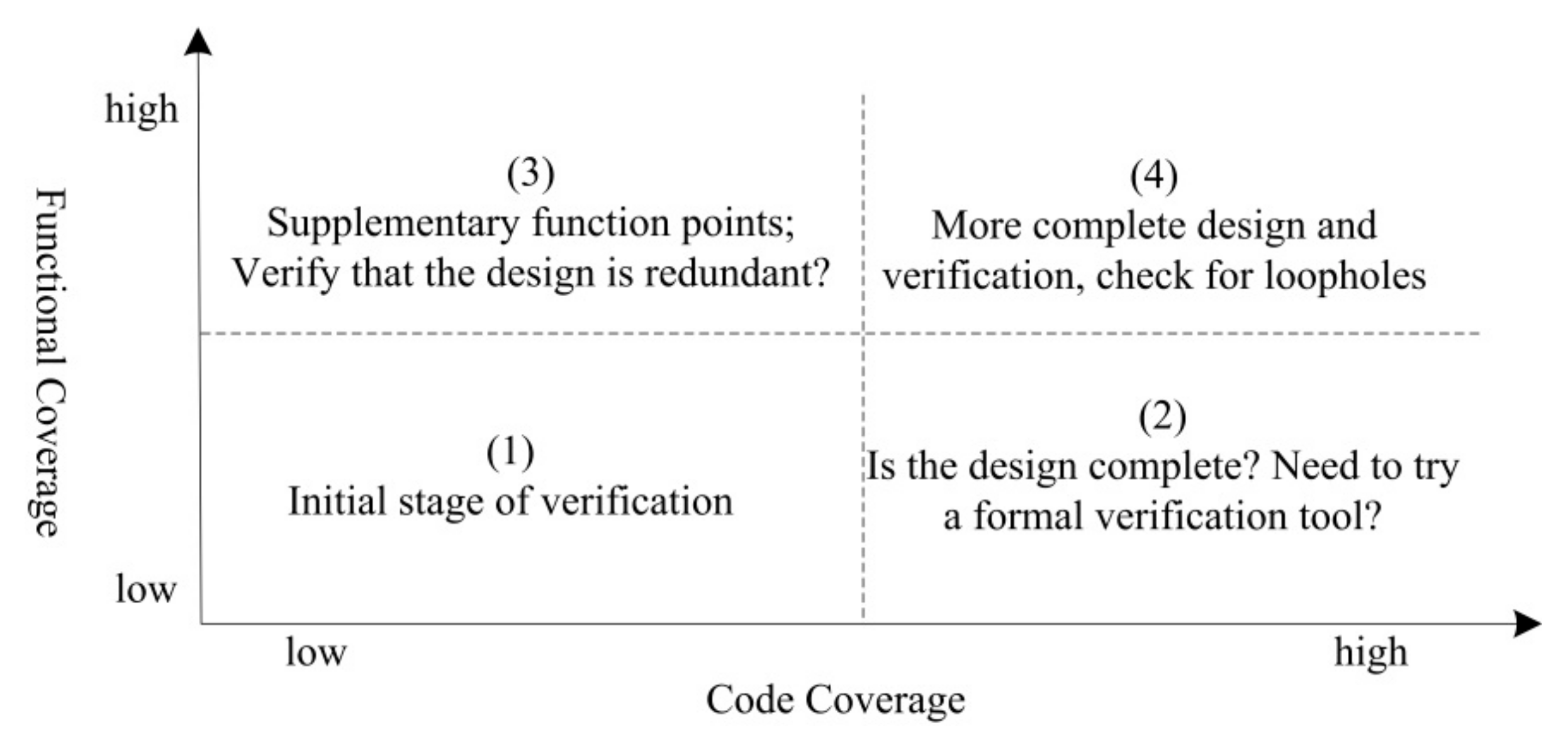
2.4. Validation Effectiveness Evaluation

The ultimate goal of hardware verification is to achieve a high level of coverage in order to ensure completeness and the correctness of functions. Coverage can be broadly subdivided into code coverage, functional coverage and assertion coverage [4]. In coverage-driven verification, reference to functional coverage and code coverage enables a quick assessment of the current design and verification situation, as shown in Figure 1. In the early stages of verification, both functional coverage and code coverage tend to be low. As the work of verification progresses, high functional coverage and high code coverage are eventually obtained. If these two coverage ratios are inconsistent, it may be necessary to consider whether the design is reasonable, whether the function point extraction is accurate, and whether a formal verification tool is needed to assist in state traversal [32,33,34,35].

2.5. Summary

The various verification methods in this chapter are summarized in Table 1.

3. Proposed Verification Method

Section 3.1 provides an overview of the microarchitecture of the FT-xDSP IPCU and summarizes the verification function points, clarifying the challenges associated with IPCU verification. Based on the above analysis, an Instruction-ReOrdering (InstRO) verification strategy is proposed. Section 3.2 proposes a reference model based on InstRO (InstRO-Model) and discusses its method of implementation. Finally, Section 3.3 introduces the method used to automatically generate the random stimuli of InstRO-Model and conduct the automatic comparative analysis of the results.

3.1. Overview of IPCU Verification

3.1.1. IPCU Architecture of FT-xDSP

FT-xDSP is a high-performance floating-point vector DSP independently developed by the National Defense University of Science and Technology. It adopts a VLIW-based scalar/vector cooperative architecture, a 16/32-bit variable-length instruction set, and can issue 1 to 11 instructions in parallel in a single clock cycle [9]. The IPCU of FT-xDSP chiefly comprises an instruction fetching unit (PG, PW, PQ; three-stage pipeline), instruction dispatching unit (DP1, DP2; two-stage pipeline) and branch instruction processing components (BR), as shown in Figure 2. Among them, PG generates an instruction fetch packet (FP, 512-bit alignment) request address based on the branches, interrupts sequential self-adding addresses, and requests an instruction packet from the program memory (PM). DP1 accepts the instruction FP from the instruction fetch component, or PM, splices and decodes FP, and then dispatches instructions to the corresponding functional unit via DP2. BR processes the pipeline control instructions and changes the trajectory of the program (such as branch instructions, interrupt return instructions, etc.). The other 10 functional units (FU1–FU10) are responsible for arithmetic operation and memory access operations.

3.1.2. Challenges for FT-xDSP IPCU Verification

The main task of IPCU verification is to verify whether all instructions in the user program are correctly dispatched to the corresponding functional units (FUs) according to the predetermined program flow. The main challenges faced during verification can be summarized as follows:
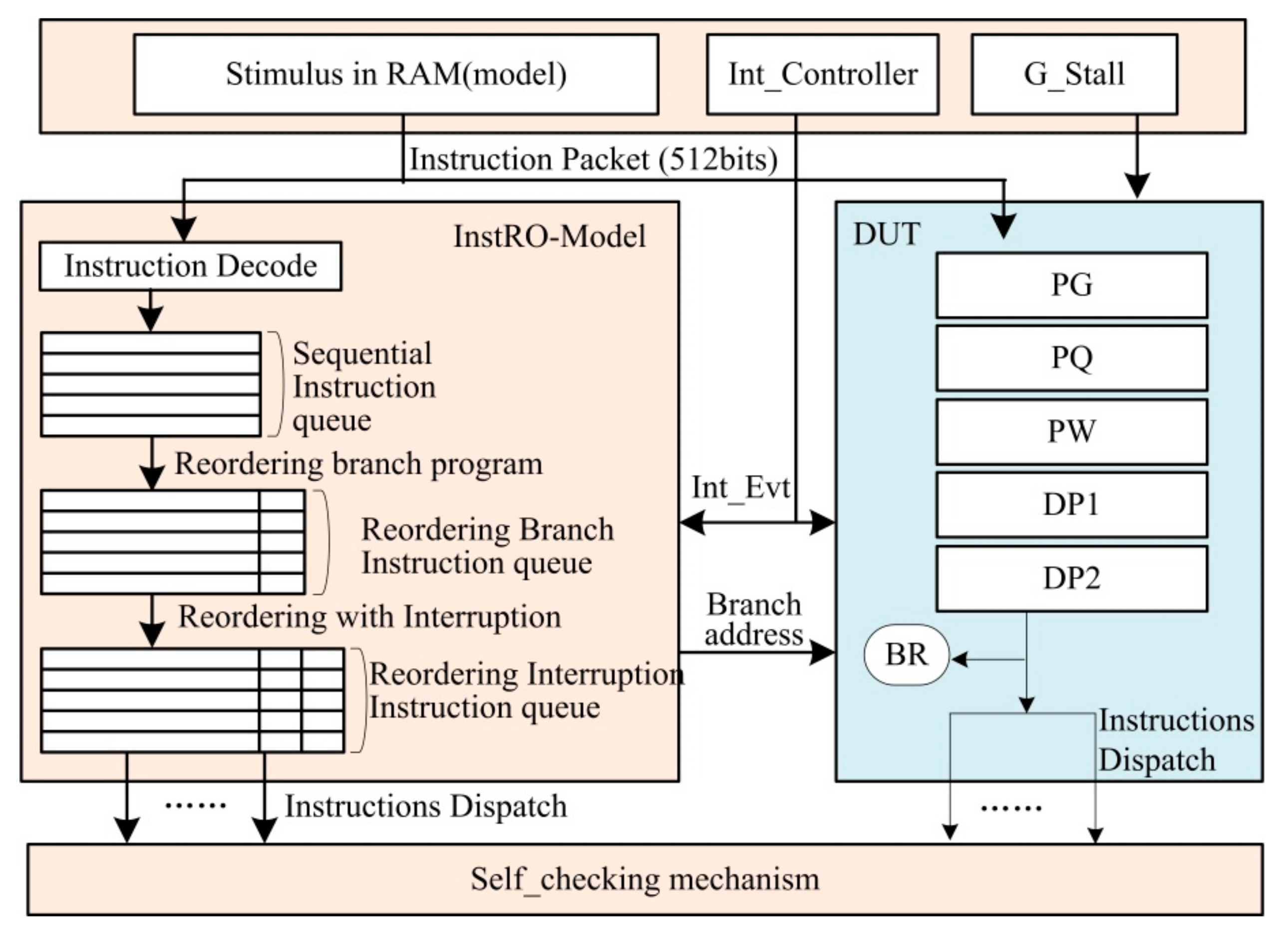
  • Verification of complex protocols: As shown in Figure 2, complex communication occurs between instruction pipelines, which include both control signals and data streams (such as 512-bit FP). When encountering branches and interruptions, it is difficult to traverse the complex states and protocols between pipelines through simple simulation-based verification, and it is also difficult to construct a suitable constraint for a single module (such as BR, PG, DP1, etc.) through formal verification. In addition, whether through simulation verification or formal verification, it is also very difficult to analyze the verification results of the complex control pipeline.
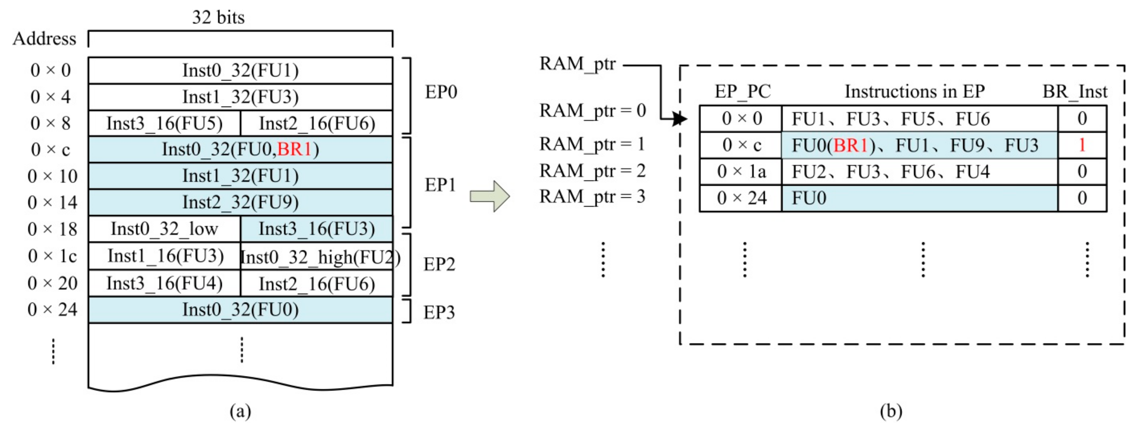
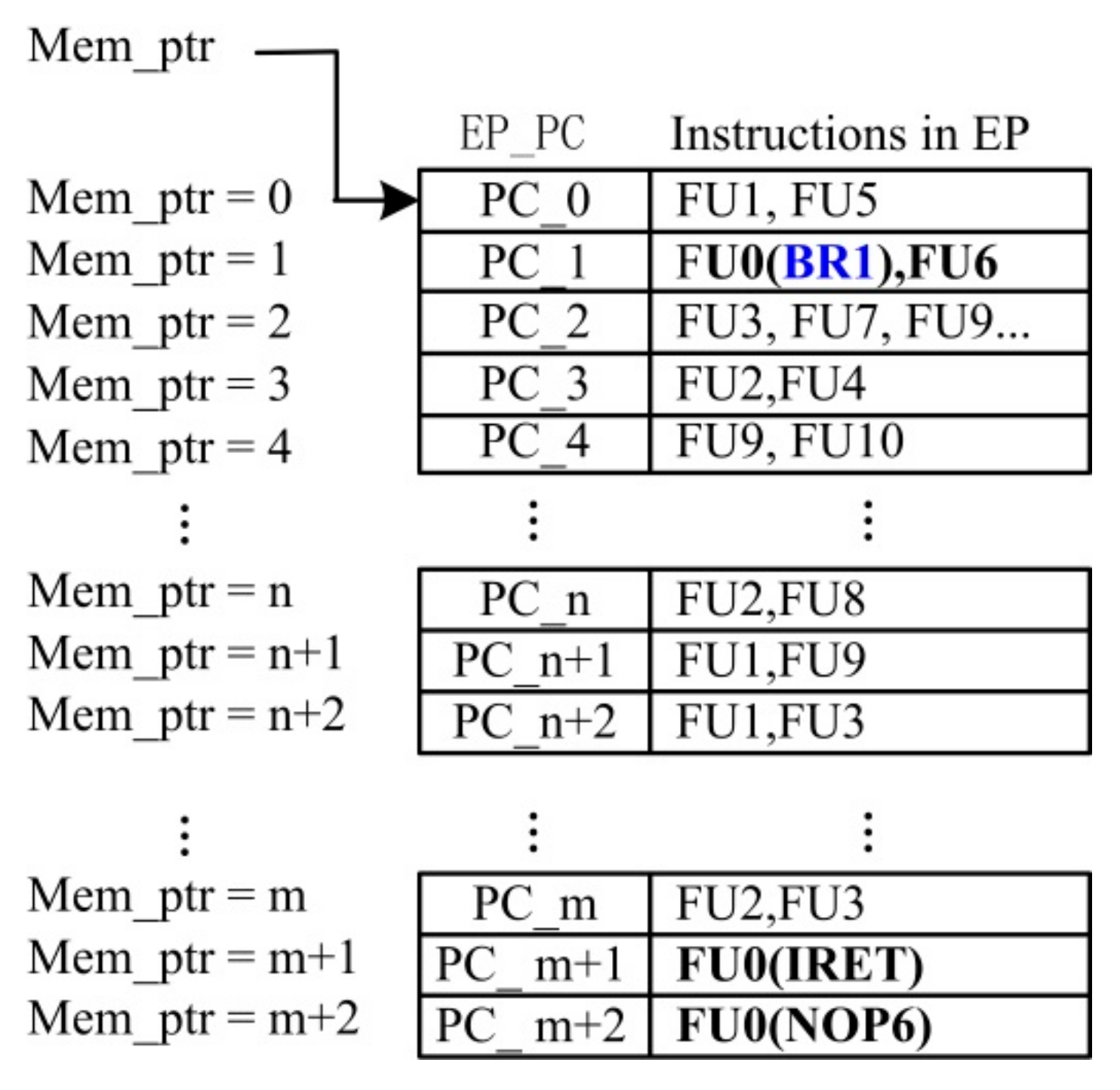
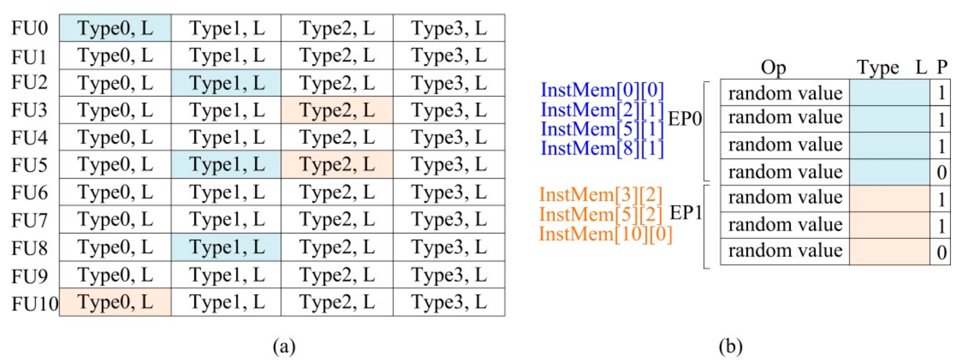
  • Traversal verification of EP parallelism: The instruction format of FT-xDSP is illustrated in Figure 3. As the figure shows, the instructions are closely arranged in PM. Instructions that can be issued in parallel in a single clock cycle are referred to as an execution package (EP). In Figure 4, EP0 can be seen to contain two 32-bit instructions and two 16-bit instructions, while EP1 contains one 32-bit instruction and one 16-bit instruction. This tight arrangement can easily cause an instruction (or an EP) to be located on the boundary of two FPs (aligned according to 512 bit).
In a user program, an EP may contain 1 to 11 instructions of different FUs. The instructions of each FU have at least three types of encoding; thus, the parallelism verification for an EP includes at least i = 1 11 3 i A 11 i cases. It should also be considered that some FUs contain both 16-bit and 32-bit length instructions. When an EP crosses the boundary of two instruction packets, it is necessary to splice the two instruction packets and then dispatch cross-boundary EP instructions. The processing of the cross-boundary EP also becomes more complicated when there are complex branches and interrupts in the pipeline.
  • Program execution sequence verification: There are three types of program execution sequence functional units in FT-xDSP: sequence, branch jump, and interrupt response. Figure 5 presents a schematic diagram of the corresponding program flow. Here, Figure 5a is the sequence Execute the program; the program does not contain a branch instruction (SBR) and no interrupt event occurs. Figure 5b is a branch jump program, and EP2 contains a conditional branch instruction (the branch instruction has six delay slots). If the branch condition is true, after six branch delay slots, the program jumps to the branch target address (BRT; the example in the figure is EP1). If the branch condition is false, the program will continue to execute downward from EP9. Figure 5c is the interrupt response program: when an interrupt event occurs during the execution of the main program, the currently executing program is interrupted and jumps to the interrupt service program (Int_EPx). Until the interrupt transaction is processed, the program returns to the place at which the main program was interrupted to continue execution. In the verification of the program execution sequence, the branch delay slot processing, branch target EP cross-boundary processing, interrupt address preservation, pipeline emptying, and interrupt return address processing are all difficult points of verification, and are also the points most prone to design bugs in DSP chips. In particular, when the frequency of branches and interrupts is high and there are a large number of cross-boundary EPs, not only does the stimulus structure become complicated, but the analysis of the instruction pipeline execution result also becomes very time-consuming and labor-intensive.
In summary, the automatic verification method of IPCU needs to achieve the following:
  • Build a high-level reference model by means of a reasonable level and function division. This model has a simple input–output relationship, which avoids the need to analyze complex protocols between pipelines and can quickly and accurately obtain the correct results of random test incentives;
  • Automatically generate EP parallelism-configurable random instruction test stimuli, and can construct a legal branch program flow and interrupt the program flow via adding legal branch instructions to EP and inserting interrupt events into program flow;
  • Automatically compare results and collect the coverage.

3.1.3. Instruction Reordering (InstRO) Strategy

Different from traditional verification methods, which pay too much attention to the protocol between modules, this paper regards the instruction pipeline of FT-xDSP as a whole. Once the complex internal protocol is ignored, a simple and symmetrical relationship between input and output can be obtained: the input stimulus comprises the instructions in the PM, as well as the global control signal and interrupt control signal, while the output result comprises the instructions dispatched to each functional unit. Regardless of protocol verification, parallelism verification, or program execution sequence verification, the content of verification is to realize certain functions by constructing input instructions, then to analyze the results by detecting the instructions issued by the pipeline. Therefore, an InstRO strategy for IPCU verification is proposed to proceed as follows: decode the input test instruction; model the behavior of the sequential execution program, branch execution program, and interrupt handler in the program execution, and reorder the input program; generate an instruction execution queue that is the same as the actual execution trajectory, such that the generated execution queue is the standard test result. The automatic comparison with the DUT result is realized through assertion, thereby greatly improving the verification efficiency.

3.2. Reference Model Based on Instruction Reordering Strategy (InstRO-Model)

The instruction reordering reference model (InstRO-Model) proposed in this paper is illustrated in Figure 6. First, without considering branch and interrupt processing, the InstRO-Model decodes the input test program to generate a sequential instruction queue. Second, without considering interrupt events, the branch instructions in the program are parsed and a reordered branch instruction queue is generated. Subsequently, after considering the interrupt event, control of the interrupt response and interrupt return is added to the model, and the branch instruction queue is reordered in time according to the program’s actual running sequence. Finally, an interrupt instruction queue is generated that supports branch and interrupt processing—the InstRO-Model’s standard result queue. Here, the generation of the branch/interrupt address needs to be generated in a constrained random method in the process of program flow processing to ensure its legality (e.g., it cannot jump to a non-existing address). In this section, the implementation methods of several important components of the InstRO-Model will be introduced.

3.2.1. Instruction Decoding

As shown in Figure 7a, the test stimulus is stored in the SRAM model. According to the P, L and Type fields of the instruction, the InstRO-Model decodes the instructions in the instruction packet in order (from low to high). The decoded EP address EP_PC and the functional unit instruction FUx contained in the EP are stored in a sequential instruction queue, and each EP is marked as to whether it contains a branch instruction, as shown in Figure 7b. Among them, x in FUx is the function unit label (0–10), EP_PC is the PC value in the SRAM where the EP is located, and RAM_ptr is the read pointer of the instruction queue, indicating the absolute position of the current EP in the SRAM. When the EP pointed to by a RAM_ptr contains a branch instruction (such as BR1, belonging to the FU0 functional unit), then BR_Inst is marked as 1 (see the corresponding line of Figure 7b).

3.2.2. Branch Control

After decoding the test instruction packet to obtain the instruction queue shown in Figure 7b, branch instruction processing is performed on the EP marked as containing a branch instruction, as shown in Figure 8. On the basis of the sequential instruction queue, a branch control queue is added (Figure 8b); the branch control queue and the sequence queue share a pointer RAM_ptr. The branch control queue contains two columns: the branch target address pointer (BRT_ptr) and the branch jump count (cnt). The main elements of processing branch program are as follows:
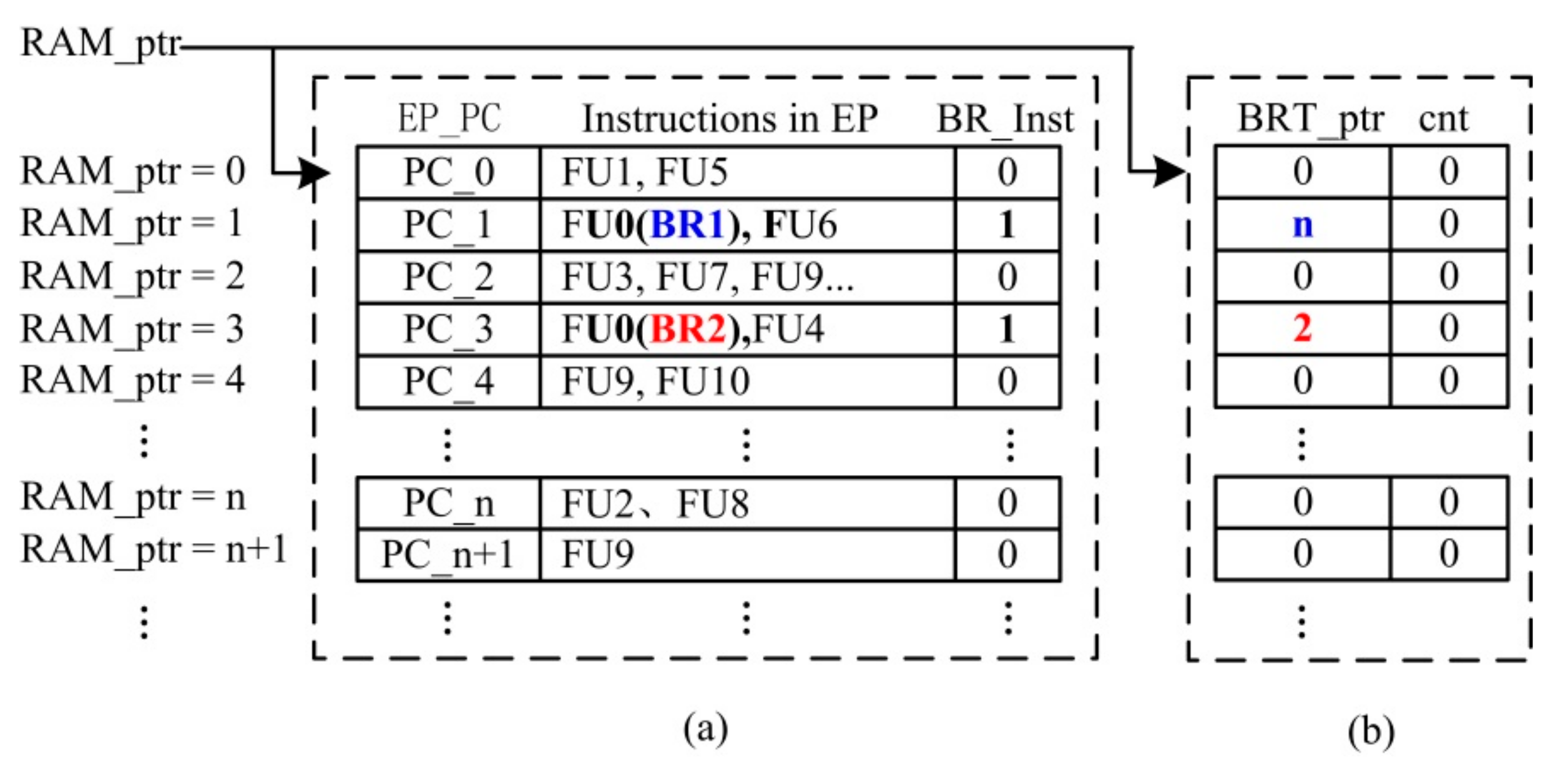
  • Branch target address (BRT) generation. In the DUT, the branch target address of the branch instruction is calculated by the OP field of the branch instruction, or determined by the value in the register specified by the OP field. In the InstRO-Model, the OP field of branch instruction code is randomly generated; accordingly, in order to both ensure the legitimacy of the branch target address and reduce the difficulty of verification, the branch target address is randomly generated in all valid EP_PC. Moreover, at the top level of the DUT Bypass, the branch target address is input to the fetch module, so that the branch target address of the DUT is consistent with that in InstRO-Model. That is, in the sequential instruction queue, when a branch instruction (BR_Inst is 1) occurs in the EP pointed to by a RAM_ptr, an EP_PC is randomly selected as the branch target BRT in the sequential instruction queue. The RAM_ptr corresponding to this EP_PC is then saved to the BR_ptr of the line where the branch instruction is located. For example, in Figure 8a, the BRTs of the two branch instructions of BR1 and BR2 are PC_n and PC_2, respectively. The corresponding RAM_ptrs (n and 2) are then recorded in the respective BRT_ptrs.
  • Branch EP reordering. Based on BRInst and BRT_ptr in Figure 8, InstRO-Model reorders the test program and writes it into a new queue according to the execution order of the execution branch. As shown in Figure 9, the program runs until it reaches the branch instruction BR1. After six delay slots, the program jumps to the random branch target address PC_n of BR1 to continue execution. Subsequently, the program runs to the branch instruction BR2; after six delay slots, the program jumps to the random branch target address PC_2 of BR2 to continue execution. After the branch program pipeline is reordered, the branch control processing queue is also reordered. The new queue pointer is DP_ptr, which represents the actual dispatching order of the DUT. The reordered instruction queue is the standard instruction dispatch result queue of the branch program.
  • Branch jump count. In Figure 9, the branch instruction BR2 constructs a loop program: PC_2–PC_9. If the branch jump is not constrained then, in this test stimulus, the entire test process will involve executing this cycle, resulting in a large number of repeated verifications while also preventing other randomly generated EPs from being effectively verified. Therefore, the count (cnt) of branch jumps is added to Figure 9b. Here, cnt accumulates the number of dispatches of the EP containing the branch instruction. The maximum threshold of cnt (cnt_th) is set in the random stimulus constraint, and the branch instruction is executed only when cnt is less than cnt_th. Assuming that the condition of the execution of the branch instruction is BR_Valid, the condition of the branch jump is as follows:
BR_Valid = (BR_Inst = 1) & (cnt < cnt_th).
For example, if cnt_th = 10, then when the cnt of the line corresponding to BR2 is 10, the branch instruction BR2 will no longer execute the jump, and the pipeline will be executed sequentially.
In the DUT, BR_Valid enters the PG station as the output of the BR unit, and is used as the jump condition of the branch instruction to determine whether the PG needs to fetch the branch address. This prevents the program from entering an infinite loop while simultaneously ensuring the efficiency of the random stimuli.

3.2.3. Processing of Interrupt Event

In the InstRO-Model, a reordered interrupt execution queue is generated after both branch processing and interrupt events have been considered. In practical applications, a variety of interrupt events can occur in the test program, and different interrupt events have different interrupt programs. In the functional verification of the IPCU, the specific function of the interrupt event is not considered. Therefore, in the InstRO-Model, all interrupts use the same interrupt program, and the interrupt program is placed in a specific address at the very end of the test stimulus. As shown in Figure 10. at the end of a test program, RAM_ptr = m, an interrupt service program is added containing three instructions (this number can be increased). Among them, IRET is the interrupt return instruction, while NOP6 is the idling instruction used to fill the six delay slots of IRET. After parsing the test program in Figure 10 and generating a reordering branch instruction queue, an interrupt processing queue is added, as shown in Figure 11b. When a row in the queue is randomly marked as 1, this indicates that an interrupt event occurs when the EP of the current row is executed. The interrupt event triggers the operation of clearing the pipeline, the EP of this line is not actually executed, and this line is saved as the interrupt return address pointer Ret_ptr to BR_ptr in Figure 11a.
The reordering method of the interrupt instruction queue is as follows:
When the program runs until it reaches EP (PC_n+1) where Int_Evt is 1, the current program stops executing, clears all instructions in the instruction pipeline, and writes RAM_ptr = n + 1 as the interrupt return address pointer Ret_ptr into the BR_ptr of the IRET instruction. The program then jumps to the interrupt service program at the end of the stimulus (RAM_ptr = m). After processing the interrupt program at RAM_ptr = m + 1, the interrupt return instruction IRET (with six delay slots) is executed, after which the program returns to the saved interrupt return address Ret_ptr (RAM_ptr = n + 1) to continue executing the main program. Note that, to ensure that the main program can be returned correctly after each interrupt event, the cnt of the IRET instruction is always 0. The instruction queue in Figure 11 is the final result queue of InstRO-Model, which is used to compare the results with the DUT.

3.3. Automatic Generation of Stimulus

In the InstRO-Model, the stimulus of IPCU includes three parts: the instruction code, the fetch address (including the branch jump target address, the interrupt program entry address and the interrupt return address), and the global stall signal.

3.3.1. Instruction Code Generation and Parallelism Configuration

To ensure that the EP is legal and effective, the instruction code generation adopts the constrained random generation method [10]. The process, illustrated in Figure 12, establishes a valid set of instructions InstMem for 11 functional units (FU0–FU10); that is, all legal combinations of Type and L contained in each functional unit. When randomly generating the instruction EP, P functional units are randomly selected according to the limited parallelism P, while a set of valid Type/L combinations InstMem[i][j] (i < 10, J < 4) are randomly selected among the P functional units, spliced with the completely random value Op, and finally arranged tightly to form an EP. The above process is then repeated, and the generated Eps are arranged in sequence in the SRAM model. The instructions in the SRAM are the stimuli of the InstRO-Model and DUT. The generation process of EP0 with parallelism 4 and EP1 with parallelism 3 is presented in Figure 12.
The parallelism and instruction length in EP can be directionally configured, and the pseudocode of the configuration algorithm is as presented below. A random EP with a parallelism of 5–11 is implemented in Table 2. The number of 32-bit instructions in each EP is 4–11. By modifying the parameters of line1–line3, random instruction generation for a specific parallelism range can be realized.

3.3.2. Branch/Interrupt Address Generation

In simulation-based verification, the branch address and interrupt address are generated by the compiler translation [11], and the interrupt return address is recorded by the hardware. In the InstRO-Model, these addresses need to be non-completely random. The mechanism for generating branch and interrupt addresses is as outlined in Section 3.2.2 and Section 3.2.3. Directable non-completely branch address generation is described in this subsection. As shown in Figure 13a, if there is a branch instruction BR1 at the beginning of the test program, and the branch target address ptr_end is at the end of the generated test stimulus, then this random test ends after several instructions have been executed. This random test stimulus is accordingly not helpful for verification.
To avoid this situation, the branch target address of the branch instruction must not deviate too far from the branch instruction. It also must be able to branch both down and up. Assuming that the RAM_ptr of the current branch instruction is BR_ptr, the BRT_ptr can have multiple constraints, as shown in Figure 13. Combined with the branch count (cnt) in the InstRO-Model, the test efficiency of random test excitation is significantly improved.

3.3.3. Generation of Global Control Signal

Although G_Stall will cause a global stalling of the instruction pipeline in DUT, this will not affect the instruction dispatch order. Thus, the global pipeline stall signal G_Stall in this paper can be randomly generated at any time during the verification, and G_Stall has no effect on the InstRO-Model.

3.4. Automatic Results Comparison and Coverage Collection

The results of the InstRO-Model and DUT are automatically compared and analyzed, and because of that the input and output of the InstRO-Model and DUT are symmetrical. This section introduces the method of automatic results comparison used in the InstRO-Model based on the random test stimulus with interruption in Section 3.2.3.
After the random test program is input to the DUT, the output of the DUT is shown in Figure 14; here, FUx_Inst and DP_PC are the EP and its first address output by the DUT in each clock cycle, respectively. The shaded part in FUx_Inst indicates that the current clock cycle dispatches an instruction. When Int_Evt is 1, the executing EP (at PC_n+1) is invalidated, and the program then jumps to PC_m to execute the interrupt service program. After the interrupt transaction is completed, the DUT returns to the interrupted PC_n+1 to continue executing the main program. When a global pause occurs (G_Stall = 1), all instruction dispatches output by the DUT are suspended.
After the random test program is input into the InstRO-Model, a standard result queue sorted according to the order of instruction dispatch is obtained; that is, the reordered interrupt queue in Figure 11a. Because the DUT will stop instruction dispatch when the global pause is in effect, G_Stall also needs to be considered when comparing the results. The automatic comparison method of the results in this paper is as follows: when it is detected that there is no G_Stall at the top level of the DUT, the standard result queue read pointer DP_ptr begins to increment from 0 to read the standard results and monitor whether the running results of the DUT are consistent with the result queue through SVA assertions [12]; when G_Stall = 1, the result queue read pointer DP_ptr remains unchanged. SVA assertion detection works without G_Stall. Table 3 presents some results comparison implementation methods based on SVA; here, ResultQueue_PC is the address of the EP in the standard result queue, while ResultQueue_FU is the EP in the standard result queue. When the result comparison fails, the time and error type are printed, and the corresponding stimulus is saved for debugging and regression verification.
A large number of functional coverage points are added to the InstRO-Model, such that the coverage rate and coverage times of DUTs can be counted. Table 4 presents some examples of functional coverage points.

4. Experiments and Result Analysis

In this paper, the Verilog/System Verilog language [32,33] was used to design and implement an automatic verification platform for IPCU based on the InstRO-Model. Based on the Iverilog simulation platform, a large number of simulations were performed, and the coverage information was recorded. The experiments in this chapter analyze the verification efficiency of the InstRO-Model in terms of configurable directed random constraints, code coverage, simulation time, and portability.

4.1. Configurable Oriented Random Constraints

Once the constrained random stimuli are generated, the efficiency with which these stimuli are utilized directly affects the verification efficiency. To address this problem, in the above chapters, this paper proposes a method of directionally configurable instruction parallelism and constraint parameters such as the branch target address range. During the experiment, by detecting the triggering of relevant assertions in the runtime of the stimuli, the utilization rate of the stimuli was evaluated and adjusted, and it was accordingly determined whether the stimulus generation met the verification expectation.

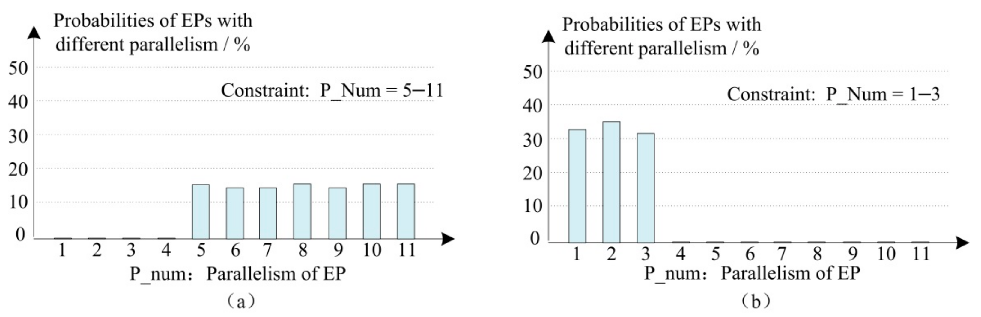
4.1.1. EP Parallelism Configuration

In the experiment, the number of instructions in EP was counted via assertion. According to the number of times that the assertion was triggered, the distribution of EPs with different parallelism in verification could be clearly obtained. Therefore, the configuration of test stimulus parameters could be adjusted to avoid the situation of obtaining dense coverage of one function point and little-to-no coverage of other function points. As shown in Figure 15a,b, the EP parallelism was configured as 5–11 and 1–3, respectively, to generate targeted directional test stimuli. The experimental results proved that the degree of EP parallelism corresponded to the excitation constraint in the test excitation.

4.1.2. Branch Target Address Range Configuration

In the same way, in Figure 16a, when BRT_ptr is an unconstrained random number, the branch instruction that is actually executed during program execution only occupies 48% of all branch instructions (branch cnt is not 0), while unexecuted branch instructions account for 52%. This ratio shows that the test stimulus generated by the unconstrained random BRT_ptr is inefficient, and more than half of the instruction packets are not contained in the actual program execution trajectory. We then adjusted the random constraint of BRT_ptr, as shown in Figure 16b, and limited BRT_ptr to the range of 10 offsets before and after the current branch instruction BR. At this time, it could be seen from the assertion trigger count that 95% of the branch instructions were executed, with only around 5% of instructions not being executed, which is acceptable in random tests with branches.

4.2. Coverage Assessment

Total coverage includes both code coverage and functional coverage. In code coverage, block coverage generally requires 100% coverage, while expression coverage typically requires over 95%. Table 5 lists the coverage of each module of the IPCU when different verification methods are used. The verification of the random stimulus method based on InstRO-Model is slightly insufficient in the BR unit; this is because the BR unit is a pipeline control processing unit that predominantly processes various pipeline control instructions. The simulation-based verification can easily achieve the verification of all valid instructions through manual assembly. In the random stimuli of the InstRO-Model, the opcode field of the BR instruction is randomly generated, and it is difficult to traverse all combinations of multi-bit wide data opcodes for random generation. Compared with the fetch unit, a large number of randomly generated branch instructions and interrupt events can construct a complex pipeline state, which is more advantageous for the verification of complex pipeline protocols. In the end, the two verification methods complement each other, so that the coverage of the DUT meets the required standard. The block coverage rates of the three sub-modules of IPCU all reached 100%, and the expression coverage rates were 96.3%, 99.5%, and 100%, respectively (the remaining uncovered code was related to an aspect of testability design and was not considered in the code coverage). As can be seen from the comparison of the three sets of coverage data, the random verification method based on InstRO-Model was effective and comprehensive for the function points of IPCU that were difficult to verify via manual compilation. The code coverage achieved according to the method of the InstRO-Model was higher than that in other literatures [24,37].
The functional coverage in this paper consists of two parts. The first is the functional point verification statistics based on the functional verification document and simulation verification in the early stage of verification. Second, in the verification based on the InstRO-Model in the later verification stage, SystemVerilog is used to obtain the coverage point statistics. The two finally achieve full coverage of all function points.

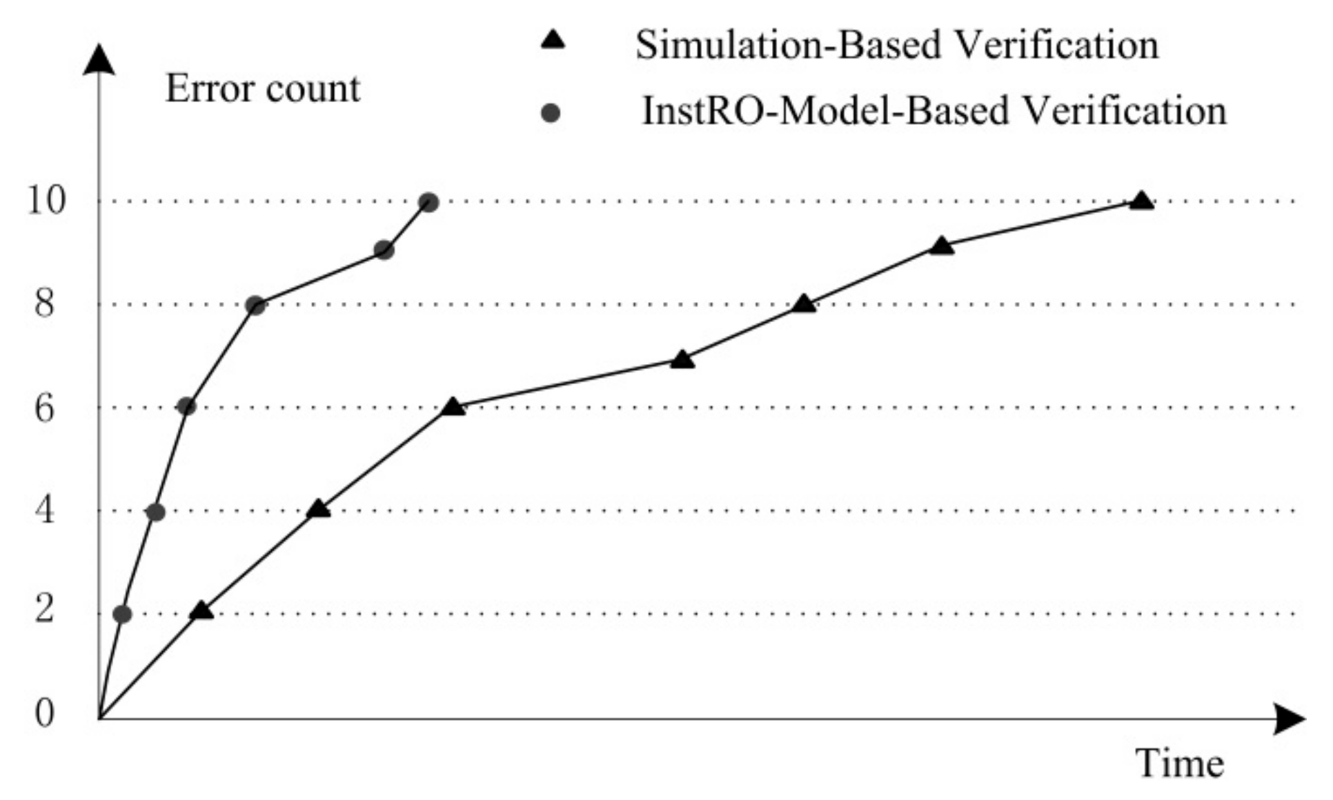
4.3. Simulation Time Analysis

In FT_xDSP, traditional simulation verification and InstRO-Model random verification contribute to the IPCU verification, as shown in Figure 17. Early in verification, traditional functional verification can quickly identify simple errors in the design. However, in the middle and late stages of verification, the efficiency of traditional simulation verification begins to decline. After adding InstRO-Model random verification at time t of the verification cycle, the verification benefits from the quick and iterative generation of random stimuli through advanced scripts, as well as the fact that the results of various complex random stimuli can be automatically compared and analyzed. Therefore, more errors in the dead zone of simulation verification are quickly exposed, which speeds up verification convergence.
At the same time, in order to evaluate the verification efficiency of simulation verification and InstRO-Model random verification under the same conditions, 10 errors found by simulation verification were artificially inserted into the previously verified mature IPCU. Using the configurable random constraints in the InstRO-Model random verification, dense random verification was performed on these 10 errors in a targeted manner. As can be seen from Figure 18, the experimental results showed that, compared with the time of simulation verification (this time was an approximate time), under the premise that there may have been problems with a specific function point, a large number of constrained random excitations were carried out for this function point. Errors can thus be exposed quickly. InstRO-Model stochastic verification has advantages over traditional simulation verification in terms of overall simulation time; this can compensate for the time it spends on model building and constrained random stimulus generation.

4.4. Portability Analysis

Verification based on the InstRO-Model has obvious advantages in terms of overall simulation time. Thus, it is very important to reduce the development time of the InstRO-Model stochastic verification platform. The InstRO-Model verification method has high portability, as outlined below:
  • The processing of the program by the instruction pipeline in the general VLIW DSP can be summarized as sequential execution, branch jump, and interrupt processing. The structure of the InstRO-Model is accordingly suitable for most general-purpose DSPs;
  • The InstRO-Model verification method has a higher level of architecture, and moreover does not involve the results of specific instruction execution (such as multiplication, floating-point operations, etc.). In the VLIW DSP structure, regardless of whether or not the internal protocol of the instruction pipeline is the same, its input signals are still instruction codes, branch or interrupt addresses, and global control signals. Therefore, when generating random test stimuli for IPCU of different processors, it is only necessary to make some changes for the difference of functional unit FUx, instruction Type/L/P, etc. By modifying the relevant information, the directional random generation of the input test stimuli can be completed.
  • Even if different processors have different instruction sets, the output signal of the instruction pipeline also contains the instructions that are sent to each functional unit [34,35,37,38]. The result comparison method can also be personalized on the basis of the InstRO-Model verification method.

5. Conclusions

This paper proposes a random verification method based on the InstRO-Model for those function points that are difficult to verify via simulation-based verification methods in the IPCU of high-performance FT-xDSP. This method first regards the IPCU as a whole, ignoring its internal complex logic, and builds a high-level abstract model based on the instruction reordering strategy according to its symmetry of input and output. Second, according to the input characteristics of the IPCU, random test stimuli with constraints are automatically generated, and the directional intensive testing of specific function points is realized by directionally adjusting the configuration parameters of the test stimuli. Finally, the results of the InstRO-Model and DUT are automatically compared and analyzed, and because of that the input and output of InstRO-Model and DUT are symmetrical. Experiments and practical application results show that this method can quickly generate a large number of configurable directional random stimuli, which greatly improves the verification efficiency. In addition, the method has high portability across different chip designs, and can be applied to other DSP processor chips through personalized transformation, reducing the verification cost of its instruction pipeline.

Author Contributions

Conceptualization, H.W. and S.L.; methodology, H.W.; software, S.L. and H.W.; validation, H.W. and L.Z.; formal analysis, H.W.; writing, H.W.; project administration, S.L.; funding acquisition, S.L. All authors have read and agreed to the published version of the manuscript.

Funding

This research was supported by the National Defense Science and Technology Key Laboratory of Parallel and Distributed Processing of China under project No.WDZC20205500111: Research on Accelerator Architecture for Next Generation High Performance Computing.

Institutional Review Board Statement

Not applicable.

Informed Consent Statement

Not applicable.

Data Availability Statement

Not applicable.

Conflicts of Interest

The authors declare no conflict of interest.

References

  1. Hegde, K.; Yu, J.; Agrawal, R.; Yan, M.; Fletcher, C. UCNN: Exploiting computational reuse in deep neural networks via weight repetition. In Proceedings of the 45th Annual International Symposium on Computer Architecture (ISCA), Los Angeles, CA, USA, 2–6 June 2018; pp. 674–687. [Google Scholar]
  2. Park, E.; Kim, D.; Yoo, S. Energy-Efficient Neural Network Accelerator Based on Outlier-Aware Low-Precision Computation. In Proceedings of the 45th Annual International Symposium on Computer Architecture (ISCA), Los Angeles, CA, USA, 2–6 June 2018; pp. 688–698. [Google Scholar]
  3. May, C.; Silha, E.; Simpson, R.; Warren, H. The PowerPC Architecture: A Specification for a New Family of RISC Processors; Morgan Kaufmann Publishers Inc.: San Francisco, CA, USA, 1994. [Google Scholar]
  4. Shen, H.H.; Wei, W.L.; Chen, Y.J. A Survey on Coverage Directed Generation Technology. J. Comput.-Aided Des. Comput. Graph. 2009, 21, 419–431. [Google Scholar]
  5. Spear, C.; Tumbush, G. SystemVerilog for Verification; Springer: Berlin/Heidelberg, Germany, 2006. [Google Scholar]
  6. Liu, M. Data Coherence Optimization and Verification Platform Research of DMA Accessing in Multi-Core DSP. Master’s Thesis, National University of Defense Technology, Changsha, China, 2016. [Google Scholar]
  7. Wu, Q.W.; Feng, Y. Research for Constructure and Test Method of the DSP. Comput. Digit. Eng. 2010, 9, 84–87. [Google Scholar]
  8. Hu, W.W.; Chen, Y.J.; Li, L.; Cheng, Q. Linear Time Memory Consistency Verification. IEEE Trans. Comput. 2012, 61, 502–516. [Google Scholar] [CrossRef]
  9. Molina, A.; Cadenas, O. Functional verification: Approaches and challenges. Lat. Am. Appl. Res. 2007, 37, 65–69. [Google Scholar]
  10. Chen, P.H.; Wei, L.H. A Method of Improving DSP Test Coverage Based on ATE. Comput. Sci. Appl. 2021, 11, 1598–1606. [Google Scholar]
  11. Farimah, F.; Prabhat, M. Automated Test Generation for Debugging Multiple Bugs in Arithmetic Circuits. IEEE Trans. Comput. 2019, 68, 182–197. [Google Scholar]
  12. Chen, S.M.; Wang, Y.H.; Liu, S.; Wan, J.H.; Chen, H.Y.; Liu, H.Z.; Zhang, K.; Ning, X. FT-Matrix: A Coordination-Aware Architecture for Signal Processing. IEEE Micro 2014, 34, 64–73. [Google Scholar] [CrossRef]
  13. Sun, J.; Shi, P.F.; Feng, C.Y.; Meng, L.; Zhang, H. Low Power Verification Based on Multi-Cores DSP. Microelectron. Comput. 2015, 12, 116–121. [Google Scholar]
  14. Chen, Y.J.; Li, L.; Chen, T.S.; Li, L.; Wang, L.; Feng, X.X.; Hu, W.W. Program Regularization in Memory Consistency Verification. IEEE Trans. Parallel Distrib. Syst. 2012, 23, 2163–2174. [Google Scholar] [CrossRef]
  15. Feig, R.; Weiss, S. Functional verification of instruction processing units through control flow modeling. Microelectron. J. 2002, 33, 285–299. [Google Scholar] [CrossRef]
  16. Qi, J.Y. A RISC instruction pipeline architecture. Mini-Micro Syst. 1995, 16, 1–5. [Google Scholar]
  17. Jiang, J. Research and Implementation on Instruction Control Pipeline in General-Purpose EPIC Microprocessor. J. Chin. Comput. Syst. 2006, 27, 1661–1664. [Google Scholar]
  18. Sabaghian-Bidgoli, H.; Behnam, P.; Alizadeh, B.; Navabi, Z. Reducing Search Space for Fault Diagnosis: A Probability-Based Scoring Approach. In Proceedings of the IEEE Computer Society Annual Symposium on VLSI (ISVLSI), Bochum, Germany, 3–5 July 2017; pp. 545–550. [Google Scholar]
  19. Akbarpour, B.; Tahar, S. An approach for the formal verification of DSP designs using Theorem proving. IEEE Trans. Comput.-Aided Des. Integr. Circuits Syst. 2006, 25, 1441–1457. [Google Scholar] [CrossRef] [Green Version]
  20. Gu, Y.L.; Xu, W.B. Study on Automatic Test Generation of Digital Circuits Using Particle Swarm Optimization. In Proceedings of the 2011 10th International Symposium on Distributed Computing and Applications to Business, Engineering and Science, Wuxi, China, 14–17 October 2011; pp. 324–328. [Google Scholar]
  21. Cerny, E.; Dudani, S.; Havlicek, J.; Korchemny, D. SVA: The Power of Assertions in SystemVerilog; Springer: Berlin/Heidelberg, Germany, 2011. [Google Scholar]
  22. Fooladi, M.; Kamran, A. Speed-Up in Test Methods Using Probabilistic Merit Indicators. J. Electron. Test. 2020, 36, 285–296. [Google Scholar] [CrossRef]
  23. Aghaei, B. A high fault coverage test approach for communication channels in network on chip. Microelectron. Reliab. 2017, 75, 178–186. [Google Scholar] [CrossRef]
  24. Liu, W.H.; Yu, M.Y.; Wang, J.X. A Graph-model Based Code-coverage-improving Verification Method. Microprocessors 2008, 6, 48–50. [Google Scholar]
  25. Bin, E.; Emek, R.; Shurek, G.; Ziv, A. Using a Constraint Satisfaction Formulation and Solution Techniques for Random Test Program Generation. IBM Syst. J. 2002, 41, 386–402. [Google Scholar] [CrossRef] [Green Version]
  26. Braun, G.; Nohl, A.; Hoffmann, A.; Schliebusch, O.; Leupers, R.; Meyr, H. A Universal Technique for Fast and Flexible Instruction-Set Architecture Simulation. IEEE Trans. Comput.-Aided Des. Integr. Circuits Syst. 2006, 23, 1625–1639. [Google Scholar] [CrossRef]
  27. Tasiran, S.; Batson, B.; Yu, Y. Linking Simulation with Formal Verification at a Higher Level. IEEE Des. Test Comput. Mag. 2004, 21, 472–482. [Google Scholar] [CrossRef]
  28. Zhu, D.L.; Guo, D.Y.; Hu, H. Rapid implementation of instruction-level precision VLIW DSP simulator. Comput. Eng. Des. 2013, 34, 256–261. [Google Scholar]
  29. Monaco, J.; Holloway, D.; Raina, R. Functional verification methodology for the PowerPC 604 microprocessor. In Proceedings of the 33rd Annual Design Automation Conference, Las Vegas, NV, USA, 3–7 June 1996; pp. 319–324. [Google Scholar]
  30. Shen, J.; Abraham, J.; Baker, D.; Hurson, T.; Kinkade, M.; Gervasio, G.; Chu, C.C.; Hu, G. Functional Verification of the Equator MAP1000 Microprocessor. In Proceedings of the 1999 36th Annual Design Automation Conference (DAC), New Orleans, LA, USA, 21–25 June 1999. [Google Scholar]
  31. Foote, T.G.; Hoffman, D.E. Testing the 500-MHz IBM S/390 microprocessor. IEEE Des. Test Comput. Mag. 1998, 15, 83–89. [Google Scholar] [CrossRef]
  32. Bustan, D.; Korchemny, D.; Seligman, E.; Yang, J. SystemVerilog Assertions: Past, Present, and Future SVA Standardization Experience. IEEE Des. Test Comput. 2012, 29, 23–31. [Google Scholar] [CrossRef]
  33. IEEE STD 1800–2009; IEEE Standard for SystemVerilog—Unified Hardware Design, Specification, and Verification Language. IEEE: New York, NY, USA, 2009.
  34. Gong, L.K.; Lu, J.F. Verification-Purpose Operating System for Microprocessor System-Level Functions. IEEE Des. Test Comput. 2010, 27, 76–85. [Google Scholar] [CrossRef]
  35. Hosseini, A.; Mavroidis, D.; Konas, P. Code generation and analysis for the functional verification of microprocessors. In Proceedings of the 33rd Design Automation Conference Proceedings, 1996, Los Angeles, CA, USA, 3–7 June 1996. [Google Scholar]
  36. Duran, C.; Morales, H.; Rojas, C.; Ruospoy, A.; Sanchezy, E.; Roa, E. Simulation and Formal: The Best of Both Domains for Instruction Set Verification of RISC-V Based Processors. In Proceedings of the IEEE International Symposium on Circuits and Systems (ISCAS), Seville, Spain, 12–14 October 2020; pp. 1–4. [Google Scholar]
  37. Bratt, J.P.; Yan-Tek, H.P.; Joshi, C.S.; Nofal, M.R.; Paul, R.; Scanlon, J.T.A.K. Superscalar Microprocessor Instruction Pipeline Including Instruction Dispatch and Release Control. EP0690372 A1, 12 March 2010. [Google Scholar]
  38. Momose, T.; Fujita, A.; Kubo, K. Data Processing System with an Enhanced Instruction Pipeline Control. CA1098214 A1, 24 March 1981. [Google Scholar]
Figure 1. Coverage-driven verification.
Symmetry 14 00646 g001
Figure 2. Instruction pipeline structure of FT-xDSP.
Symmetry 14 00646 g002
Figure 3. Instruction format. P is the parallel bit, indicating whether the next instruction can be dispatched in parallel with the current instruction. L is the length bit, indicating that the instruction length is either 16 bits or 32 bits. Type indicates the functional unit corresponding to the instruction. Op is the opcode of the instruction.
Symmetry 14 00646 g003
Figure 4. Execution package in the fetched package. Different background colors represent different EPs.
Symmetry 14 00646 g004
Figure 5. Three kinds of program execution sequence; (a) is the sequence ‘Execute the program’; (b) is a branch jump program; (c) is the interrupt response program.
Symmetry 14 00646 g005
Figure 6. Modeling of instruction reordering.
Symmetry 14 00646 g006
Figure 7. Sequential instruction queues in the InstRO-Model, Red characters indicate a branch instruction, and different background colors represent different EPs. (a) is instructions in RAM; (b) is sequential instruction queues in the InstRO-Model.
Symmetry 14 00646 g007
Figure 8. Branch test program processing. (a) Sequential instruction queues in the InstRO-Model. (b) Branch control queues.
Symmetry 14 00646 g008
Figure 9. Reordering of Branch EP in the InstRO-Model. (a) Branch EP queues in the InstRO-Model. (b) Branch control queues.
Symmetry 14 00646 g009
Figure 10. Test program with interrupt event.
Symmetry 14 00646 g010
Figure 11. Reordering Interruption EP queues. (a) Interruption EP queues in the InstRO-Model. (b) Interrupt event.
Symmetry 14 00646 g011
Figure 12. Random generation of instructions with constraint. (a) Inst-Memory: all Types for function units. (b) example of EP generation.
Symmetry 14 00646 g012
Figure 13. Non-completely random generation of branch target address. (a) BRT_ptr = $random: when BRT_ptr is close to the end of the program, the test program will immediately jump to the end of the program after executing several cycles; the test stimulus is close to an invalid stimulus. (b) BRT_ptr = BRT_ptr + $random: the branch target range is the address after the current branch instruction. The program only jumps down. (c) BRT_ptr = $random%BRT_ptr: the branch target address range is the address before the current branch instruction, EP0~EPx−1. The program only jumps up. (d) BRT_ptr = {BR_ptr − $random%(2n) + n}: the BRT address range is between n EPs before or after the current branch instruction, EPx−n~EPx+n. The program can jump up or down. The branch offset adjustment is achieved by adjusting the size of n.
Symmetry 14 00646 g013
Figure 14. Debug waveform of Interruption program.
Symmetry 14 00646 g014
Figure 15. Verification with different stimuli generated with different parallelism. (a) P_Num = 5–11, (b) P_Num = 1–3.
Symmetry 14 00646 g015
Figure 16. Verification with different stimuli generated with different branch target address ranges. (a) BRT_ptr is random; (b) BRT_ptr is limited to a range of 10 offsets before and after the current branch instruction BR.
Symmetry 14 00646 g016
Figure 17. Contribution of simulation verification and InstRO-Model-based verification.
Symmetry 14 00646 g017
Figure 18. Comparison of simulation time between simulation verification and InstRO-Model random verification.
Symmetry 14 00646 g018
Table 1. Evaluation of code coverage.
Verification MethodsAdvantageDisadvantageScope of Application
Simulation-based directed
functional verification
Efficient in the initial stage of verificationHard to perform state traversal on the DUT, highly time-consuming, and rarely reusedSimple design [13,14,15]
Formal verification based on random stimulationEasy to perform state traversal on the DUTProblem of exploration space explosionSimple logic [18,19,20]
Verification method based on a reference modelRealize simulation verification or random verificationRealization of the reference model is difficultData-intensive design [6,22,23,24,25] or system-level processors [31,36]
Table 2. Pseudocode for constrained random parallelism instruction packet.
LinePseudocodeDescription
Begin
1: P_min = 5;1: Set the minimum parallelism of EP, assuming it is set to 5.
2: P_max = 11;2: Set the maximum parallelism of EP, assuming it is set to 11.
3: P_min32 = 4;3: Set the minimum parallelism of 32-bit length instructions,
    assuming it is set to 4 (Note: P_min32 ≤ P_min).
4: for(I = 32′h0; I < 15′d524288; I = I + 1)4: After the parameters are set, begin randomly generating 1M EPs.
5:   begin
6:     P_offset = P_max − P_min + 1;6: Calculate the random range of EP parallelism, P_offset = 11 − 5 + 1 = 7.
7:
 
     P_num = P_min
     + {$random}%P_offset;
7: For the current randomly generated EP parallelism,
    assuming $random(seed) is 2022, P_num= 5 + 2022%7 = 11.
8:
 
 
     P_num32 = P_min32
   + {$random}%(P_num − P_min32
   + 1);
8: The number of 32-bit instructions in EP:
    P_num32 = 4 + 2022%(11 − 4 + 1) = 6.
9:     P_num16 =P_num − P_num32;9: The number of 16-bit instructions in EP: P_num16 = 11 − 6 = 5.
10:     Task_Genrate32bitInst (P_num32);10: Generate P_num32 32-bit instructions.
11:     Task_Genrate16bitInst (P_num16);11: Generate P_num16 16-bit instructions.
     End
End
Table 3. Automatic results comparison based on SVA.
LineSVA Assertions
1:assert_DP_PC: assert property (@(posedge clk) disable iff (~rst_n)
if (!G_Stall) ResultQueue_PC [DP_ptr] == DUT.DP_PC);
2:assert_U1_Inst: assert property (@(posedge clk) disable iff (~rst_n)
if (!G_Stall) ResultQueue_FP [DP_ptr] ==
{DUT.FU0_Inst, DUT.FU1_Inst, …, DUT.FU10_Inst});
Table 4. Function coverage points based on SVA.
LineSVA Assertions
1:cover_IH_Flush_U1: cover property (@(posedge clk) disable iff (~rst_n)
if (!G_Stall) FU1_Valid && IH_Flush);
2:cover_IH_Flush_with_GStall: cover property (@(posedge clk) disable iff (~rst_n)
                  IH_Flush && G_Stall);;
Table 5. Evaluation of code coverage.
Unit in IPCUSimulation-Based Coverage (%)InstRO-Model Coverage (%)Total Coverage (%)
BlockExpressionBlockExpressionBlockExpression
Fetch96.582.79992.810096.3
Dispatch10087.410096.210099.5
BR10010096.290.3100100
Publisher’s Note: MDPI stays neutral with regard to jurisdictional claims in published maps and institutional affiliations.

