Article

Engine Knock Sensor Based on Symmetrical Rhomboid Structure-Encapsulated Fiber Bragg Grating

College of Engineering, Northeast Agricultural University, Harbin 150030, China
*
Author to whom correspondence should be addressed.
Symmetry 2022, 14(4), 711; https://doi.org/10.3390/sym14040711
Submission received: 24 February 2022 / Revised: 24 March 2022 / Accepted: 30 March 2022 / Published: 1 April 2022

Abstract

:
Due to the improvement of environmental protection emission standards, new energy vehicles fueled by natural gas and hydrogen green clean energy have developed rapidly. However, knock is one of the most important parameters that must be monitored for the safe operation of natural gas and hydrogen engines, so higher requirements are put forward for the reliability and durability of knock sensors. At present, the common knock sensors are mainly electronic sensors based on magnetostrictive and piezoelectric principles, and the sensing signals are easily interfered by electromagnetic interference during use, which is not conducive to the accurate measurement and control of knock. In this paper, a new resonant knock sensor based on fiber Bragg grating (FBG) is proposed to meet the actual needs of knock monitoring, and the FBG sensor unit is encapsulated with symmetrical rhomboid structure. The natural frequency of rhomboid structure is simulated and analyzed by Ansys software. The natural frequency of rhomboid structure is measured by applying transient impact. The resonance frequency of sensor is analyzed by Matlab software. The theoretical analysis is consistent with the measured value, which verifies the feasibility of the new knock sensor. Compared with the traditional engine knock sensor, this resonant engine knock sensor based on FBG has more advantages in anti-electromagnetic interference and multi-point networking, which provides a new method for knock monitoring of new energy engines.

1. Introduction

Nowadays, people pay increasingly more attention to energy consumption and engine power; therefore, there is increased attention on the improvements to engine efficiency [1,2]. Novel strategies, such as boosting [3,4], high compression ratio [5], downsizing [6], and down-speeding [7], have the capability to greatly improve spark-ignition engine performance and economy. Unfortunately, these factors increase the knocking tendency of the engine. During the engine knocking process, the in-cylinder local pressure is extremely uneven [8]. The violent pressure waves may be amplified by the wave–flame interactions and wall reflections [9], leading to irreversible physical damage to the engine, such as explicit cylinder head erosion, piston ring breakage, piston melting, etc. [10]. Modern on-board, real-time knock control systems require sensors that meet certain requirements, namely, they need to be compact, inexpensive, and easy to install, alongside ensuring a reliable knock detection and its quantification [11]. Therefore, the development of the engine knock sensors with excellent performance has become especially important.
At present, piezoelectric knock sensors are mainly used in most automobiles. Common piezoelectric knock sensors, which are mounted onto an air manifold or cylinder head, can generate an output voltage associated with inadequate combustion of fuel. The engine vibrations are proportional to this output, and by sending this signal to a microprocessor connected to the knock sensor, the engine can adjust the spark timing [12] to avoid knock. The chance of engine knock can also be reduced by water injection [13], fuel enrichment [14], and increasing the fuel octane number [15,16]. Jiang et al. [17,18,19] have applied various methods to study engine knock, and Benjamín et al. [20,21] put forward a new knock recognition method to improve the accuracy of knock detection, but the piezoelectric knock sensor is easily interfered with by electromagnetic field, and the problem of relatively low durability has not been solved. In recent years, some methods [22,23,24] with high precision can detect engine knock, but they have not been applied in practice because of their high cost and low durability. Due to the increasing problem of global warming, industry and research communities are studying alternative fuels [25,26]. Some new energy sources, such as compressed natural gas (CNG) and hydrogen, are used as substitutes for traditional fuels to improve emissions [27]. For these new energy sources, they suitable for higher compression ratio spark-ignition engine operation [28]. The knocking phenomenon is more prominent and severe at low engine speed and high load conditions under a high compression ratio engine operation [29]. In addition, these new energy sources have higher requirements for safety and explosion-proof characteristics of engine knock sensors.
In order to meet these requirements, a knock sensor based on FBG array was developed. Compared with other knock sensors based on cylinder pressure, it is not only less susceptible to electromagnetic interference, but also has lower cost and easier networking. The FBG sensor is attached in series through an optical cable, and the output signal is connected to the demodulation module. The demodulation module includes arrayed waveguide grating (AWG), a super luminescent diode (SLD) light source, multiple photoelectric converters, an advanced RISC machine (ARM) processor, and a controller area network (CAN) bus. The ARM processor provides control instructions for the SLD light source, and the SLD light source provides stable light source for the FBGs through the fiber pigtail. The optical signal carrying the horizontal strain signal output by the fiber pigtail is input into the AWG, and the AWG selects the corresponding channel according to the wavelength range reflected by the optical signal. Through the photoelectric converter devices in the corresponding channel, the electrical signal of knock intensity is converted and sent to the input end of ARM processor. The ARM processor sends the received electrical signal of knock intensity to the electronic control unit (ECU) for real-time processing through the CAN bus. This facilitates the monitoring of the engine knock, enabling both the control of the engine ignition timing and an adjustment of the working state of the engine to eliminate the unwanted detonation. The organization of this work is as follows: Firstly, the principle of the experiment is introduced, and the structure of the sensor is designed based on optical fiber sensor. Then, the natural frequency is simulated by Ansys software. Design experiments, using Matlab software to analyze the natural frequency of the sensor, carry out fast Fourier transform (FFT) on the obtained data, comprehensively analyze its characteristics in time domain and frequency domain, and compare them with theoretical simulation data. Because of the excellent characteristics of FBG, the sensors have been well studied [30,31,32], and the feasibility of the FBG sensor is demonstrated in this paper, and the measurement results are analyzed and discussed.

2. Principles

2.1. Principles of FBG Sensing

For cases when only the change in the stress or strain acts as the external condition, the resulting external force causes the FBG to be stretched in the axial direction. Due to the elastic-optical effect of the FBG, the change in the effective refractive index leads to a modification of the central wavelength of the reflected light [33]. Under the influence of such an effect, the following expression is found:
Δ λ B = 2 Δ n e f f Λ + 2 n e f f Δ Λ ,
where ΔΛ is the periodic change of the FBG, and Δneff is the change in the refractive index of the FBG. The following is also determined:
Δ λ B λ B = ( 1 p e ) Δ ε ,
where pe denotes the effective elasticity coefficient, ε is the strain in the fiber, and λB is the wavelength of the FBG. Equation (2) represents the theoretical formula for FBG strain sensing. Such a sensor converts the change in the strain into a modification of the center wavelength of the FBG that reflects the change of the external stress. Since FBG has the advantages of small size, light weight, anti-electromagnetic interference, etc., it provides an excellent solution to the problem that the piezoelectric ceramics, which act as the sensitive element of the knock sensor, are susceptible to electromagnetic interference [34].

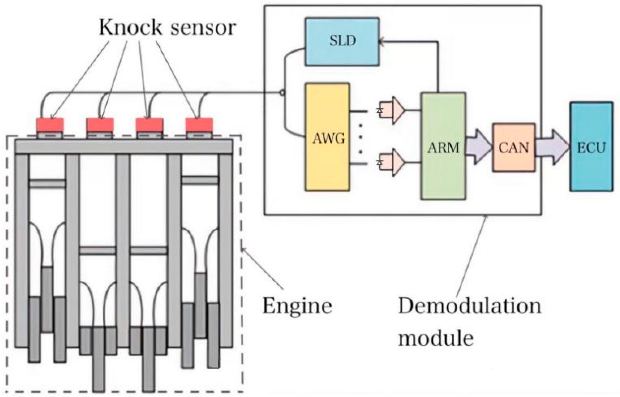
2.2. Knock Sensor Based on Resonance Principle

The knock sensor makes use of the vibrational frequency of the engine during the knocking, which is consistent with the natural frequency of the sensor and results in a resonance. The sensor is used to monitor whether knocking is occurring and inputs the detected signal into the ECU. The latter adjusts the ignition advance angle according to the feedback signal received from the knock sensor [35]. As shown in Figure 1, the real-time monitoring of engine knocking is achieved when structural resonance occurs. This enables the ignition advance angle to be kept at the best position for improved engine performance for avoiding engine knock; this will extend the working lifetime of the engine. The engine vibration curve is obtained by the combustion analyzer. According to the curve in Figure 1, when engine deflagration is occurring, the output signal of the knock sensor will much higher than that in no-deflagration process.
However, most of the sensitive components that are commonly used in resonance piezoelectric deflagration sensors involve piezoelectric ceramics, which are highly susceptible to the electromagnetic interference that affects the accuracy of their measurements. In contrast, we use FBGs to avoid these problems instead of piezoelectric elements, adopting a rhomboid symmetrical structural design.

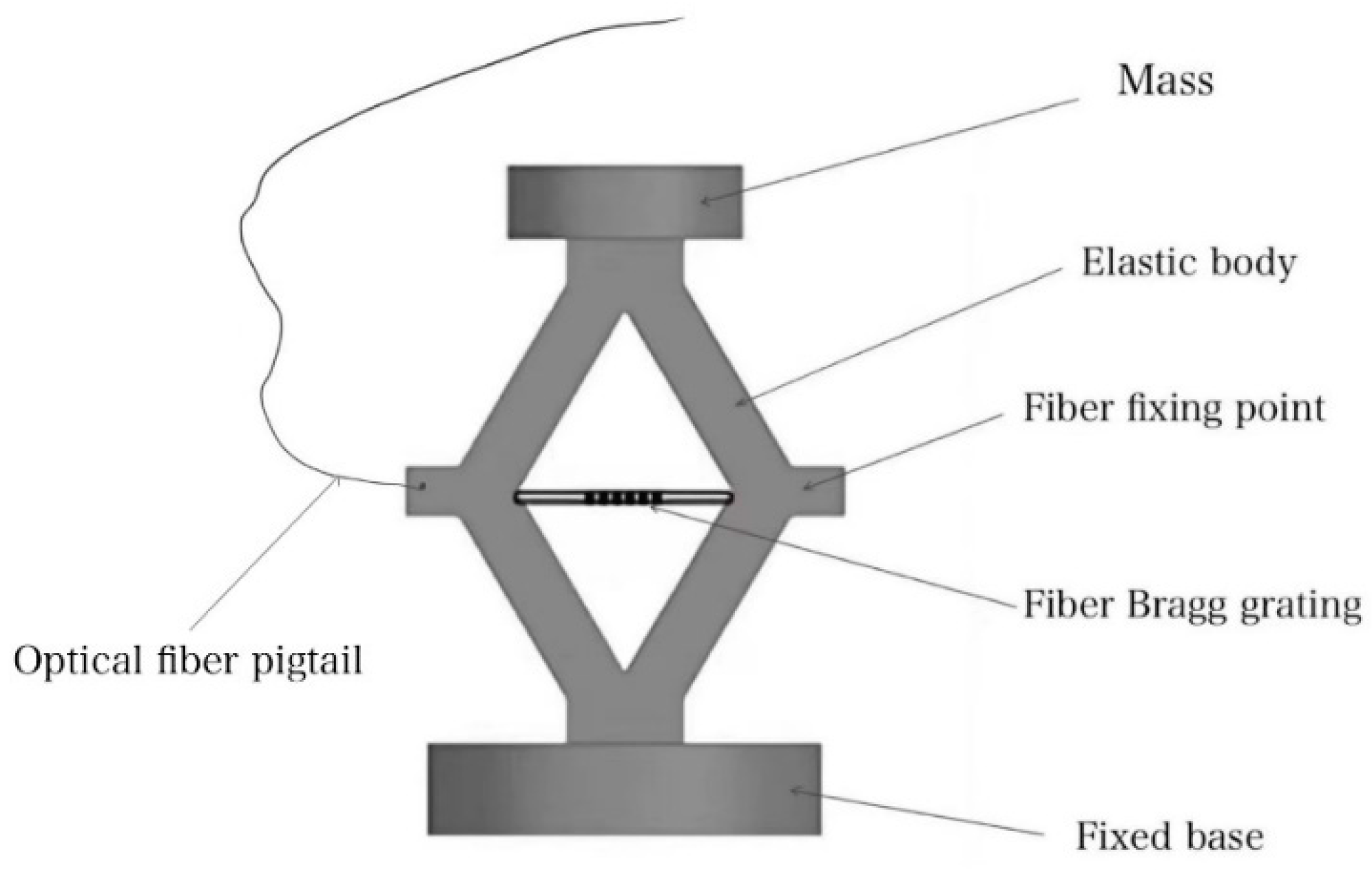
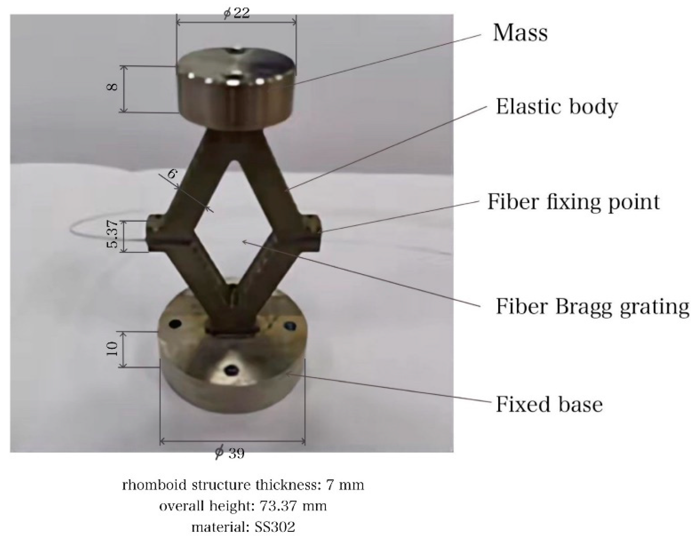
3. Structural Design of Automobile Engine Knock Sensor Based on FBG

The structural design of the automobile engine knock sensor based on FBGs is shown in Figure 2. The elastic body of the rhombus structure is fixed between upper and lower masses, and the FBG is fixed onto a diagonal line of the elastic body of the rhombus structure. When the mass vibrates up and down in the vertical direction, according to the rules of trigonometry, when there is a vibration in the vertical direction, the horizontal direction will also undergo stretching. Therefore, the rhombic structure converts the vertical vibration of the elastic body into a stretching of the FBG in the horizontal direction, which causes a horizontal strain in the FBG and a shift of the central wavelength. The impact of the detonation triggers a resonance in the mechanical second-order system, which is composed of a mass and an elastic body. When a mechanical resonance occurs, there is a dynamic deformation of the rhombic elastic body, and the external force causes the FBG to have tension and compression in the axial direction. The elastic-optical effect of the FBG and the change in the effective refractive index lead to a modification of the central wavelength of the reflected light. The dynamic frequency change of the light reflects when the structural resonance of the mechanical second-order system is caused by engine knocking and, thus, a real-time monitoring system of engine knock can be realized.
During installation, the knock sensor of the FBG array can be fixed at the corresponding position of the engine cylinder via bolts. Due to the low cost and the easy networking of the FBGs, the sensors are connected in a series through an optical cable.
As shown in Figure 3, when the engine is about to knock, the sensor detects the shock and the vibrations from the cylinder, and the output signal is sent to the AWG via a pigtail. The AWG then selects the channel to output, which depends on the wavelength range that is provided by the optical signal. The photoelectric converter outputs an electrical signal to the microprocessor. Next, the microprocessor transmits this signal to the electronic control unit ECU via the CAN bus for real-time processing that delays the ignition advance angle, so that the engine is out of the deflagration zone. As a result, the service lifetime of the engine may be extended. Next, the symmetrical structure is simulated and experimented to verify its feasibility in practical application.

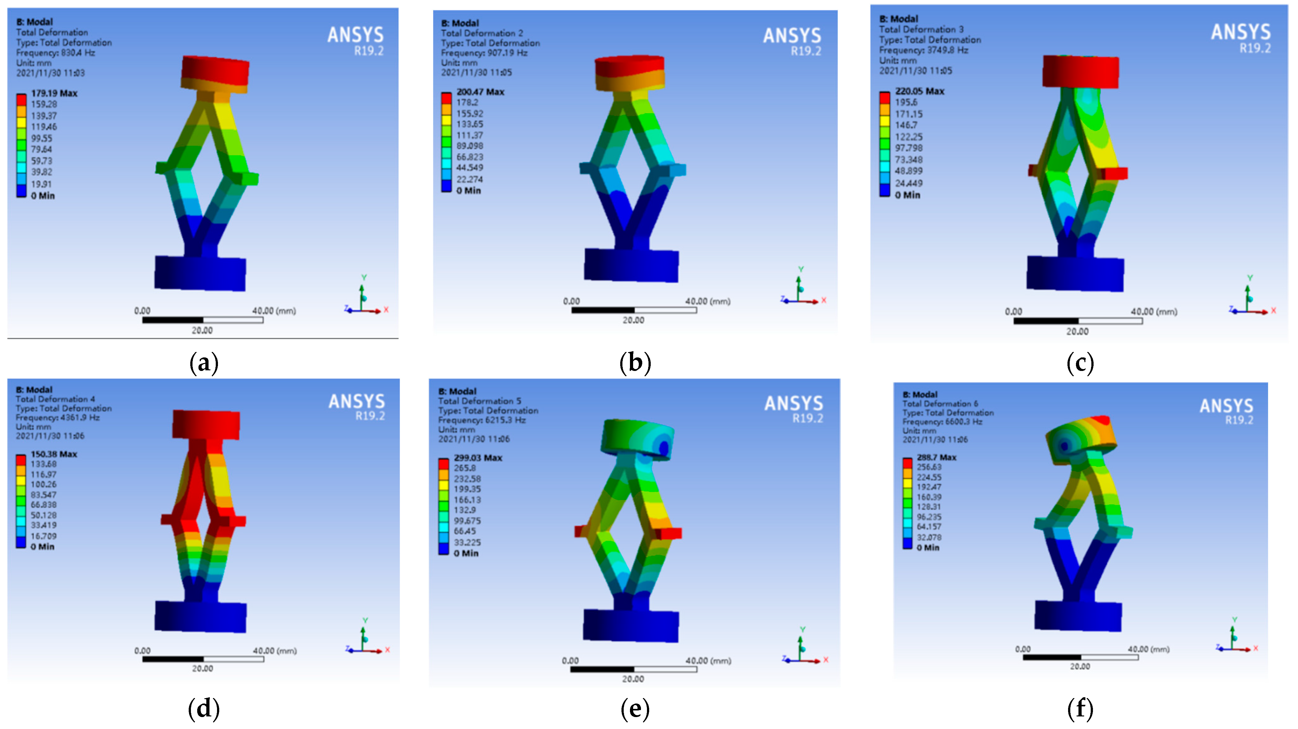
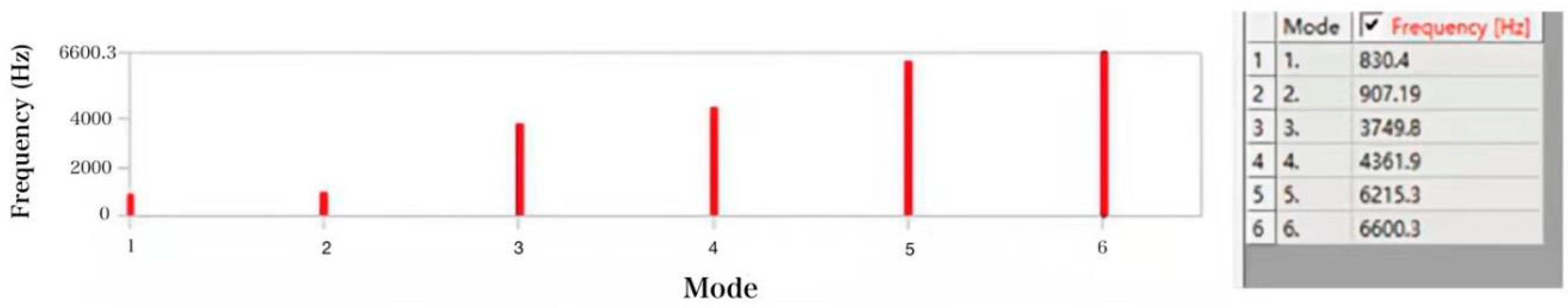
4. ANSYS Simulation of The Natural Frequency

Ansys finite element analysis software is used to simulate the natural frequency of the mechanical structure of the sensor. This is achieved by fixing one end of the mass and applying an impact force onto the other end. Six modes are selected for the analysis, and the vibrational states of each order of the elastic element are obtained; these are shown in Figure 4. With respect to the actual demands of the automobile knock sensor, only the fourth-order mode involves a vertical force acting on the rhomboid-shaped mechanical structure. As shown in Figure 5, the natural frequency of the rhomboid element is calculated via the simulation to be 4361.9 Hz for the fourth mode. The result is that the rhomboid-shaped mechanical structure is horizontally stretched, and the central wavelength of the FBG is shifted. Based on the simulation results, the actual machine part is designed and constructed as shown in Figure 6.

5. Experiment and Analysis

5.1. Design of the Measuring Device for the Resonance Sensor

In this work, the impact method was chosen to measure the natural frequency of the resonant knock sensor. The impact source for the test device is a falling steel ball that is dropped from a certain height, and the impact elastic wave acts on the sensor under test conditions. Due to damping, the excited sensor freely vibrates at its own natural frequency.
Figure 7 shows the system for measuring natural frequency via the free vibrational method. The system includes a steel ball, a resonant knock sensor, a high-speed FBG demodulator, and signal acquisition software. The steel ball freely falls onto the steel plate and produces an instantaneous impact. The resultant shock wave then acts on the resonance knock sensor. The short-term shock pulse of the steel ball contains a frequency component that equals the natural frequency of the resonance sensor. The latter is based on its own inherent frequency and vibration.

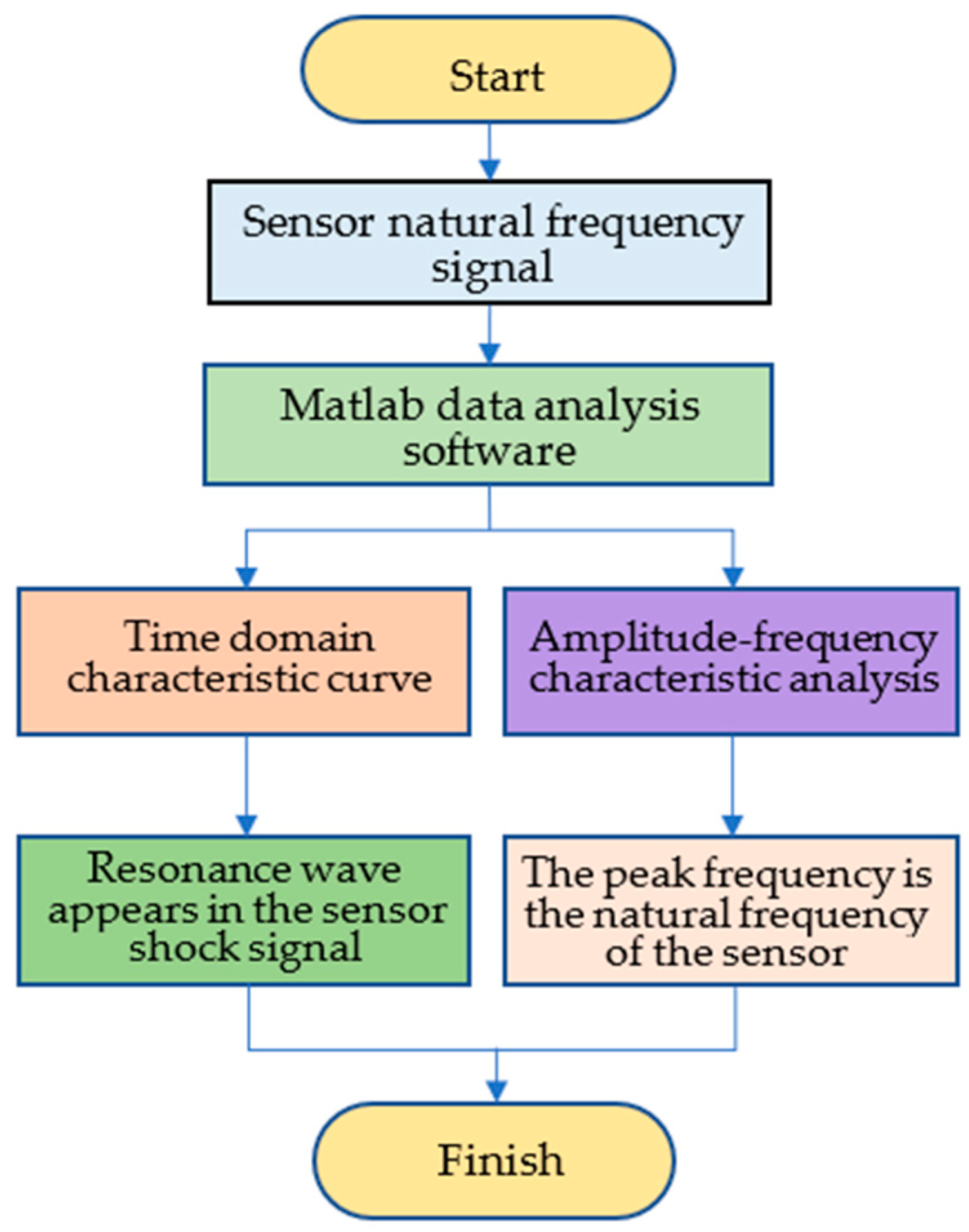
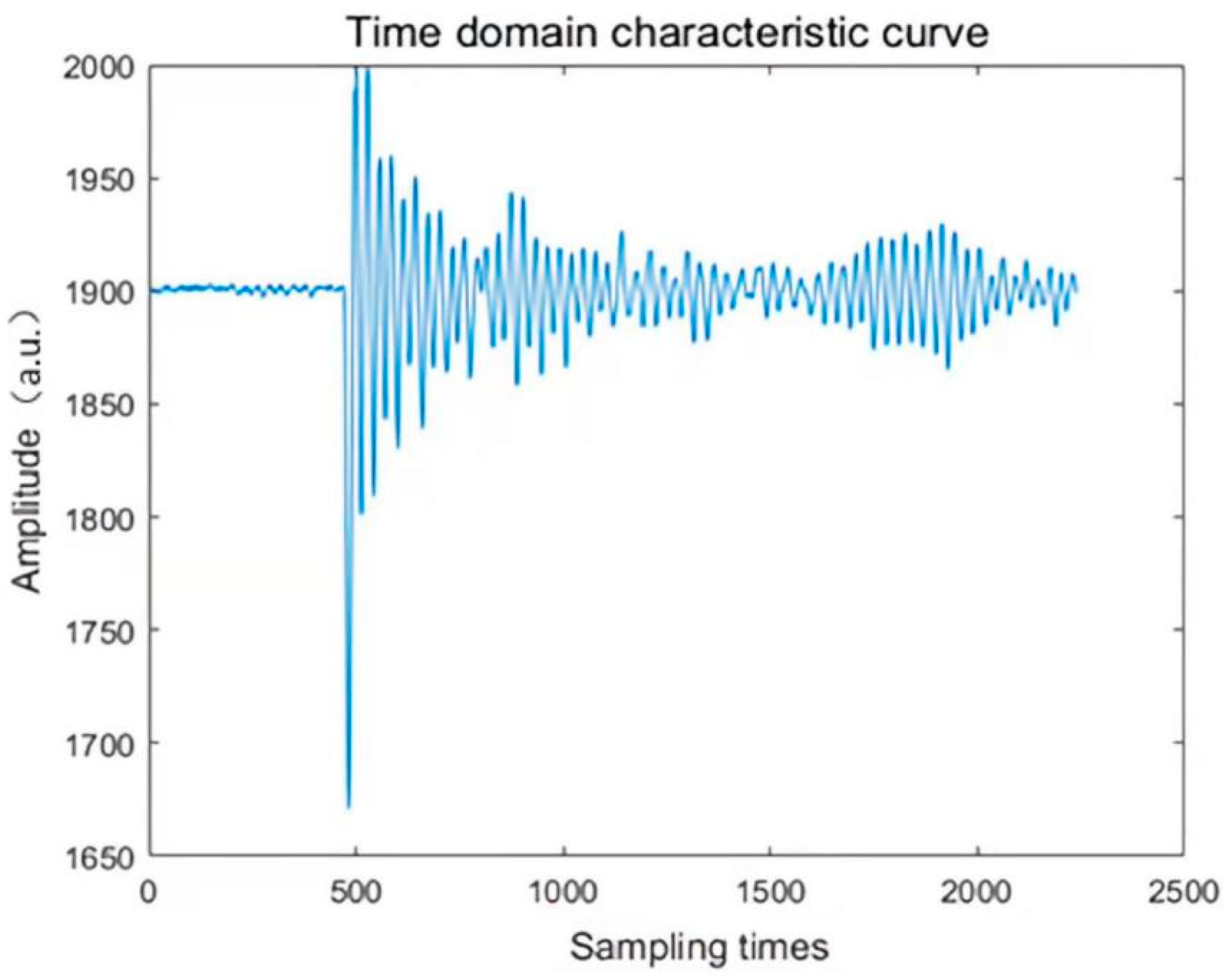
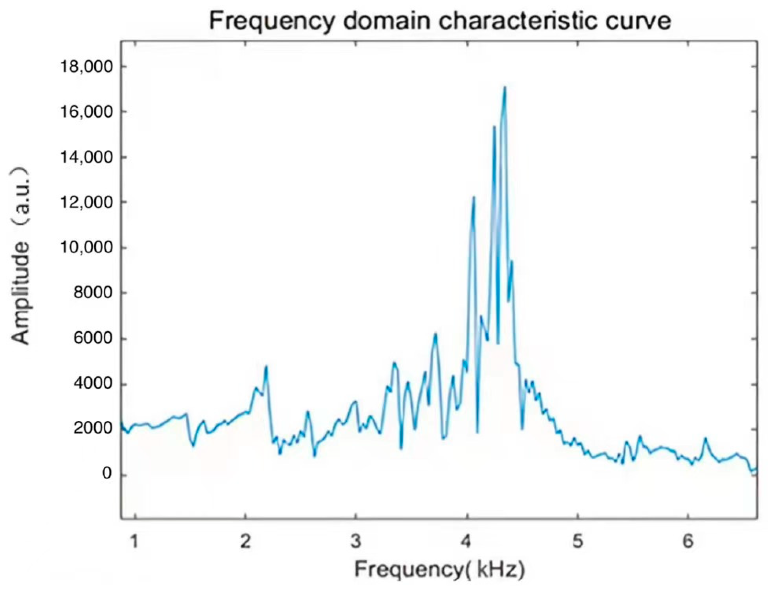
5.2. Natural Frequency Data Processing Method of the Resonance Sensor

To accurately, but quickly, perform a spectral analysis on the waveform data, Matlab was selected as the software to process the data. Matlab facilitates the import of data, and it integrates the FFT operation function with parameters that can easily be set. By calling the FFT function inside Matlab to perform the fast Fourier transform on the data, it not only greatly reduces the amounts of calculations required and improves the calculational efficiency, but also reduces the cumulative quantization error. To facilitate the observation, and the analysis of the time–domain and frequency–domain characteristics of the waveform, Figure 8 displays the data analysis flow chart for the impact response of the resonant sensor with respect to the impact of the falling ball.
The natural frequency of the resonant sensor was measured via the impact method, and the amplitude data of the strain waveform of the FBG strain sensor was also obtained. Figure 9 depicts the amplitude data for a set of resonant FBG knock sensors. Due to the large amount of data, represented by the intercepted data volume being set at 2240, the waveform data corresponds to the intercepted maximum strain peak. It can be seen that the waveform is doped with many high-frequency signals. The abscissa represents time, and the ordinate depicts the amplitude of the FBG strain sensor. Through both observation and analysis of the data, it was found that the output strain waveform has many aliasing high-frequency signals, which makes it more difficult to extract the strain waveform curve and the strain peak value. Setting the sampling frequency to 300 kHz in Matlab and the length of the collected signal to the number of data points, Figure 10 shows the frequency spectrum that is obtained after FFT of the strain waveform data in Figure 9.

6. Discussion

From this amplitude–frequency characteristic diagram Figure 10, it can be seen that there is a main resonance peak at around 4.3 kHz. The experimental data are highly consistent with the theoretical simulation data, as the nature frequency of fourth-order mode is 4.3619 kHz in Figure 5. According to the resonance mechanism, the FBG knock sensor will be stimulated achieving a resonance state, when engine deflagration happens continuously. If the ECU monitor the FBG knock sensor signal is working at the nature frequency, the engine knock is occurring. That means that FBG resonant sensor encapsulated by the symmetrical rhomboid structure can be applied to the monitoring of engine knocking. The nature frequency of FBG knock sensor can be altered by changing the mass or size of the rhomboid structure for different engines.

7. Conclusions

To summarize, this paper proposes a set of resonant knock sensors that are based on FBGs, which enable anti-electromagnetic interference FBG to be the sensitive element; it converts vertical vibrations in a stretched rhomboid structure of the FBG into the horizontal direction. The elastic body, as the basic structure of the sensor, and the mass constitute a mechanical second-order system. The resonant frequency of the mechanical second-order system is caused by the impact of knocking. After a comprehensive analysis of the characteristic curve of the FBGs knock sensor, which is subjected to a high voltage impact from spark plug, the vibrational signal obtained from the FBG demodulator represents a pure spectral characteristic curve, without the influence of electromagnetic interference. Moreover, the peak data of the knock waveform and the experimental results match the simulation data, which can reach 4361.9 Hz. This proves the feasibility of the engine knock sensor. In the future, we will further optimize the encapsulated structure on the existing basis to make it more miniaturized and lightweight. The FBG knock sensor has a simpler and more stable structure that can be used in harsher environments. Based on sparkless and safe features, optical fiber sensing provides a new means of explosion-proof and anti-electromagnetic interference for knock monitoring of gasoline and diesel engines as well as new energy engines, such as hydrogen and natural gas, and also provides better help for future driverless cars.

Author Contributions

Investigation, visualization, Data Curation, Writing—Original Draft, H.S.; Conceptualization, Methodology, Supervision, Writing—Review and Editing, D.Y. All authors have read and agreed to the published version of the manuscript.

Funding

This research was funded by National Key Research and Development Program, grant number 2017YFD0700802-2.

Institutional Review Board Statement

Not applicable.

Informed Consent Statement

Not applicable.

Data Availability Statement

Data generated or analyzed during the study are available from the corresponding author by request.

Conflicts of Interest

The authors declare no conflict of interest.

References

  1. Knuutila, L. Blending Strategies and Process Modification for the Future Gasoline Production. Master’s Thesis, Programme in Advance Energy Solutions, Aalto University, Espoo, Finland, 2019. [Google Scholar]
  2. Kalghatgi, G. Developments in internal combustion engines and implications for combustion science and future transport fuels. Proc. Combust. Inst. 2015, 35, 101–115. [Google Scholar] [CrossRef]
  3. Chen, L.; Li, T.; Yin, T.; Zheng, B. A predictive model for knock onset in spark-ignition engines with cooled EGR. Energy Convers. Manag. 2014, 87, 946–955. [Google Scholar] [CrossRef]
  4. Pan, J.; Wei, H.; Shu, G.; Chen, R. Effect of pressure wave disturbance on auto-ignition mode transition and knocking intensity under enclosed conditions. Combust. Flame 2017, 185, 63–74. [Google Scholar] [CrossRef] [Green Version]
  5. Li, T.; Wu, D.; Xu, M. Thermodynamic analysis of EGR effects on the first and second law efficiencies of a boosted spark-ignited direct-injection gasoline engine. Energy Convers. Manag. 2013, 70, 130–138. [Google Scholar] [CrossRef]
  6. Wei, H.; Shang, Y.; Chen, C.; Gao, D.; Feng, D. A numerical study on pressure wave-induced end gas auto-ignition near top dead center of a downsized spark ignition engine. Int. J. Hydrogen Energy 2014, 39, 21265–21274. [Google Scholar] [CrossRef]
  7. Alkidas, A.C. Combustion advancements in gasoline engines. Energy Convers. Manag. 2007, 48, 2751–2761. [Google Scholar] [CrossRef]
  8. Wang, Z.; Liu, H.; Reitz, R.D. Knocking combustion in spark-ignition engines. Prog. Energy Combust. Sci. 2017, 61, 78–112. [Google Scholar] [CrossRef]
  9. Dai, P.; Chen, Z.; Gan, X.; Liberman, M.A. Autoignition and detonation development from a hot spot inside a closed chamber: Effects of end wall reflection. Proc. Combust. Inst. 2020, 38, 5905–5913. [Google Scholar] [CrossRef]
  10. Fitton, J.; Nates, R. Knock erosion in spark-ignition engines. SAE Trans. 1996, 105, 2318–2326. [Google Scholar] [CrossRef]
  11. Pipitone, E.; D’Acquisto, L. Development of a low-cost piezo film-based knock sensor. Proc. Inst. Mech. Eng. Part D J. Automob. Eng. 2003, 217, 691–699. [Google Scholar] [CrossRef]
  12. Li, A.; Zheng, Z. Effect of spark ignition timing and water injection temperature on the knock combustion of a GDI engine. Energies 2020, 13, 4931. [Google Scholar] [CrossRef]
  13. Wang, C.; Zhang, F.; Wang, E.; Yu, C.; Gao, H.; Liu, B.; Zhao, Z.; Zhao, C. Experimental study on knock suppression of spark-ignition engine fuelled with kerosene via water injection. Appl. Energy 2019, 242, 248–259. [Google Scholar] [CrossRef]
  14. Zhen, X.; Wang, Y.; Xu, S.; Zhu, Y.; Tao, C.; Xu, T.; Song, M. The engine knock analysis—An overview. Appl. Energy 2012, 92, 628–636. [Google Scholar] [CrossRef]
  15. Liu, H.; Wang, Z.; Qi, Y.; He, X.; Wang, Y.; Wang, J. Experiment and simulation research on super-knock suppression for highly turbocharged gasoline engines using the fuel of methane. Energy 2019, 182, 511–519. [Google Scholar] [CrossRef]
  16. Rodríguez-Fernández, J.; Ramos, A.; Barba, J.; Cardenas, D.; Delgado, J. Improving fuel economy and engine performance through gasoline fuel octane rating. Energies 2020, 13, 3499. [Google Scholar] [CrossRef]
  17. Jiang, C.; Li, Q.; Huang, J.; Bi, S.; Ji, R.; Guo, Q. Single-layer MoS2 mechanical resonant piezo-sensors with high mass sensitivity. ACS Appl. Mater. Interfaces 2020, 12, 41991–41998. [Google Scholar] [CrossRef]
  18. Li, N.; Yang, J.; Zhou, R.; Wang, Q. Knock detection in spark ignition engines using a nonlinear wavelet transform of the engine cylinder head vibration signal. Meas. Sci. Technol. 2014, 25, 115002. [Google Scholar] [CrossRef]
  19. Sivabalakrishnan, R.; Jegadheesan, C.; Li, Z.; Sha, Z. Study of knocking effect in compression ignition engine with hydrogen as a secondary fuel. Chin. J. Eng. 2014, 2014, 1–8. [Google Scholar] [CrossRef] [Green Version]
  20. Benjamín, P.; Pau, B.; Irina, J.; Carlos, G. Increasing knock detection sensitivity by combining knock sensor signal with a control oriented combustion model. Mech. Syst. Signal Process. 2022, 168, 108665. [Google Scholar] [CrossRef]
  21. Yang, Z.; Rong, H.; Wong, P.; Angelov, P.; Vong, C.; Chiu, C.; Yang, Z. A Novel Multiple Feature-Based Engine Knock Detection System using Sparse Bayesian Extreme Learning Machine. Cognit. Comput. 2022, 1–24. [Google Scholar] [CrossRef]
  22. Bares, P.; Selmanaj, D.; Guardiola, C.; Onder, C. A new knock event definition for knock detection and control optimization. Appl. Therm. Eng. 2018, 131, 80–88. [Google Scholar] [CrossRef]
  23. Pla, B.; De La Morena, J.; Bares, P.; Jiménez, I. Knock Analysis in the Crank Angle Domain for Low-Knocking Cycles Detection; Technical Paper; SAE International: Warrendale, PA, USA, 2020. [Google Scholar] [CrossRef]
  24. Novella, R.; Pla, B.; Bares, P.; Jiménez, I. Acoustic characterization of combustion chaambers in reciprocating engines: An application for low knocking cycles recognition. Int. J. Engine Res. 2020, 23, 120–131. [Google Scholar] [CrossRef]
  25. Tang, Q.; Duan, X.; Liu, Y.; Li, S.; Zhao, Z.; Ren, K.; Li, Y.; Chang, H. Experimental study the effects of acetone–butanol–ethanol (ABE), spark timing and lambda on the performance and emissions characteristics of a high-speed si engine. Fuel 2020, 279, 118499. [Google Scholar] [CrossRef]
  26. Daniel, R.; Tian, G.; Xu, H.; Shuai, S. Ignition timing sensitivities of oxygenated biofuels compared to gasoline in a direct-injection SI engine. Fuel 2012, 99, 72–82. [Google Scholar] [CrossRef]
  27. Napolitano, P.; Alfe, M.; Guido, C.; Gargiulo, V.; Fraioli, V.; Beatrice, C. Particle emissions from a HD SI gas engine fueled with LPG and CNG. Fuel 2020, 269, 117439. [Google Scholar] [CrossRef]
  28. Wei, H.; Zhang, R.; Chen, L.; Pan, J.; Wang, X. Effects of high ignition energy on lean combustion characteristics of natural gas using an optical engine with a high compression ratio. Energy 2021, 223, 120053. [Google Scholar] [CrossRef]
  29. Sahoo, S.; Srivastava, D. Effect of compression ratio on engine knock, performance, combustion and emission characteristics of a bi-fuel CNG engine. Energy 2021, 233, 121144. [Google Scholar] [CrossRef]
  30. Mohapatra, A.; Talukdar, J.; Mishra, T.; Anand, S.; Jaiswal, A.; Khanna, A.; Gupta, D. Fiber Bragg grating sensors driven structural health monitoring by using multimedia-enabled iot and big data technology. Multimed. Tools Appl. 2022, 1–21. [Google Scholar] [CrossRef]
  31. Flores-Bravo, J.A.; Madrigal, J.; Zubia, J.; Sales, S.; Villatoro, J. Coupled-core fiber Bragg gratings for low-cost sensing. Sci. Rep. 2022, 12, 1280. [Google Scholar] [CrossRef]
  32. Nan, Y.-G.; Yazd, N.S.; Chapalo, I.; Chah, K.; Hu, X.; Megret, P. Properties of Fiber Bragg Grating in CYTOP Fiber Response to Temperature, Humidity, and Strain Using Factorial Design. Sensors 2022, 22, 1934. [Google Scholar] [CrossRef]
  33. Pan, W.; Tang, W.; Zhou, W. Fiber Bragg grating strain sensor for smart structures. SPIE 1996, 2895, 166–170. [Google Scholar] [CrossRef]
  34. Rao, Y.J. Recent progress in long-period fiber grating sensors written by high-frequency CO2 laser pulses. Adv. Sens. Syst. Appl. II 2005, 5634, 1–9. [Google Scholar] [CrossRef]
  35. Pla, B.; Bares, P.; Jimenez, I.; Guardiola, C.; Zhang, Y.; Shen, T. A fuzzy logic map-based knock control for spark ignition engines. Appl. Energy 2020, 280, 116036. [Google Scholar] [CrossRef]
Figure 1. Engine knock detection and analysis process.
Symmetry 14 00711 g001
Figure 2. Design drawing of the FBG knock sensor.
Symmetry 14 00711 g002
Figure 3. Schematic of the knock sensor with the FBG array.
Symmetry 14 00711 g003
Figure 4. Depictions of the vibrational modes of the elastic elements. (a) First-order mode, (b) second-order mode, (c) third-order mode, (d) fourth-order mode, (e) fifth-order mode, and (f) sixth-order mode.
Symmetry 14 00711 g004
Figure 5. Graph showing the natural frequency of the elastic element.
Symmetry 14 00711 g005
Figure 6. Image of the actual machine object that is designed based on the simulation data.
Symmetry 14 00711 g006
Figure 7. Diagram of the device for the steel ball impact test.
Symmetry 14 00711 g007
Figure 8. Analysis flow chart relating to the natural frequency.
Symmetry 14 00711 g008
Figure 9. Graph showing the time–domain characteristic curve.
Symmetry 14 00711 g009
Figure 10. Graph showing the frequency–domain characteristic curve.
Symmetry 14 00711 g010
Publisher’s Note: MDPI stays neutral with regard to jurisdictional claims in published maps and institutional affiliations.

