Article

Analysis of the Dynamics and Strength of the Symmetrically Loaded Bearing Structure of a Tank Car with Friction Bonds Implemented by Means of Elastic Elements in the Tank Supports

1
Department of Cars and Carriage Facilities, State University of Infrastructure and Technologies, Kyrylivska Str. 9, 04071 Kyiv, Ukraine
2
Department of Transport and Handling Machines, Faculty of Mechanical Engineering, University of Zilina, Univerzitna 1, 010 26 Zilina, Slovakia
3
Department of Wagon Engineering and Product Quality, Ukrainian State University of Railway Transport, Feuerbach Square 7, 61050 Kharkiv, Ukraine
*
Author to whom correspondence should be addressed.
Symmetry 2022, 14(4), 727; https://doi.org/10.3390/sym14040727
Submission received: 16 February 2022 / Revised: 22 March 2022 / Accepted: 31 March 2022 / Published: 2 April 2022
(This article belongs to the Section Chemistry: Symmetry/Asymmetry)

Abstract

:
The article reflects the results from determining the vertical loading of the supporting structure of the tank car. A feature of the tank car is the presence of friction bonds implemented by means of elastic elements in the boiler supports on the frame, which helps to reduce the loading of the supporting structure and increase the fatigue strength. To substantiate the proposed solution, the determination of the vertical loading of the supporting structure of the tank car was carried out when driving in an empty state by rail unevenness. It was established that the use of friction bonds implemented by means of bearings makes it possible to reduce the dynamic loading of the tank car by almost 35% compared to the prototype. To determine the distribution fields of acceleration acting on the supporting structure of the tank car, as well as their numerical values, a computer simulation of the dynamic loading of its supporting structure was carried out. The calculation was carried out using the finite element method according to the Mises criterion. When carrying out calculations, elastic connections were placed between the boiler and its supports using the options of the software package. To consider the friction component, the friction force was taken into account which was applied in the zones of the interaction of the boiler with the supports. The conducted studies showed that the discrepancy between the results of analytical and numerical modeling is 7.9%. It was established that the design service life of the improved supporting structure of the tank car is more than 20% higher than the service life of the prototype car. The safety factor of fatigue strength was 4.1. The research conducted can be used by those concerned about reducing failures in the bearing structures of tank cars in operational loading modes, decreasing maintenance costs, and developing recommendations for designing innovative car structures.

1. Introduction

The compatibility of railway transport in the transportation market greatly depends on putting innovative rolling stock structures into operation [1,2]. It should be noted that the design of the bearing structures of rolling stock is of primary importance [1,3,4].
Traditionally, tank cars are used for the transportation of liquid freight (light and dark oil products). Additionally, due to the specific nature of liquid freight, special requirements should be fulfilled as early as the design stage.
The bearing structure of a tank car consists of the tank itself and the frame. The tank is supported by the frame through wooden blocks mounted in the support grooves on the frame.
The action of cyclic alternating loads on the supporting structure of a tank car during operation causes failures due to fatigue loading of the structure and requires additional costs for repair or exclusion of the tank car from the rolling stock inventory. It is important to mention that the violation of the strength of the tank car during transport is fraught with the loss of its stability and overturning. This poses a threat to the environmental and economic safety of rail transport. Thus, the issue of reducing the dynamic loading of the supporting structure of the tank car and increasing its service life is topical.
To reduce the fatigue strength of car elements under the action of cyclic loads, it is possible to use friction bonds implemented by elastic elements. It is important to mention that such connections have found application in the designs of freight cars. For example, in bogies [5,6] or harnesses [7,8] of cars. However, it is expedient to consider the possibility of their use in the supporting structures of cars.
Study [9] deals with the problems of technical diagnostics of tank cars transporting dangerous freight. The residual service life of the bearing components and the tank was determined using several evaluation criteria. The procedures for testing and diagnostics of the technical state of a tank car were improved. However, the authors did not suggest any measures to reduce the loads on the bearing structure of a tank car in operation.
Study [10] presents improvements for the structure of support elements in a tank car transporting liquid freight. The optimization design was created with numerical and graphic methods. The authors developed the finite element models of a tank car with different structural solutions of end support elements. However, they did not study the problem of reducing the dynamic loading on a tank car in operation.
The results of the determination of the loading on the bearing structure of a tank car during a shunting impact are presented in [11]. The authors studied how the displacement of the liquid freight affected the stability of a tank car. The reliability of the designed models was verified by comparing with other results of the research.
The effect of the liquid freight displaced on the dynamics of a tank car was described in [12]. The dynamic model of loading on a tank car included the wheel–rail contact. It was found that the displacement of freight had a considerable effect on the distribution of loads between the front and rear bogies. However, these studies did not provide any solutions for decreasing the loading on a tank car in operation.
The dynamics and strength of the bearing structure of a tank car were determined in [13]. The effect of the displacement of the coupler head on the loading of the bearing structure of a tank car was also studied. The authors developed the requirements for designing the bearing structures of tank cars.
The strength of the bearing structure of a tank car transporting bitumen was studied in [14] with the finite element method. The authors determined the dislocation fields of the maximum equivalent stresses in the bearing structure of a tank car in main operational loading modes.
However, the authors did not suggest any solutions to decrease the dynamic loading on the bearing structure of a tank car in order to improve the service life.
Study [15] revealed the results of improvements in the bearing structure of a tank car in terms of safety operation. The results of strength calculation for the bearing structure of an improved tank car were also presented. However, the solutions regarding better strength factors of the bearing structure deal only with its reinforcement, rather than reduction in dynamic loads.
The problems associated with reducing the dynamic loading of the bearing structures of cars in operational modes are described in [16,17]. The solutions suggested were proved through analytical and numerical modeling. However, the authors did not study the issue of decreasing the dynamic loading on the bearing structure of a tank car.
In [18], possible options for improving tank cars are considered. Introducing the construction of a tank car with cone-like cantilever components is substantiated. The results on the strength of the supporting structure of the tank car are presented.
Measures aimed at increasing the productivity and efficiency of liquid cargo transportation in tank cars are covered in [19]. The most rational, from the point of view of operational efficiency, version of the design of the supporting structure of the tank car is proposed.
It is important to say that the proposed solutions do not contribute to the reduction in dynamic loading of the supporting structure of the tank car in operation.
Features of computer simulation of the loading of the supporting structure of a tank car are presented in [20]. At the same time, attention is paid to the study of the loading of the manhole hatch. Solutions for improving its design are proposed.
In [21], solutions were proposed to ensure the strength of the fastening details of the boiler to the frame of the tank car. The authors also proposed solutions to ensure the reliability of fastening the shaped paw to the main beam.
However, the solutions proposed by the authors are aimed at strengthening the supporting structure, and not at reducing its dynamic loading.
The scientific publication [22] is of interest. This paper presents a methodology for determining the service life of a tank car. The nodes of the structure, subject to the greatest loading, are determined. At the same time, solutions aimed at increasing the service life of a tank car were not proposed in the work.
The effect of cyclic loading of the tank car boiler on its strength is carried out in [23]. The main indicators of the strength of the boiler are determined. The results of the calculation for fatigue strength are also presented. Similar studies are presented in [24]. At the same time, the authors revealed the influence of external loads on the appearance of cracks in the boiler. However, no solutions have been proposed to improve the load-bearing structures of tank cars to ensure their strength in operation.
For known designs of tank cars, solutions are proposed to reduce the dynamic loading of their components. An example is a patent [25]. A feature of the tank car is that the middle part of the frame is formed by additional lodgments, between the sheet of which and the shell of the boiler an elastic gasket is installed.
Patent [26] proposes a support unit for a boiler of a railway tank car, containing a support with a curved sheet, on which receptive elastic support elements are fixed with the help of fixing elements, made in the form of separate support plates. The material for their manufacture is high-molecular-weight polyethylene.
Patent [27] describes a device for fixing a railway tank boiler on a frame, including a collar around the boiler, consisting of a belt and threaded tips, which are connected to the frame cradles by means of elastic elements and nuts.
The patent [28] proposes a support unit for a tank car boiler located on a pivot beam, which includes side supports containing diaphragms connected to each other by reinforcing ribs and a radially curved sheet on which elastic compensators are laid.
The source [29] describes the design of a tank car, in which the boiler rests on a lodgment covering the lower part of the boiler at an angle of 120° through elastic polyurethane gaskets. Moreover, the gaskets are made to be similar in height, which makes it possible to compensate for the gaps between the boiler and the support that arise due to technological manufacturing tolerances.
The patent [30] proposes the design of a tank car with a filler in the center sill. The proposed solution makes it possible to reduce the dynamic loading of the car in the longitudinal plane under operating modes such as “impact”, “tension–compression”, and “jerk”.
It is important to note that the considered designs of tank cars include elastic components that compensate for dynamic loading under operating conditions. However, it is more expedient to use friction bonds implemented in the most loaded nodes of the supporting structure of the tank car. Therefore, it is necessary to conduct research in this direction.
The objective of the article is to reveal analysis results on the dynamics and strength of the symmetrically loaded bearing structure of a tank car with friction bonds implemented by means of elastic elements in the tank supports. The following tasks were set to achieve the objective:
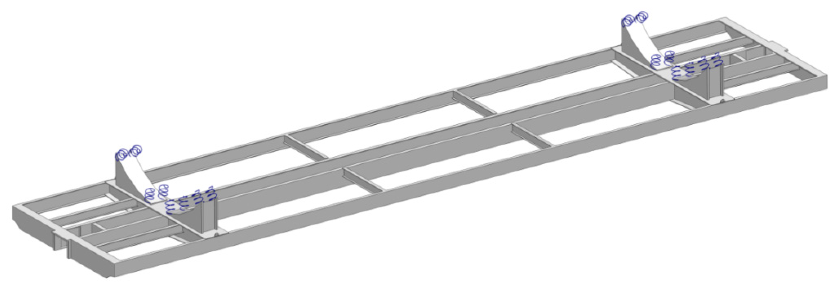
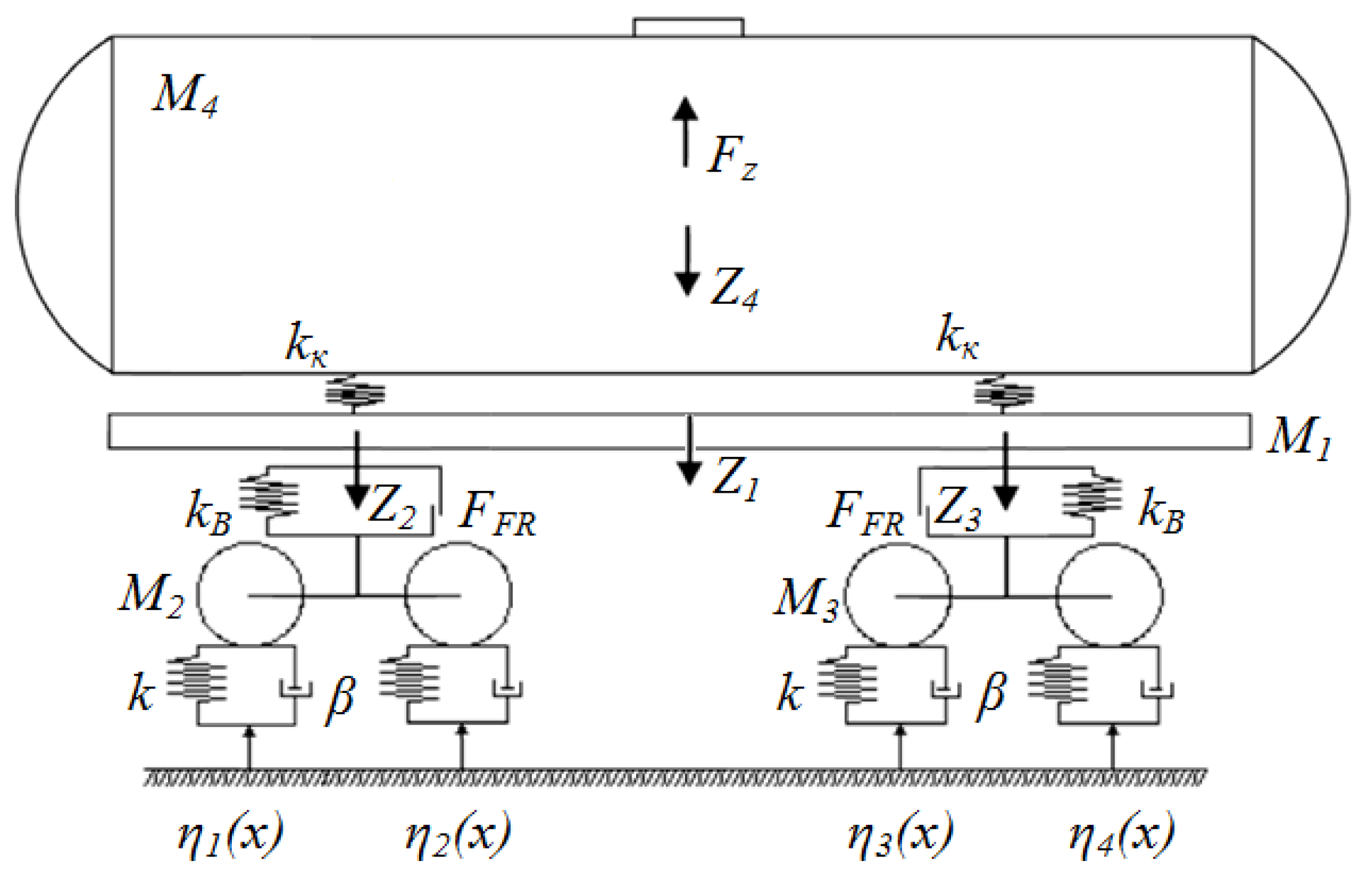
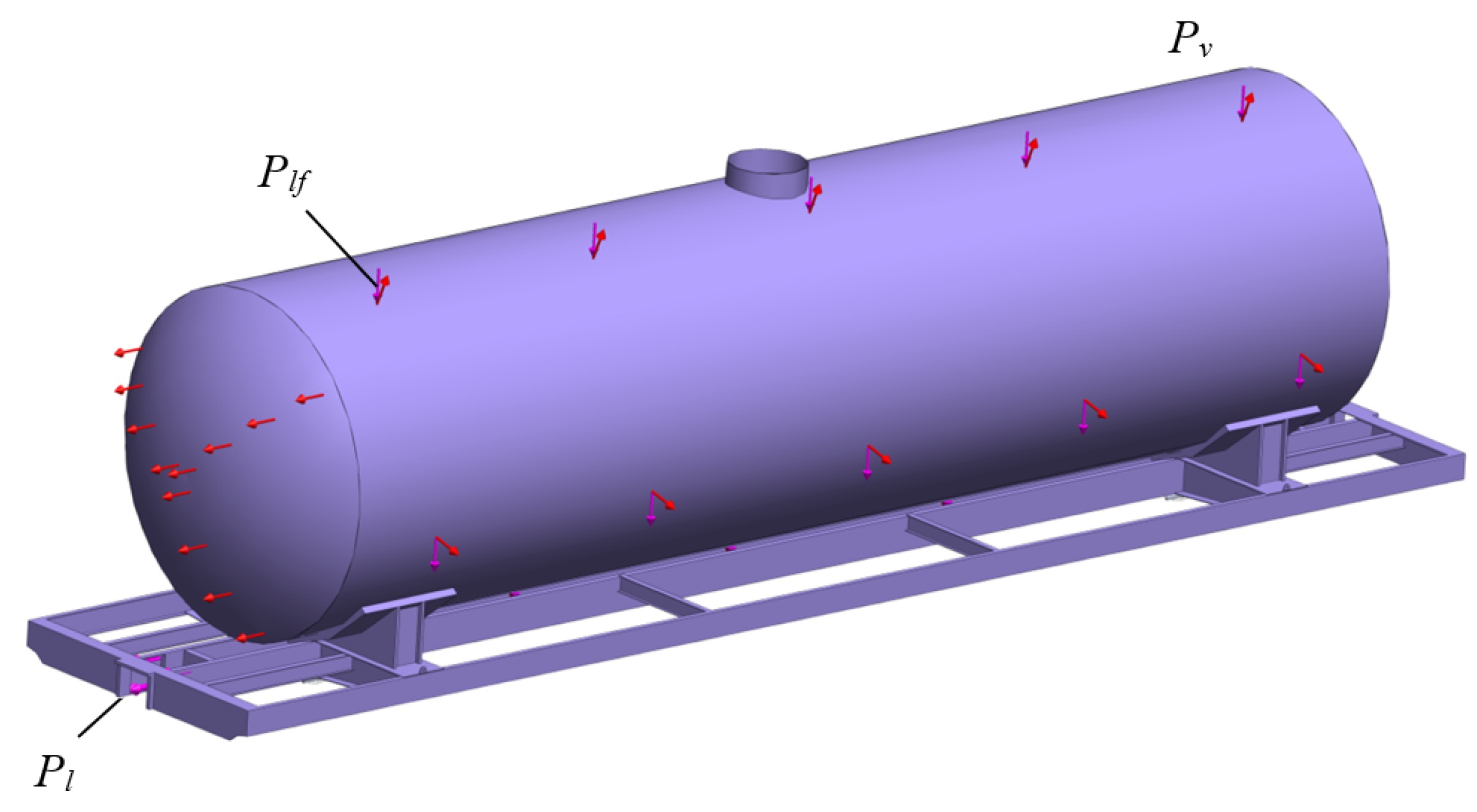
  • determining the vertical loading of the bearing structure of a tank car with friction bonds implemented by means of elastic elements in the tank supports;
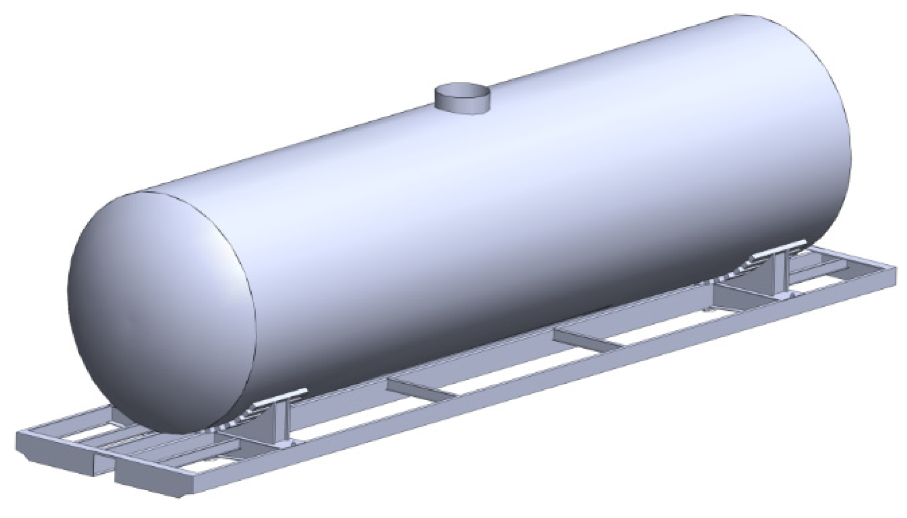
  • calculating the strength of the bearing structure of a tank car;
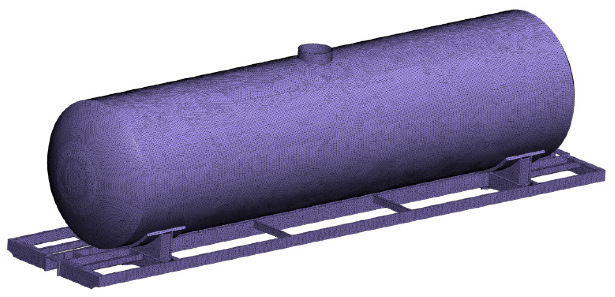
  • to carry out the computer simulation of dynamic loading of the supporting structure of a tank car with friction bonds implemented by means of elastic elements in the tank car supports;
  • determining the design service life and the safety factor of fatigue strength of the bearing structure of a tank car.

2. Materials and Methods

The dynamic loading on a tank car can be decreased through the application of friction bonds implemented by means of elastic elements between the tank and its support (Figure 1). The solution was proposed at the concept level; therefore, at this stage of the study, the features of the placement of elastic elements on the boiler supports and options for their implementation were not considered (material with appropriate properties or devices operating on the principle of a friction damper). This implementation is mainly aimed at reducing the dynamic loading of the supporting structure of the tank car in the vertical plane since bouncing oscillations are the most common type of car movement in operation. In this connection, within the framework of this article, it was the vertical movements of the tank car that were investigated.
The vertical acceleration of the tank was determined by means of analytical modeling. The design diagram of a tank car is provided in Figure 2. It is assumed that the tank car consists of three bodies: a boiler, a frame, and running gear.
The motion equations for a tank car included the motion of an empty tank car along the elastic–viscous track [31]. It was assumed that the tank car moves in an elastic–viscous track. It was assumed that the track behavior was proportional to both its deformation and the speed of this deformation. It was considered that the displacements of the frame and bogies of the tank car along the track axis were the same. The model does not take into account the slippage of wheelsets during their movement.
The differential equations of this motion of a tank car are as follows:
M 1 · q ¨ 1 + C 1 , 1 · q 1 + C 1 , 2 · q 2 + C 1 , 3 · q 3 = F F R · ( s i g n ( δ ˙ 1 ) + s i g n ( δ ˙ 2 ) ) F z ,
M 2 · q ¨ 2 + C 2 , 1 · q 1 + C 2 , 2 · q 2 + B 2 , 2 · q ˙ 2 = F F R · s i g n ( δ ˙ 1 ) + k ( η 1 + η 2 ) + β ( η ˙ 1 + η ˙ 2 ) ,
M 3 · q ¨ 3 + C 3 , 1 · q 1 + C 3 , 3 · q 3 + B 3 , 3 · q ˙ 3 = F F R · s i g n ( δ ˙ 2 ) + k ( η 3 + η 4 ) + β ( η ˙ 3 + η ˙ 4 ) ,
M 4 · q ¨ 4 = F z M 4 · g ,
F z = k k ( y 1 y 4 ) ,  
where M1—mass of the bearing structure of a tank car; M2, M3—mass of the first and second bogies facing the engine, respectively; M4—tank mass; Cij—elasticity characteristics of the elements of the oscillation system, determined through the rigidity coefficients of the springs kB; Bij—dissipation function; FFR—absolute friction force in a spring group; δi—deformation of elastic elements of spring suspension; η(t)—track irregularity; F z —the vertical load acting on the boiler during bouncing oscillations; k k —the rigidity of elastic elements on which the boiler rests.
Equations (1)–(4) included:
Z1~q1—coordinate that describes advance displacements of the frame relative to the vertical axle;
Z2~q2—coordinate that describes advance displacements of the first bogie facing the engine relative to the vertical axle;
Z3~q3—coordinate that describes advance displacements of the second bogie facing the engine relative to the vertical axle; and
Z4~q4—coordinate that describes advanced displacements of the tank relative to the vertical axle.
The contact between the bearing structure and the running part was described as a sequential elastic connection:
k k = k k · ( k B + k B ) k k + ( k B + k B ) .
An irregularity of the track was described by the periodic function [31]:
η ( t ) = d 2 ( 1 cos ω t ) ,
where d—set irregularity depth; ω—oscillation frequency.
The input parameters for the analytical model are given in Table 1 [31]. The calculation was based on the parameters of an 18–100 bogie.
At the same time, the rigidity of the elastic elements in the boiler supports was equal to 4000 kN/m and determined by calculation from the condition of ensuring the dynamics of the tank car within the allowable values. That is, the vertical acceleration should not exceed 0.75 g when the car is moving in an empty state and 0.65 g when loaded for the “permissible” motion of the car [32,33].
The limitation of the analytical model (1)–(4) is that it does not take into account fluctuations of bulk cargo in the boiler, i.e., the load is considered as an attached mass, which completely repeats the movement of the boiler in the vertical plane.
The calculation was completed for a 15-1443-06 tank car for transportation of light oil products (Figure 3). The manufacturer of this tank car is the Public Joint Stock Company “Poltavkhimmash” (Poltava, Ukraine).
Differential Equations (1)–(4) were solved in MathCad [34,35].
When solving differential Equations (1)–(4), the authors used the rkfixed function, which is the implemented function of the 4th order Runge–Kutta method with a constant integration step. This function was chosen because, based on the experience of previous studies on the dynamics of cars carried out by the authors of the article, it allows to obtain good convergence of analytical and numerical modeling. Before calling the function, values were assigned to the variables Y 0 , t n ,   t k , n , and F , where t n ,   t k are the values that determine the initial and final integration variables, n is a fixed number of steps, and F is a symbolic vector.
The initial value of the array is ORIGIN = 1. The solution of Equations (1)–(4) was carried out in hourly intervals from 0 to 5 s; therefore, t n = 0 and t k = 5. The number of nodes of the uniform grid is assumed to be 5000, i.e., the integration step is 0.0001 s [31].
The initial displacements and speeds were taken as equal to zero.
The models were solved in MathCad in the form:
F ( t , y ) = [ y 5 y 6 y 7 y 8 F F R · ( s i g n ( δ ˙ 1 ) + s i g n ( δ ˙ 2 ) ) C 1 , 1 · y 1 C 1 , 2 · y 2 C 1 , 3 · y 3 F z M 1 F F R · s i g n ( δ ˙ 1 ) + k ( η 1 + η 2 ) + β ( η ˙ 1 + η ˙ 2 ) C 2 , 1 · y 1 C 2 , 2 · y 2 B 2 , 2 · y 6 M 2 F F R · s i g n ( δ ˙ 2 ) + k ( η 3 + η 4 ) + β ( η ˙ 3 + η ˙ 4 ) C 3 , 1 · y 1 C 3 , 3 · y 3 B 3 , 3 · y 7 M 3 F z M 4 · g M 4 ] , Z = r k f i x e d ( Y 0 ,   t n ,   t k ,   n ,   F ) .
In this case:
y 1 = q 1 ,   y 2 = q 2 ,   y 3 = q 3 ,   y 4 = q 4 ,   y 5 = y ˙ 1 ,   y 6 = y ˙ 2 ,   y 7 = y ˙ 3 ,   y 8 = y ˙ 4 .
The generalized acceleration was calculated in the array ddqj,i:
d d q j , 1 = F F R · ( s i g n ( δ ˙ 1 ) + s i g n ( δ ˙ 2 ) ) C 1 , 1 · y 1 C 1 , 2 · y 2 C 1 , 3 · y 3 F z M 1 ,
d d q j , 2 = F F R · s i g n ( δ ˙ 1 ) + k ( η 1 + η 2 ) + β ( η ˙ 1 + η ˙ 2 ) C 2 , 1 · y 1 C 2 , 2 · y 2 B 2 , 2 · y 6 M 2 ,
d d q j , 3 = F F R · s i g n ( δ ˙ 2 ) + k ( η 3 + η 4 ) + β ( η ˙ 3 + η ˙ 4 ) C 3 , 1 · y 1 C 3 , 3 · y 3 B 3 , 3 · y 7 M 3 ,
d d q j , 4 = F z M 4 · g M 4 ,
MathCad graphics editor was used to make the results more accurate. The index of the rows of the matrix Z is denoted by j. It is assumed that j is in the range 1–5000.
The next stage of the research included the strength calculation of the bearing structure of a tank car. The geometric model of the supporting structure of the tank car was created in the SolidWorks software package (Figure 4).
The calculation was undertaken using the finite element method in SolidWorks Simulation. The calculation was carried out according to the Mises criterion (IV energy theory). The finite element model of the bearing structure of a tank car is presented in Figure 5. The optimal number of elements in the mesh was defined with the graphic analytical method [36,37]. Spatial isoparametric tetrahedrons were taken as the finite elements [38,39,40]. In this case, the dependence of stresses on the number of grid elements was constructed. Based on the calculations, it was found that this dependence is linear. Grid-independent solutions are unaffected by grid refinement, resulting in a stable solution. There is no difference in rpm when the number of elements reaches 721,195.
The number of elements in the mesh was 721,195, and nodes—232,420. The maximum element size in a mesh was 40 mm, the minimum size was 8 mm, the maximum element side ratio was 93.724; the percentage of elements with a side ratio of less than three was 21.8 and more than 10 was 0.414.
The design diagram of the bearing structure of a tank car is presented in Figure 6. The strength of the bearing structures of a tank car was calculated for Design Mode I (jerk–torsion). It was considered that the following loads impact the bearing structure: longitudinal load Pl that was applied to the front supports of couplers and equaled 2.5 MN, pressure from the liquid freight Plf, and vertical load Pv that included the dynamic load determined through analytical modeling. At the same time, it was considered that the load Pl was applied without taking into account the deflection of the automatic coupler in the longitudinal plane.
The model was secured in the areas of support on the bogies. Steel 09G2S was taken as the structural material. The material has linear elastic isotropic properties. The main strength properties of the material are summarized in the Table 2.
When carrying out calculations, elastic bonds were placed between the boiler and its supports using the options of the software package. To consider the friction component, the friction force was taken into account, which was applied in the interaction zones of the boiler with the supports.
To determine the distribution fields of acceleration acting on the supporting structure of the tank car, as well as their numerical values, numerical simulation of the dynamic loading of its supporting structure was carried out. The studies were carried out in accordance with the design scheme shown in Figure 6 in the SolidWorks Simulation software package. However, the model did not consider the longitudinal loads acting on the supporting structure of the tank car.
Additionally, within the framework of the study, the design service life of the supporting structure of the tank car was calculated.
The design service life of a tank car was determined with the method presented in [41]:
T n = ( σ 1 E / [ n ] ) m · N 0 B · f d · σ a d m ,
where σ−1E—average value of the endurance limit; n—allowable strength factor; m—fatigue curve exponent; N0—test base; B—coefficient characterizing continuous operation in seconds; fd—efficient frequency of dynamic stresses; σad—amplitude of equivalent dynamic stresses.
The amplitude of the equivalent dynamic stresses was determined using the formula:
σ a d = σ s t ( k d v + ψ σ / K σ ) ,
where σst—stresses caused by the static weight load; kdv—vertical dynamic coefficient; ψσ—sensitivity coefficient; Kσ—overall fatigue strength reduction coefficient.
The determination of the amplitude of equivalent dynamic stresses included the side force coefficient equal to 1.1.
The following input parameters were used in the calculation: σ1E = 245 MPa; n = 2; m = 8; N0 = 107; B = 3.07 × 10⁶ s; fd = 2.7 Hz; ψσ/Kσ = 0.2.
The stresses from the static weight load of the bearing structure of a tank car were determined through the strength calculation. It was found that the maximum equivalent stresses in the bearing structure of a tank car were approximately 90 MPa.
The fatigue strength of the bearing structure of a tank car was also calculated.
The calculation included the safety factor n and was undertaken according to the formula [42]:
n = σ 1 E σ a , s [ n ] ,
where σa,s—design amplitude of the dynamic stress of the conditional symmetry cycle, reduced to the base N0; it is equivalent in terms of the damaging effect to the values of amplitudes in the real mode of operational random stresses during the design service life, MPa; [n]—allowable safety factor of fatigue strength.
The reduced equivalent amplitude of dynamic stresses for the fatigue calculation σa,s in the case of the discontinuous function of stress amplitude distribution was determined in [42]:
σ a , s = N c N 0 i = 1 k P ν i f d i = 1 k σ a i m P i m ,
where Nc—total number of cycles of dynamic loading during the design service period; pσi and pvi—the probability of occurrence of the stresses with the level σi in a set speed interval and the service lifetime of a car with the speed vi; σai—stress amplitude level, MPa; kσi and kvi—numbers of discretization of stress amplitudes and speed range, respectively.
The next step in this research is the experimental determination of the dynamic loading of a tank car with friction bonds implemented by means of elastic elements in the supporting structure. This is planned to be carried out using a similarity method in the laboratory. In the future, consideration of the issues of dynamic loading of the tank car in the longitudinal plane, the choice of appropriate connections in the boiler supports, and the placement features is planned.

3. Results

Based on the calculations, the main indicators of the dynamics of the supporting structure of the tank car with frictional bonds, implemented by elastic elements in the boiler supports, were determined.
The results of the calculation are provided in Figure 7 and Figure 8.
The acceleration value of the bearing structure of a tank car in motion in a loaded state was approximately 3.0 m/s2 (0.3 g).
The maximum vertical acceleration of the bearing structure of an empty tank car was approximately 1.4 m/s2 (0.14 g), and that of the bogies was approximately 8.94 m/s2 (0.94 g). Based on this calculation, it was concluded that the motion of the car could be evaluated as excellent [37,38]. Thus, the application of friction bonds implemented by means of elastic elements supports can decrease the dynamic loading on the tank car in comparison with that of the prototype car by 35%.
The calculation was also undertaken for other main tank car models. The results of the calculation are presented in Table 3.
The analysis of the results presented in Table 2 shows that the application of friction bonds implemented by means of elastic elements between the frame and tank in a tank car is efficient and decreases their dynamic loading from 28% to 35%.
Next, the main indicators of the strength of the supporting structure of the tank car with friction bonds implemented by elastic elements were determined.
The results of the strength calculation are presented in Figure 9, Figure 10 and Figure 11.
It was found that the maximum equivalent stresses occurred in the contact area between the center sill and the body bolster; they amounted to approximately 252.8 MPa and did not exceed the allowable values [41,42]. The maximum displacements were approximately 8.3 mm.
The authors also determined the numerical values of acceleration and the fields of their distribution relative to the supporting structure of the tank car. The results of the calculations are shown in Figure 12.
The maximum acceleration values were recorded in the upper part of the boiler and amounted to 1.52 m/s2. The conducted studies showed that the discrepancy between the results of analytical and numerical modeling is 7.9%, i.e., has good convergence.
The design service life of the bearing structure of a tank car was 20% higher than that of the prototype car.
It should be noted that the service life value obtained should be adjusted by means of additional research into the longitudinal loading on the bearing structure of a tank car and through experimental (full- and bench-scale) testing.
The calculation of the safety factor for fatigue strength showed that when the probability of occurrence of stresses with a level of σi is equal to 0.95, σa,s = 59.7 MPa, its numerical value is 4.1. Due to the lack of experimental data, the allowable safety factor of fatigue strength was taken as equal to 2.2. Thus, the condition (15) was met and the fatigue strength of the bearing structure of a tank car was provided.
It should be mentioned that these solutions proved to be efficient for tank cars with composite tanks. The tare weight of a car is reduced and the strength requirements are met.

4. Conclusions

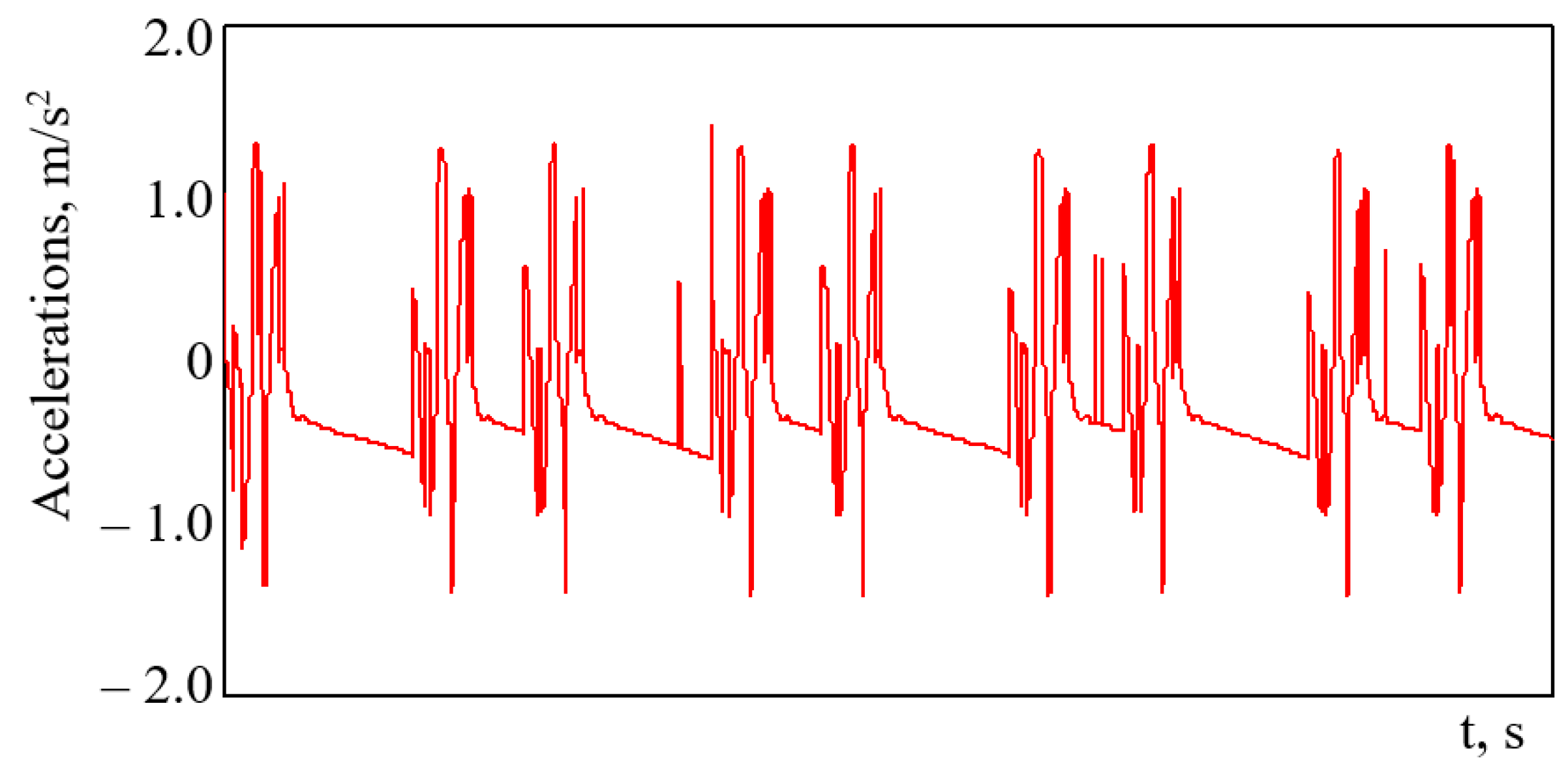
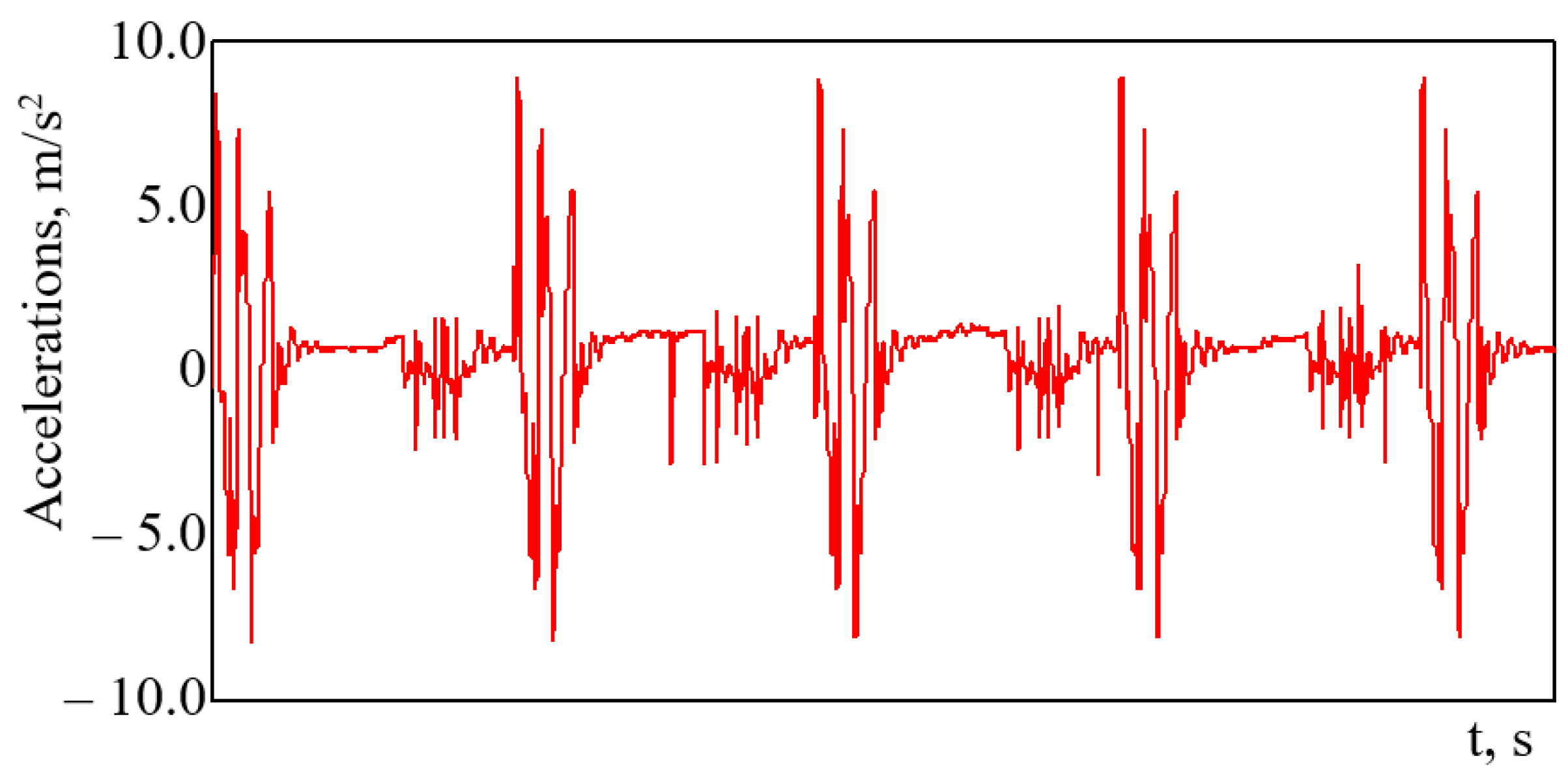
  • The vertical loading of the bearing structure of a tank car with friction bonds implemented by means of elastic elements in the tank supports was determined. The maximum vertical acceleration of the bearing structure of an empty tank car was approximately 1.4 m/s2 (0.14 g), and that of the bogies—approximately 8.94 m/s2 (0.94 g). Additionally, the motion of the car was evaluated as excellent. The application of friction bonds implemented by means of elastic elements can decrease the dynamic loading on a tank car in comparison with that of the prototype car by 35%.
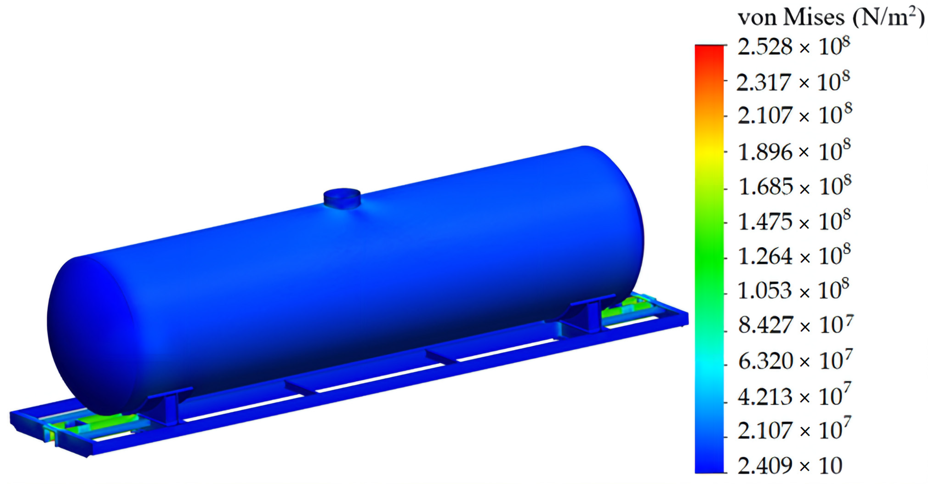
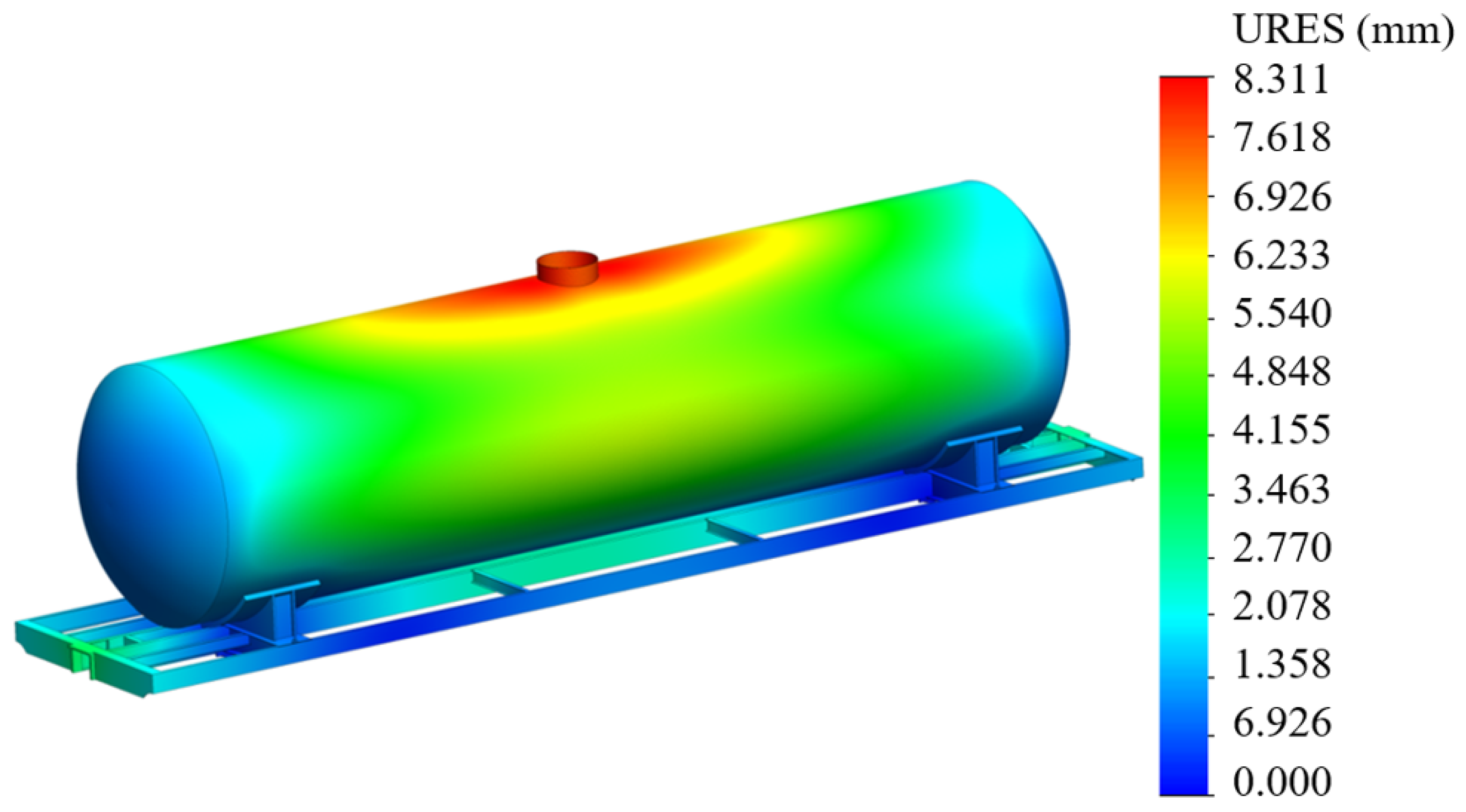
  • The strength of the bearing structure of a tank car was calculated. The maximum equivalent stresses were in the contact area between the center sill and the body bolster; they amounted to 252.8 MPa and did not exceed the allowable values for the 09G2S Steel. The maximum displacements were approximately 8.3 mm.
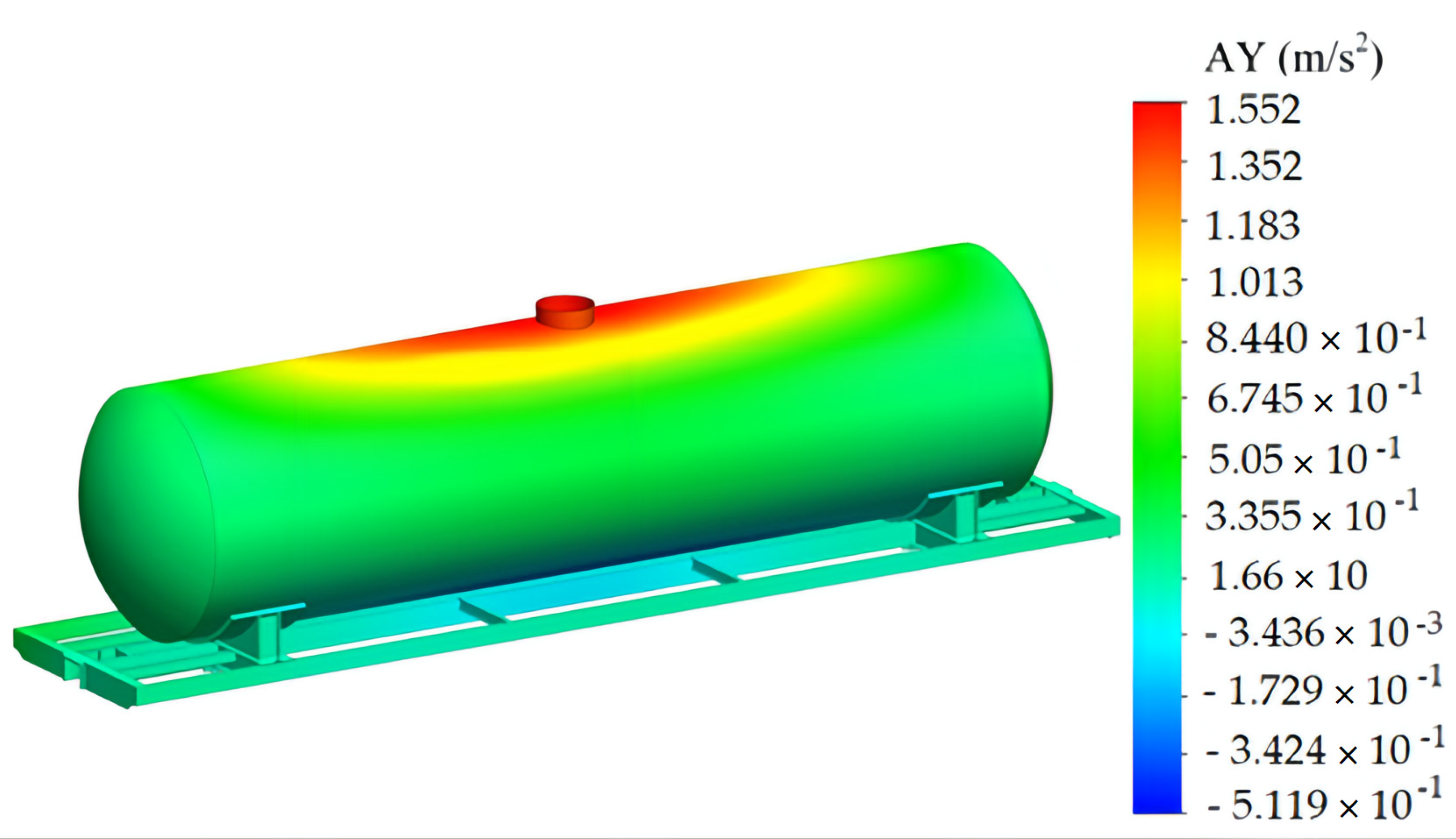
  • Computer modeling of dynamic loading of the supporting structure of a tank car with friction bonds implemented by means of elastic elements in the tank supports was carried out. The maximum acceleration values were recorded in the upper part of the boiler and amounted to 1.52 m/s2. The conducted studies showed that the discrepancy between the results of analytical and numerical modeling is 7.9%, i.e., has good convergence.
  • The service life and the safety factor of fatigue strength of the bearing structure of a tank car were determined. The design service life of the bearing structure of a tank car was 20% higher than that of the prototype car. The safety factor of fatigue strength equaled 4.1, which exceeded the allowable value by a factor of two.
The research conducted can be used by those concerned about decreasing failures in the bearing structures of tank cars in operation, their maintenance costs, and developing recommendations for designing innovative cars.

5. Patents

Fomin O. V., Lovska A. O. Tank car with elastic elements in the bearing design: pat. 148122 Ukraine: IPC (January 2021) B61D 5/00; application 20 January 2021; publ. 8 July 2021. Bull. №27. (in Ukr.).

Author Contributions

Conceptualization, O.F. and A.L.; methodology, O.F. and A.L.; software, A.L.; validation, A.L. and J.G.; investigation, O.F., A.L. and K.K.; resources, O.F., A.L. and K.K.; writing—original draft preparation, O.F., A.L. and K.K.; writing—review and editing J.G.; visualization, O.F., A.L. and K.K.; supervision, J.G. All authors have read and agreed to the published version of the manuscript.

Funding

This publication was issued thanks to support from the Cultural and Educational Grant Agency of the Ministry of Education of the Slovak Republic in the projects, Implementation of modern methods of computer and experimental analysis of properties of vehicle components in the education of future vehicle designers (Project No. KEGA 036ŽU-4/2021), Development of advanced virtual models for studying and investigation of transport means operation characteristics (No. KEGA 023ŽU-4/2020). This research was also supported by the Slovak Research and Development Agency of the Ministry of Education, Science, Research and Sport of the Slovak Republic in Educational Grant Agency of the Ministry of Education of the Slovak Republic in the project and VEGA 1/0513/22 “Investigation of the properties of railway brake components in simulated operating conditions on a flywheel brake stand”.

Institutional Review Board Statement

Not applicable.

Informed Consent Statement

Not applicable.

Data Availability Statement

Not applicable.

Conflicts of Interest

The authors declare no conflict of interest.

References

  1. Štastniak, P.; Kurčík, P.; Pavlík, A. Design of a new railway wagon for intermodal transport with the adaptable loading platform. MATEC Web Conf. 2018, 235, 00030. [Google Scholar] [CrossRef]
  2. Dižo, J.; Harušinec, J.; Blatnický, M. Computation of modal properties of two types of freight wagon bogie frames using the finite element method. Manuf. Technol. 2018, 18, 208–214. [Google Scholar] [CrossRef] [Green Version]
  3. Štastniak, P.; Moravčík, M.; Smetanka, L.; Baran, P. Strength investigation of Main Frame in New Track friendly Railway Bogie. Manuf. Technol. 2018, 18, 315–320. [Google Scholar] [CrossRef] [Green Version]
  4. Dižo, J.; Harušinec, J.; Blatnický, M. Structural analysis of a modified freight wagon bogie frame. MATEC Web Conf. 2017, 134, 00010. [Google Scholar] [CrossRef]
  5. Iwnicki, S.D.; Stichel, S.; Orlova, A.; Hecht, M. Dynamics of railway freight vehicles. Veh. Syst. Dyn. 2015, 53, 995–1033. [Google Scholar] [CrossRef] [Green Version]
  6. Savoskin, A.N.; Akishin, A.A.; Yurchenko, D. Dynamics and optimization of a new double-axle flexible bogie for high-speed trains. Proc. Inst. Mech. Eng. Part F J. Rail Rapid Transit 2018, 232, 1549–1558. [Google Scholar] [CrossRef]
  7. Wu, Q.; Cole, C.; Spiryagin, M.; Ma, W. Preload on draft gear in freight trains. Proc. Inst. Mech. Eng. Part F J. Rail Rapid Transit 2018, 232, 1615–1624. [Google Scholar] [CrossRef]
  8. Nikitchenko, A.; Artiukh, V.; Shevchenko, D.; Murgul, V. Modeling of Operation of Elastic-frictional Draft Gear by NX Motion Software. Procedia Eng. 2017, 187, 790–796. [Google Scholar] [CrossRef]
  9. Shushmarchenko, V.O.; Fedorov, V.V.; Strinzha, A.M.; Fedosov-Nikonov, D.V. On the issue of technical diagnostics of tank cars for the transport of dangerous goods. Collect. Sci. Work. Railw. Roll. Stock 2020, 20, 89–95. [Google Scholar]
  10. Vatulia, G.; Falendysh, A.; Orel, Y.; Pavliuchenkov, M. Structural Improvements in a Tank Wagon with Modern Software Packages. Procedia Eng. 2017, 187, 301–307. [Google Scholar] [CrossRef]
  11. Ashtiani, I.H.; Rakheja, S.; Ahmed, W. Investigation of coupled dynamics of a railway tank car and liquid cargo subject to a switch-passing maneuver. Proc. Inst. Mech. Eng. Part F J. Rail Rapid Transit 2019, 233, 1023–1037. [Google Scholar] [CrossRef]
  12. Shi, H.; Wang, L.; Nicolsen, B.; Shabana, A.A. Integration of geometry and analysis for the study of liquid sloshing in railroad vehicle dynamics. Proc. Inst. Mech. Eng. Part K J. Multi-Body Dyn. 2017, 231, 608–629. [Google Scholar] [CrossRef]
  13. Shimanovsky, A. Recent research of dynamics and strength of tank vehicles. Mech. Mach. Mech. Mater. 2016, 3, 59–70. [Google Scholar]
  14. Lim, C.H.; Goo, B.C. Structural Strength Evaluation for Tank of Tank Car used for Carrying Asphalt. J. Korean Soc. Railw. 2007, 11, 1019–1025. [Google Scholar]
  15. Barkan, C.P.L.; Saat, M.R.R.; González, F., III; Treichel, T.T. Cooperative Research in Tank Car Safety Design. TR News 2013, 286, 12–19. [Google Scholar]
  16. Lovska, A.; Fomin, O.; Píštěk, V.; Kučera, P. Dynamic Load and Strength Determination of Carrying Structure of Wagons Transported by Ferries. J. Mar. Sci. Eng. 2020, 8, 902. [Google Scholar] [CrossRef]
  17. Fomin, O.V.; Lovska, A.O.; Plakhtii, O.A.; Nerubatskyi, V.P. The influence of implementation of circular pipes in load-bearing structures of bodies of freight cars on their physico-mechanical properties. Sci. Bull. Natl. Min. Univ. 2017, 6, 89–96. [Google Scholar]
  18. Atamanchuk, N.A.; Tsyganskaya, L. Directions of tank car design improvement for oil products transportation. Transp. Russ. Fed. 2013, 3, 14–17. [Google Scholar]
  19. Sobierzansky, A.N.; Tsyganskaya, L. Improvement of Tank Car Designs. Bull. Dnipropetr. Natl. Univ. Railw. Transp. Acad. V. Lazarian. 2010, 35, 25–28. [Google Scholar]
  20. Putyato, A.V. Computer simulation of hydrodynamic loading of tank car manhole area. Journal Bul. GSTU by. P.O. Sukhoi». 2009, 1, 79–86. [Google Scholar]
  21. Senko, V.I.; Shimanovsky, A.O.; Putyato, A.V. Research of ways to improve the strength of the parts of the boiler fasteners to the frame of the railway tank. Bull. Brest State Tech. Univ. 2004, 4, 54–57. [Google Scholar]
  22. Kelrikh, M.B.; Fomin, O.V.; Prokopenko, P.M.; Sova, S.S. Theoretical aspects of determining the remaining life of the tank-car for nonhazardous vans. Bull. Natl. Univ. Ukr. Named After Volodymyr Dahl. 2020, 5, 5–9. [Google Scholar] [CrossRef]
  23. Boyko, A.; Kononova, O. Calculation of tank car boiler strength under cyclic loading. XIII Int. Colloq. Mech. Fatigue Met. 2016, 484–490. Available online: https://core.ac.uk/download/pdf/60845322.pdf (accessed on 15 February 2022).
  24. Zaripov, R.Y.; Vasilevsky, V.P. Calculation of tank-car boiler strength under cyclic loading. Bull. Kazakh Acad. Transp. Commun. by M. Tynshpayev. M. Tynyshpayev 2017, 1, 53–59. [Google Scholar]
  25. Baranovsky, A.V.; Boyko, V.V.; Grigoriev, V.N.; Dimitrienko, I.P.; Egorov, V.I.; Ermolenko, A.F.; Kaminsky, V.A.; Morozov, A.P.; Pozdnyakov, N.A.; Pupkov, A.P. Tank wagon. Russian Patent 2123444, 23 April 1997. [Google Scholar]
  26. Savushkin, R.A.; Kyakk, K.V.; Lavrenko, D.T.; Kalugin, A.V.; Shevchenko, D.V. Support assembly of the railway tank car boiler. Russian Utility Model 169984, 1 August 2016. [Google Scholar]
  27. Shipilov, G.V.; Zuban, A.T.; Barkov, I.V. Device for fastening the boiler of a railway tank on the platform frame (options). Russian Patent 2207260, 17 February 1999. [Google Scholar]
  28. Savushkin, R.A.; Kyakk, K.V.; Fedorov, S.A.; Lobanov, M.S.; Shevchenko, D.V.; Popovich, S.I. Rail tank boiler support unit. Russian Patent 175344, 31 March 2017. [Google Scholar]
  29. 4-Axle Frameless Tankers. Available online: http://scaletrainsclub.com/board/viewtopic.php?style=7&t=2056&start=20 (accessed on 29 July 2016).
  30. Fomin, O.V.; Lovska, A.O. Tank car with spring elements in the load-bearing structure. Ukraine Patent 148122, 20 January 2021. [Google Scholar]
  31. Demin, Y.V.; Chernyak, G.Y. Fundamentals of Wagon Dynamics; Tutorial; KUETT: Kiev, Ukraine, 2003; 270p. [Google Scholar]
  32. 7598:2014; DSTU. Freight Wagons. General Requirements for Calculations and Design of New and Modernized Wagons of 1520 mm Track (Non-Self-Propelled). UkrNDNTS: Kiev, Ukraine, 2015; 162p.
  33. 33211-2014; GOST. Freight Wagons. Requirements for Strength and Dynamic Properties. FGUP “STANDARTINFORM”: Moskow, Russia, 2016; 54p.
  34. Kelrykh, M.; Fomin, O. Perspective directions of planning carrying systems of gondolas. Metall. Min. Ind. 2014, 6, 64–67. [Google Scholar]
  35. Lovska, A.; Fomin, O.; Kučera, P.; Píštěk, V. Calculation of Loads on Carrying Structures of Articulated Circular-Tube Wagons Equipped with New Draft Gear Concepts. Appl. Sci. 2020, 10, 7441. [Google Scholar] [CrossRef]
  36. Lovska, A. Simulation of loads on the carrying structure of an articulated flat car in combined transportation. Int. J. Eng. Technol. 2018, 7, 140–146. [Google Scholar] [CrossRef] [Green Version]
  37. Vatulia, G.; Komagorova, S.; Pavliuchenkov, M. Optimization of the truss beam. Verification of the calculation results. MATEC Web Conf. 2018, 230, 02037. [Google Scholar] [CrossRef]
  38. Lovska, A.; Fomin, O.; Píštěk, V.; Kučera, P. Dynamic Load Modelling within Combined Transport Trains during Transportation on a Railway Ferry. Appl. Sci. 2020, 10, 5710. [Google Scholar] [CrossRef]
  39. Píštěk, V.; Kučera, P.; Fomin, O.; Lovska, A. Effective Mistuning Identification Method of Integrated Bladed Discs of Marine Engine Turbochargers. J. Mar. Sci. Eng. 2020, 8, 379. [Google Scholar] [CrossRef]
  40. Lovska, A.O. Computer simulation of wagon body bearing structure dynamics during transportation by train ferry. East.-Eur. J. Enterp. Technol. 2015, 3, 9–14. [Google Scholar]
  41. Ustich, P.A.; Karpych, V.A.; Ovechnikov, M.N. Reliability of Non-Traction Rail Rolling Stock; IG «Variant»: Moscow, Russia, 1999; 415p. [Google Scholar]
  42. Senko, V.I.; Makeev, S.V.; Komissarov, V.V.; Skorokhodov, S.A. Features of determination of coefficient of the stock resistance of fatigue of designs of the rolling stock. Bull. BSUT Sci. Transp. 2018, 1, 5–9. [Google Scholar]
Figure 1. Allocation of friction bonds implemented by means of elastic elements on the tank supports.
Symmetry 14 00727 g001
Figure 2. Design diagram of a tank car.
Symmetry 14 00727 g002
Figure 3. Tank car 15-1443-06.
Symmetry 14 00727 g003
Figure 4. A spatial model of the bearing structure of a tank car.
Symmetry 14 00727 g004
Figure 5. Finite-element model of the bearing structure of a tank car.
Symmetry 14 00727 g005
Figure 6. Design diagram of the bearing structure of a tank car.
Symmetry 14 00727 g006
Figure 7. Acceleration of the bearing structure in the mass center.
Symmetry 14 00727 g007
Figure 8. Acceleration of bogies.
Symmetry 14 00727 g008
Figure 9. Stress state of the bearing structure of a tank car in Design Mode I (jerk).
Symmetry 14 00727 g009
Figure 10. The zone of concentration of the highest stresses in the supporting structure of the tank car.
Symmetry 14 00727 g010
Figure 11. Displacements in the units of the bearing structure of a tank car in Design Mode I (jerk).
Symmetry 14 00727 g011
Figure 12. Distribution of acceleration fields relative to the supporting structure of a tank car.
Symmetry 14 00727 g012
Table 1. The input parameters for the analytical model.
ParameterValue
BEARING STRUCTURE
Mass, tons14.9
BOGIES
Mass, tons4.3
Spring suspension rigidity, kN/m8000
Relative friction coefficient0.1
TRACK
Damping coefficient, kN∙s/m200
Rigidity, kN/m100,000
Irregularity amplitude, m0.01
Irregularity length, m25
Table 2. Basic strength properties of the material.
ParameterValue
Modulus of elasticity, MPa2.1 × 105
Poisson’s ratio0.28
Shear modulus, MPa7.9 × 103
Mass density, kg/m37800
Tensile strength, MPa490
Yield strength, MPa345
Table 3. The acceleration of a tank car’s friction bonds implemented by means of elastic elements in the tank supports.
Tank Car ModelBearing Structure
Mass, Tons
Acceleration, m/s2
Bearing StructureBogies
15-145413.81.588.69
15-148015.31.488.83
15-148712.11.838.44
15-151412.51.778.48
15-152014.01.568.7
15-152216.11.458.89
15-152512.61.758.5
Publisher’s Note: MDPI stays neutral with regard to jurisdictional claims in published maps and institutional affiliations.

