Article

A Hierarchical Universal Algorithm for Geometric Objects’ Reflection Symmetry Detection

1
Faculty of Electrical Engineering and Computer Science, University of Maribor, Koroška Cesta 46, SI-2000 Maribor, Slovenia
2
Department of Computer Science and Engineering, University of West Bohemia, Technická 8, 306 14 Plzeň, Czech Republic
*
Author to whom correspondence should be addressed.
These authors contributed equally to this work.
Symmetry 2022, 14(5), 1060; https://doi.org/10.3390/sym14051060
Submission received: 12 April 2022 / Revised: 11 May 2022 / Accepted: 19 May 2022 / Published: 21 May 2022
(This article belongs to the Section Computer)

Abstract

:
A new algorithm is presented for detecting the global reflection symmetry of geometric objects. The algorithm works for 2D and 3D objects which may be open or closed and may or may not contain holes. The algorithm accepts a point cloud obtained by sampling the object’s surface at the input. The points are inserted into a uniform grid and so-called boundary cells are identified. The centroid of the boundary cells is determined, and a testing symmetry axis/plane is set through it. In this way, the boundary cells are split into two parts and they are faced with the symmetry estimation function. If the function estimates the symmetric case, the boundary cells are further split until a given threshold is reached or a non-symmetric result is obtained. The new testing axis/plane is then derived and tested by rotation around the centroid. This paper introduces three techniques to accelerate the computation. Competitive results were obtained when the algorithm was compared against the state of the art.

1. Introduction

The phenomenon of symmetry has fascinated people since ancient civilisations. Directly or indirectly, it is increasingly the subject of investigation in the arts [1], architecture [2], biology [3], medicine [4], mathematics [5], and various engineering disciplines [6,7,8]. A formal definition of symmetry can be found in [9,10]. Informally, however, a figure or an object is considered symmetrical if it is made from multiple copies of smaller units that are somehow interchangeable [11]. There are various types of symmetries [12,13]; however, the reflection and the rotation are the most common. In addition, symmetry in an object can be exposed on a global scale [14] or as a local feature [15].
Humans are extremely skilful at resolving various geometric tasks, including symmetry detection [16,17]. On the contrary, computer applications must be adapted to them, bearing in mind that geometric objects are considered to be continuous while computers work with finite arithmetic. This is the reason why a certain degree of inaccuracy should be accepted during geometric data processing. In addition, geometric data, potentially containing symmetric features, arrive in different forms: as raster images; as an output from drawing programs or CAD systems; or as a result of various scanners producing point clouds (e.g., LiDAR) or voxelized space (e.g., CT or MRI). Unfortunately, this usually requires different approaches for solving the same geometric tasks.
A lot of approaches for detecting reflection symmetry have been suggested and they are reviewed in Section 2. Many of them are demanding and therefore difficult for practitioners to reproduce. A hierarchical and easy-to-implement approach which is nonetheless efficient is proposed in this paper. The main features of the introduced algorithm are:
  • The algorithm detects the global reflection symmetry;
  • It accepts a point cloud obtained by sampling the input geometric object’s surface;
  • It works for 2D as well for 3D geometric objects with just a few small adaptations;
  • It accepts objects without holes as well as those with holes, which may even be nested;
  • Geometric objects may be open or closed;
  • The algorithm is designed for acceleration by three techniques—by a two-level uniform subdivision; by varying the granularity of the testing symmetry axes/planes; and by parallelisation.
The rest of the paper is divided into four sections. An overview of previous works is given in Section 2. The proposed approach is explained in detail in Section 3, while the results of experiments are given in Section 4. The paper is concluded with the discussion in Section 5.

2. Related Works

Symmetry is a frequent topic in the scientific literature. However, the majority of works deal with its applications and do not consider how symmetry is actually determined. The algorithms for the detection of symmetries were analysed and compared in only a few survey articles. Xiao and Wu [18] gave an overview of algorithms for symmetry detection in raster images. Mitra et al. [19] compared selected methods for detecting reflection symmetry in 3D objects, which we mostly summarise in this Section as well. Bartalucci et al. [20] conducted a thorough review of methods for symmetry detection in biomedical spatial data. The following related work focuses on methods for global reflection symmetry detection as these are directly comparable to our method.
Although our method only handles global reflection symmetry, it is easily adjustable and scalable to various input data representations and domain dimensions. Additionally, it handles multiple simultaneous symmetries, it is straightforwardly understandable, implementable, and fast.

2.1. Global Reflection Symmetry

Elawady et al. presented a method for the detection of a global reflection symmetry axis in a raster image [21]. At first, the method extracts edge features using a Log-Gabor wavelet filter. Subsequently, the edge features are associated with textural and colour information. Ultimately, a voting scheme selects the best symmetry axis for the considered image.
The methods presented in [22,23,24,25,26,27] determine global reflection symmetries in 3D point clouds. The algorithm developed by Chen et al. [22] firstly associates weights to individual points according to their surroundings. A weighted PCA is executed to determine the initial symmetry plane. Finally, an iterative process adjusts the weights associated to the points according to their distances to the current symmetry plane. The process terminates when two consecutive symmetry planes are similar enough or when the given number of iterations is reached. The last calculated plane is accepted as the dominant symmetry plane of the whole point cloud. Schiebener et al. [23] presented an approach for completing the point cloud of a scanned object, the surface of which was captured from a single direction only. The method assumes that most objects used by robots are symmetric. In addition to the scanned point cloud, it also requires some points from the object’s environment and the position of the scanner. The symmetry plane candidates are then determined by the RANSAC method. Usually, more symmetry planes are obtained if they exist. The algorithm estimates them and the plane with the highest score is taken as a symmetry plane. Combés et al. [24] and Ecins et al. [25] based their methods for the determination of the symmetry plane on an iterative nearest point search. An initial symmetry plane is selected and then an iterative procedure is started. It mirrors points over the symmetry plane. Points are refused that are mirrored far away from the points on the opposite side of the symmetry plane. The nearest points on the opposite side of the symmetry plane are determined for the remaining points. The symmetry plane is then refreshed according to the actual pairs of points. Nagar and Raman [26] developed a framework in which the problem of establishing the points’ correspondence is transformed into a linear assignment problem and considered to be an optimisation problem on a smooth Riemannian product manifold. The method works in a space of arbitrary dimensions and is relatively slow, reaching a time complexity of O ( n 3.5 ) for n points. Furthermore, it extracts a single symmetry plane from a single initialisation. Hruda et al. [27] recently proposed a differential symmetry measure which allows gradient-based optimisation to determine the symmetry plane of a 3D geometric object whose surface is represented by a point cloud. The method is not sensible to noise or missing parts of the object.
The approaches from [28,29] determine the symmetry plane for a geometric object represented by a triangulation network. Li et al. [28] placed several virtual cameras on the sphere which surrounds the object. After that, the entropy of each viewpoint is determined. The entropy depends on the number of visible triangles. The entropy of all used viewpoints defines the so-called viewpoint entropy distribution which has the same plane symmetry as the input model. The method is only able to detect planes close to the centre of the input object, but it is faster, more accurate, and less sensitive to noise than previous methods. The method proposed by Sipiran et al. [29] attempts to improve incomplete geometric shapes represented by triangular meshes under the assumption that they are symmetric. The curvature is applied as an additional filter for finding the pairs of points which determine candidates for the symmetry plane. The main criterion for selecting the pairs of points is the so-called function of heat diffusion in the local domain.
The approach of Kakarala et al. [30] operates on both 3D point clouds and triangular meshes. It is based on the extended Gaussian image. The input object is approximated by the spherical harmonics which are then transformed into an extended Gaussian image. This image is characterised by a star-shaped surface which is used to identify the symmetry plane by applying Fourier transform.
A planar reflective symmetry transform of 3D geometric objects in volumetric models was proposed by Podolak et al. [31]. At first, the object’s surface is sampled by the Monte Carlo approach and the samples are embedded into a 3D uniform grid. All possible symmetry planes are then determined among the samples. The planes are evaluated by a symmetry measuring function, and the best evaluated plane is accepted as the symmetry plane.
The symmetry as a registration problem was considered in [32]. For this, a new registration method was proposed in 2D based on a random sample consensus of an ensemble of normalised cross-correlation matches. The method is then generalised on 3D shapes with an iterative nearest-point registration approach. Although the method is limited to finding a single symmetry, it seems more complex than more direct approaches.

2.2. Local Reflection Symmetry

Several global reflection symmetry detection methods, e.g., [23,25,29] firstly extract potentially symmetric interesting objects from the scene and then handle them separately. On the other hand, there are approaches designed to directly determine local reflection symmetries. Simari et al. [33] introduced an algorithm for the determination of local reflection symmetries from 3D triangular meshes. The algorithm constructs a covariance matrix of weighted gravity centres. The weights are determined according to the area of neighbouring triangles. Distances between the original and the reflected vertices are then used to modify the weights in the covariance matrix. The estimated symmetry planes are iteratively refined by repeating the aforementioned steps. Cailliere et al. [34] also addressed triangular meshes. The Hough transform was used to determine the symmetry planes of global and local symmetries. The method determines symmetry planes for all perspective pairs of points selected according to their curvature. The voting mechanism based on the clustering and the Monte Carlo strategy is then applied; the plane with the highest score is selected as the symmetry plane.
Two methods for symmetry plane determination with the aim of the better reconstruction of 3D objects were proposed by Speciale et al. [35]. Both methods use a uniform grid of voxels. The first method is a modification of the algorithm proposed by Podolak et al. [31], while the second one marks the voxels with large enough gradients and curvatures as boundary voxels. After that, the pairs of boundary voxels are randomly sampled, and these pairs determine the candidates for the symmetry planes. The strongest candidates reflect the largest number of voxels, and they are selected as the final symmetry planes.
Chain codes are another popular method for representing the boundary of geometric objects [36]. The method for detecting the reflection symmetry of open or closed curves represented by the slope chain codes [37] was proposed by Alvarado-Gonzalez et al. [38]. The symmetry detection was performed on the level of a chain code symbol sequence, for which the operations of inversion, concatenation, and reflection were used. As such, the problem of rounding errors and setting the adequate threshold was eliminated. However, the method also defines the measure for the degree of symmetry for quasi-symmetric objects. The approach was also later extended for rotational symmetries [39].

2.3. Global Reflection and Rotational Symmetry

A 3D symmetry detection algorithm based on an extended Gaussian image was proposed by Sun and Sherrah [40]. The object’s surface is triangulated and the bounding sphere is calculated. The hexagonal tessellation of the sphere is performed to produce hexagonal patches. The hexagonal patches are associated with values which are in correspondence with the number of normal vectors pointing from the triangles of the object towards the centre of the considered patch. The extended Gaussian image is obtained in this way. The method then selects the potential planes of symmetry passing through the coordinate origin. The so-called orientation histogram is obtained in this way. The plane with the highest correlation with the histogram is selected as the symmetry plane. The reflection and rotational symmetry can be estimated in the same way. The method is declared to handle exact and approximate global reflection symmetries in 2D-3D and rotational symmetries in 2D only, but it is quite slow, requiring a few minutes to an hour and more.
Korman et al. [41] proposed an algorithm that uses a sampling of the transformation space. It is then capable of determining the global reflection and rotational symmetries on obtained volumetric models. The sampling density depends on the total variation of the shape. As such, the authors were able to derive the dependency of the spent CPU time and the quality of the obtained result.

2.4. Different Categories of Local Symmetry

Mitra et al. presented a method for the symmetry detection of geometric objects whose surfaces are obtained by scanning [42]. At first, a local signature is computed for each point in the point cloud. The points with the most similar signatures are paired and define the potential symmetry planes. The pairs are clustered to yield subsets of the pairs (patches) which are invariant under a certain transformation, i.e., they are symmetric. The patches are then connected in a graph, which is the output from the algorithm. The algorithm also finds local symmetry planes in this way.

2.5. Machine Learning in Symmetry Detection

Machine learning approaches, especially those using neural networks, have recently appeared. They all require a rich training set and a relatively demanding and time-consuming learning process. Ji and Liu [43] and Wu et al. [44] address global reflection symmetries in point clouds, Gao et al. [45] in voxel models, while Tsogkas and Kokkinos [46] deal with global and local reflection symmetries in raster images. Although these methods are promising, they are highly dependent on the learning datasets, which are not complete in all cases.

3. Materials and Methods

The basic idea of the proposed solution is given first, and three acceleration techniques are considered after that. The 2D geometric object shown in Figure 1a is used for the clarification of the solution. However, the needed equations are generalised for 3D cases. As will be seen, the changes in the algorithm due to the dimensionality are minor.
The steps of the algorithm for the global reflection symmetry detection are:
1.
The information about the object’s boundary, labelled G hereafter, is obtained first. The object may contain holes; two are presented in the particular example in Figure 1a. Initially, the geometry is expressed in the Cartesian coordinate system adopted from the input dataset.
2.
An axis-aligned bounding rectangle (a bounding box in 3D) is subsequently determined. It is specified by the bottom left ( x a , y a , z a ) and the top right points ( x b , y b , z b ) , where z a = z b = 0 in 2D (see Figure 1b).
3.
The axis-aligned bounding rectangle/box is divided into equally sized cells u forming a uniform grid U, u U , as shown in Figure 1c. The number of cells u x , u y , u z in each coordinate direction is determined by heuristic (1), where r = 1000 .
m = m a x { a b s ( x b x a ) , a b s ( y b y a ) , a b s ( z b z a ) } r , u x = a b s ( x b x a ) m , u y = a b s ( y b y a ) m , u z = a b s ( z b z a ) m
m in (1) represents the linear size of a cell in any coordinate direction.
4.
The tolerance δ is then determined by which the allowed deviation from the ideal symmetry of G is enabled. The tolerance should at least compensate for the effect of the uniform grid usage. δ = 2 m is set by default; however, it can be changed by the user.
5.
The G ’s boundary is uniformly sampled by the horizontal and vertical sampling step of m / 2 . The obtained sampled points of G are inserted into U and the set of boundary cells B ( 1 ) of G is determined. A cell u, u U , belongs to the object G ( u G ) if u contains at least one point of G . Two cells are neighbours if they share a common edge in 2D or a common side in 3D. We may now formally define B ( 1 ) = { u ; ( u G ) ( ( u is on the border of U ) ( v , ( v U G ) ( v and u are neighbours ) ) ) } . The cells of B ( 1 ) are plotted in grey in Figure 1d.
6.
The centroid C ( 1 ) = ( c x ( 1 ) , c y ( 1 ) , c z ( 1 ) ) for B ( 1 ) is calculated with (2) where | B ( 1 ) | denotes the cardinality of B ( 1 ) , and C e n t r e ( k ) = ( u k , x , u k , y , u k , z ) is the central point of a cell u k B ( 1 ) . The origin of the coordinate system is then moved to C ( 1 ) as seen in Figure 1e.
C ( 1 ) = 1 | B ( 1 ) | k = 1 | B ( 1 ) | C e n t r e ( k )
7.
A testing axis of symmetry S (a testing plane in 3D) is then placed in the origin (red dot-dashed line in Figure 1f). In general, S can be arbitrarily sloped at the beginning. However, it is desired that S is initially aligned with one of the coordinate axes in 2D or with one of the coordinate planes in 3D. In Figure 1f, S coincides with the y axis.
8.
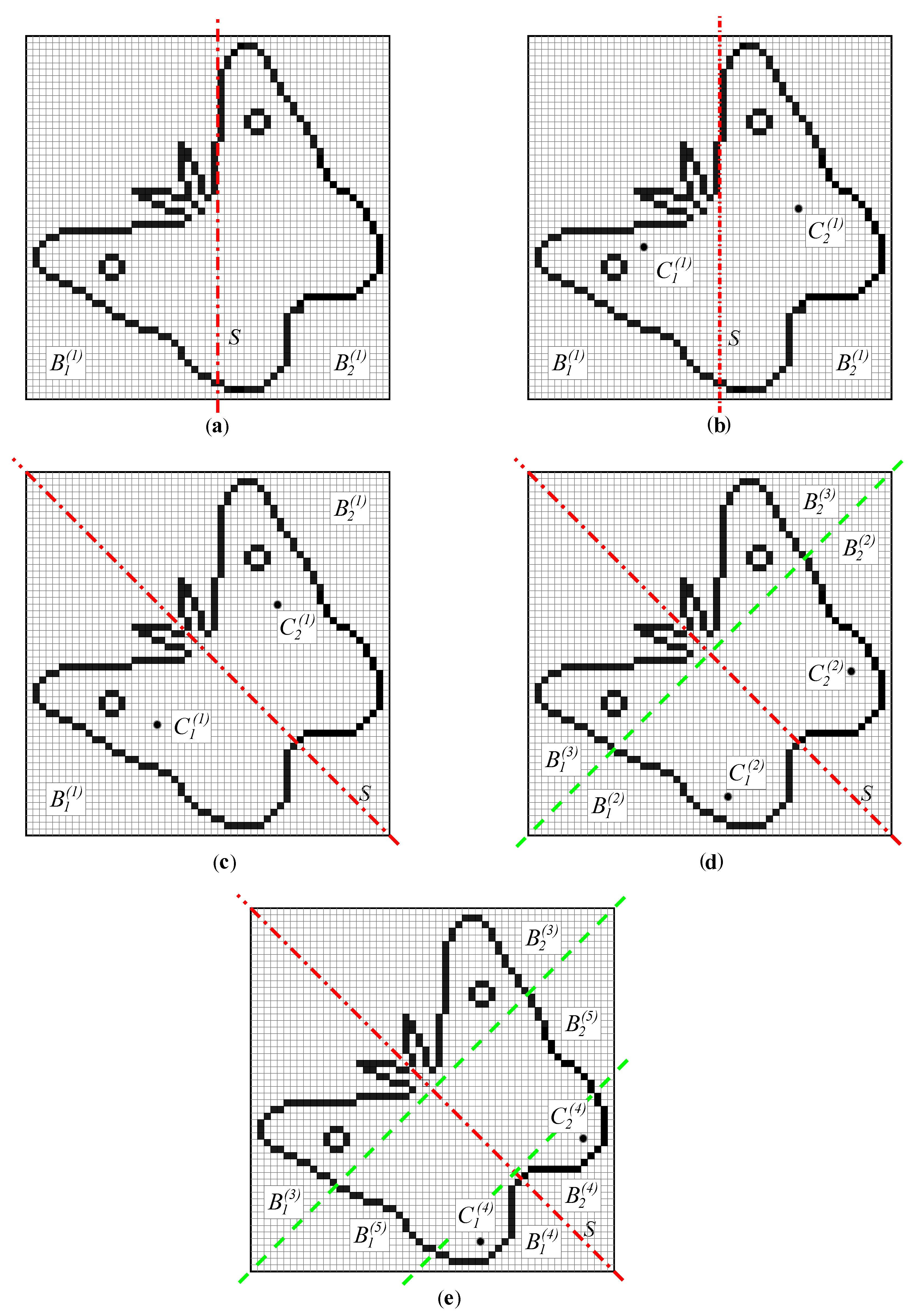
S divides B ( 1 ) into two subsets B 1 ( 1 ) an B 2 ( 1 ) , as seen in Figure 2a.
9.
A function SymmetryTest ( B ( i ) , B 1 ( i ) , B 2 ( i ) , S , δ ) is then used. This function calculates two auxiliary centroids C 1 ( i ) for B 1 ( i ) and C 2 ( i ) for B 2 ( i ) (Figure 2b shows an initial situation when i = 1 ). In addition, a common centroid C ( i ) for B 1 ( i ) and B 2 ( i ) is calculated according to (3). | B 1 ( i ) | and | B 2 ( i ) | represent the cardinalities of the corresponding sets. This part of the algorithm is hierarchically repeated as later described with the flowchart (Figure 3) and an example (Figure 4). In the first repetition, C ( i ) equals C ( 1 ) calculated in step 6.
C ( i ) = | B 1 ( i ) | C 1 ( i ) + | B 2 ( i ) | C 2 ( i ) | B 1 ( i ) | + | B 2 ( i ) | .
The function SymmetryTest returns either symmetric or non-symmetric. If the claims given in (4) are valid, the returned value is symmetric. The first claim states that the two centroids are equidistant from the testing axis/plane S. The second claim says that the line through the centroids is perpendicular to S, and the third claim checks whether the subsets B 1 ( i ) and B 2 ( i ) are balanced with respect to S, so that the common centroid is on S. All three conditions are necessary because they are independent of each other. Function d, as used in (4), calculates a non-negative distance between two points, or between a point and S.
| d ( C 1 ( i ) , S ) d ( C 2 ( i ) , S ) | δ | d ( C 1 ( i ) , S ) + d ( C 2 ( i ) , S ) d ( C 1 ( i ) , C 2 ( i ) ) | δ d ( C ( i ) , S ) δ .
The reflection symmetry is not confirmed in the situation shown in Figure 2b as relation (4) is not satisfied. The function SymmetryTest returns the value non-symmetric and the algorithm moves to step 11.
10.
Sets B 1 ( i ) and B 2 ( i ) are further split by the line/plane perpendicular to S. With each split, i is incremented. The function SymmetryTest is repeatedly called for a split pair of subsets until the threshold for the division is reached (a suitable threshold is 2 m, for example) or the function returns non-symmetric. If symmetric is returned in all runs of the SymmetryTest, the object is considered symmetric in the actual orientation, and the rotation angle (two angles in 3D) of the symmetry axis/plane is stored.
11.
S is rotated for a small angle α (e.g., α = 1 ° ) and the algorithm returns to step 9 if not all rotation positions have been checked yet. Otherwise, the algorithm verifies whether at least one angle was stored in the previous steps. The object is declared to be symmetric in this case, otherwise it is non-symmetric.
The situation displayed in Figure 2c is reached after some consecutive rotations of S. The algorithms continue with step 8 after each rotation. Set B ( 1 ) is divided into subsets B 1 ( 1 ) and B 2 ( 1 ) ; for them, the centroids are calculated, and the function SymmetryTest is invoked, which returns symmetric. Sets B 1 ( 1 ) and B 2 ( 1 ) are then split by the line perpendicular to S, and two pairs of subsets are obtained (in the concrete case shown in Figure 2d, the green line is perpendicular to S and two pairs of boundary sets are obtained ( B 1 ( 2 ) , B 2 ( 2 ) ) and ( B 1 ( 3 ) , B 2 ( 3 ) )). The process is repeated at first for the pair of sets B 1 ( 2 ) and B 2 ( 2 ) . The centroids C 1 ( 2 ) and C 2 ( 2 ) are calculated (see Figure 2d). As the function SymmetryTest returns symmetric, the sets are divided again. Figure 2e shows the next subdivision of the region indexed with i = 2 , i.e., containing B 1 ( 2 ) and B 2 ( 2 ) , into regions with i = 4 and i = 5 . Finally, the current rotation slope of the symmetry axis is stored as SymmetryTest=symmetric after all subdivisions. G is thus declared symmetric.
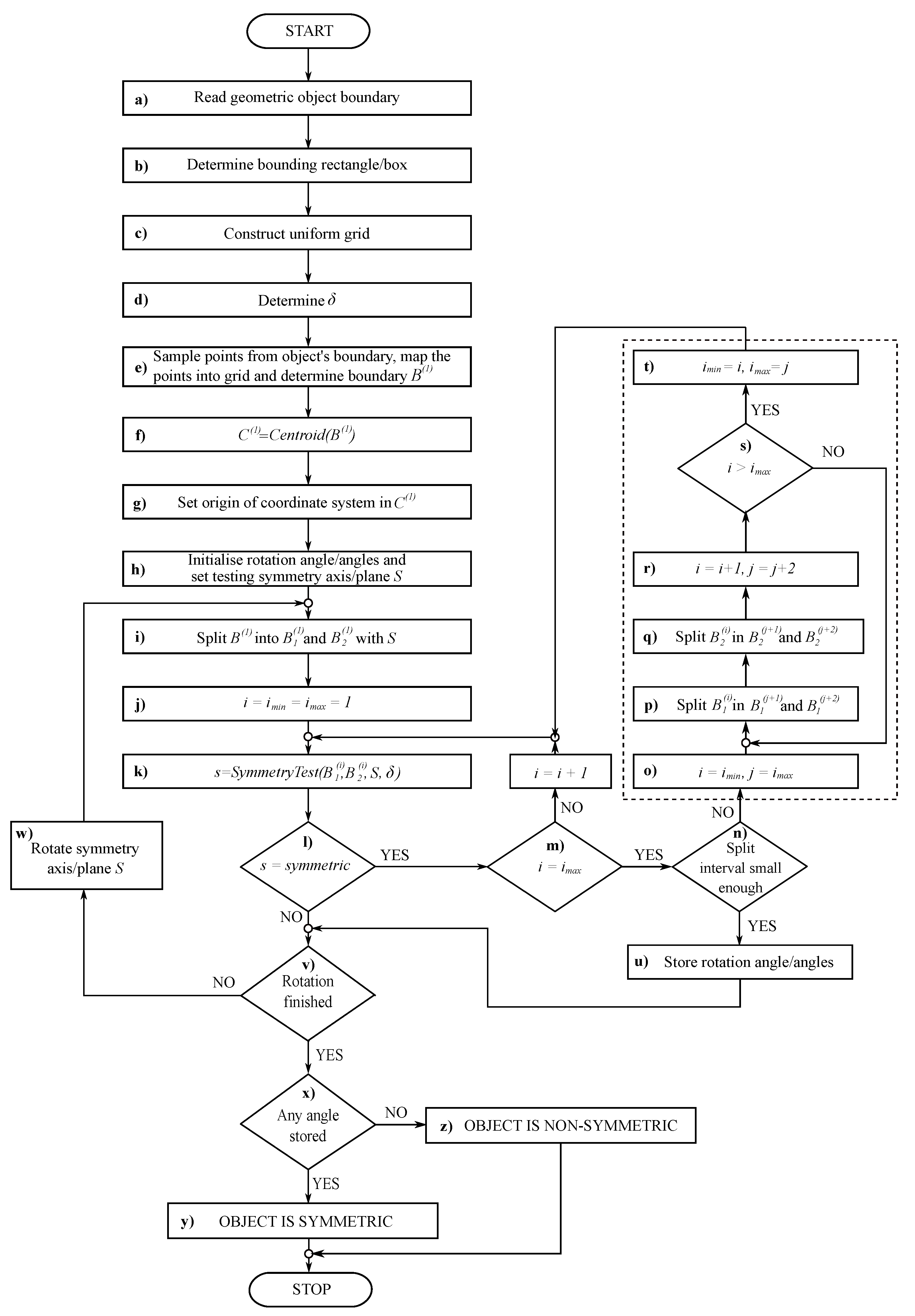
The flowchart of the proposed algorithm is shown in Figure 3. Its most demanding phase is analysed step by step through the example in the continuation.
Blocks ae of the flowchart correspond to the described steps 1–5, respectively. Blocks f and g represent step 6, and block h corresponds to step 7. At this point, the algorithm enters a loop in which the testing symmetry axis/plane S is gradually rotated (block w) and the symmetry is separately checked for each rotated position. Block i divides the set of the object’s boundary cells into two subsets on opposite sides of S (step 8), and block k then checks whether they are symmetric with respect to S (step 9).
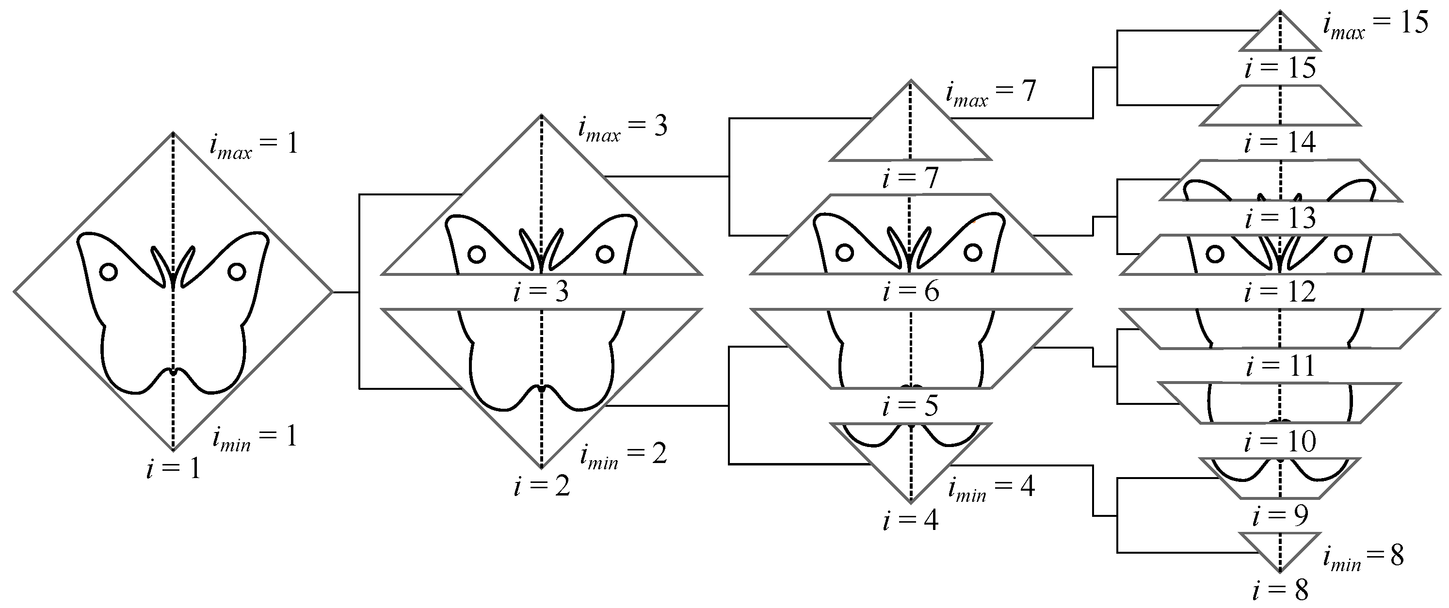
The symmetry test is performed hierarchically as the problem is gradually split into smaller sub-problems which are then subjected to the same testing procedure. The use of recursion allows for a straightforward easy-to-understand solution. The considered hierarchical process may be represented by a binary tree (see Figure 4), and the recursion in its common, stack-based form traverses this tree in a depth-first manner, which, however, does not completely follow the concept set out in the above step 10. On the other hand, the iterative algorithm from Figure 3 governs the splitting process and the order of performing the symmetry tests in a slightly complex way by the three loop control variables i, i m i n , i m a x , and auxiliary j, but it implements the breadth-first (level-order) traversal—BFT, which turned out to be more preferable for our purpose. If a considered object is symmetric, then both solutions lead to the same result, and a complete traversal to some predefined tree height is required in both cases. In the case of an asymmetric object, however, the depth-first traversal may unnecessarily probe to great depths the branches representing symmetrical parts even though the possibility of symmetry could be disproved at higher hierarchical levels by testing a few bigger split parts of the entire object only.
Let us explain the BFT operation in more detail using the example in Figure 4. Parts of the same example are already shown in Figure 2c–e where, however, the focus was on the positions of the centroids, while here we stress the role of the loop control variables. To make the presentation easier and clearer, the grid was removed, and the images were rotated by 45°. We will also use a slightly simplified terminology, as instead of talking about the splitting and testing sets of boundary cells, we will talk about splitting and testing the nodes that represent these sets.
Each tree level corresponds to a complete execution of the loop indicated by the termination condition in block m. The considered object (butterfly) is symmetric, so the loop is not exited at any tree level by an early termination condition in block l. Within the loop, i increases from i m i n to i m a x . The control is then transferred to the hatched block on the right side of Figure 3, where the next tree level is established by splitting each leaf node into two halves (step 10) and adjusting i m i n and i m a x accordingly. Note that the left and the right half of each node image are split separately in blocks p and q, respectively. The operations at each of the four levels of the considered example are illustrated in the continuation. For simplicity, a node with index i will be labelled N i .
  • Level 0 (root level). Block i sets both, i m i n and i m a x to 1 and initialises i = i m i n = 1 . After a single iteration, the loop termination condition in block m is true, and the hatched block is entered. Blocks p and q split the root node N 1 into N 2 and N 3 . The loop indicated by termination condition s is exited with i = 2 , i m a x = 1 , and j = 3 . Accordingly, block t sets i m i n = 2 and i m a x = 3 , making the next tree level ready for processing.
  • Level 1. Nodes N 2 and N 3 are both successfully tested for symmetry before the loop termination condition in block m becomes true. Blocks p and q within the loop in the hatched block split N 2 into the pair of nodes ( N 4 , N 5 ) and N 3 into ( N 6 , N 7 ). The loop is exited with i = 4 , i m a x = 3 , and j = 7 . Accordingly, block t sets i m i n = 4 and i m a x = 7 .
  • Level 2. Nodes N 4 N 7 are all successfully tested for symmetry before the loop termination condition in block m becomes true. Blocks p and q within the loop in the hatched block split N 4 into ( N 8 , N 9 ), N 5 into ( N 10 , N 11 ), N 6 into ( N 12 , N 13 ), and N 7 into ( N 14 , N 15 ). The loop is exited with i = 8 , i m a x = 7 , and j = 15 . Accordingly, block t sets i m i n = 8 and i m a x = 15 .
  • Level 3. Nodes N 8 N 15 are all successfully tested for symmetry before the loop termination condition in block m is true. This depends on the predefined splitting threshold tested in the loop termination condition n, whether the algorithm proceeds to the hatched block to split these nodes further or it terminates the symmetry test for the considered rotated position of S.
Obviously, blocks p and q always split node N i into N 2 i and N 2 i + 1 , which is, of course, an expected result for the complete binary tree (where each internal node has two children, and all leaves are at the same level). This suggests that we could dispose of not only of the auxiliary variable j, but also of i m i n and i m a x . However, we abandoned this modification as it prevents another more important adaptation: namely, the algorithm in its current form can easily be adapted to avoid extending empty nodes which do not contain any boundary cells. This can be done by embedding blocks p and q and the statement j = j + 2 from block r into an if clause, which checks the cardinalities of B 1 ( i ) and B 2 ( i ) before splitting.
The remaining blocks u–z of the flowchart in Figure 3 simply conclude the algorithm by performing the last step 11.
The proposed algorithm works for open or closed geometric shapes, and the latter can contain holes, which may even be nested. The algorithm can work in three modes with minor modifications:
Mode A:
All symmetry axes/planes in G are determined within the granularity α .
Mode B:
The first found symmetry axis/plane is returned.
Mode C:
The algorithm determines the closest axis/plane to the ideal symmetry axis/plane for non-symmetric G . It searches for S where the Euclidean distance between C 2 ( 1 ) and the mirrored image of C 1 ( 1 ) across S is the smallest.

3.1. Algorithm Acceleration

The algorithm presented in Figure 3 is generally quite slow, so speed-ups are needed to make it usable in practice and competitive with the existing methods. The algorithm processes the individual rotated positions of the object independently, splitting the set of boundary cells B ( 1 ) into B 1 ( 1 ) and B 2 ( 1 ) with respect to S in time O ( | B ( 1 ) | ) . After that, for each pair of B 1 ( i ) and B 2 ( i ) , starting with i = 1 , the algorithm sequentially:
1.
Computes the centroids of B 1 ( i ) , B 2 ( i ) , and B ( i ) = B 1 ( i ) B 2 ( i ) in time O ( | B ( i ) | ) .
2.
Evaluates inequality (4) in time O ( 1 ) .
3.
Splits B 1 ( i ) and B 2 ( i ) perpendicularly to S into two pairs of subsets in time O ( | B ( i ) | ) .
Let:
  • l be the number of hierarchical levels of execution of the algorithm.
  • l m a x indicate the maximum value of l.
  • i m i n ( h ) and i m a x ( h ) , 1 h l , be the start and end index i of B 1 ( i ) , B 2 ( i ) , and B ( i ) at level h.
  • α stand for the granularity of the slope increment of S.
  • D be the dimension ( D { 2 , 3 } ) .
  • Diagonal be the length of the diagonal of the bounding box int 3D or a bounding rectangle in 2D.
For each hierarchical level h:
i = i m i n ( h ) i m a x ( h ) | B 1 ( i ) | = | B 1 ( 1 ) | , i = i m i n ( h ) i m a x ( h ) | B 2 ( i ) | = | B 2 ( 1 ) | , and i = i m i n ( h ) i m a x ( h ) | B ( i ) | = | B ( 1 ) | .
As a consequence of (5), the total time complexity of computing centroids and subset splits at each hierarchical level h is O ( | B ( 1 ) | ) . This is also the total time complexity of all three listed operations for level h as the evaluations of (4) only require O ( i m a x ( h ) i m i n ( h ) + 1 ) time.
The maximum number of hierarchical levels l m a x is reached when splitting is performed to the threshold of 2 m (see Equation (1). Then, at the leaf level (see Figure 4), we have at most D i a g o n a l / ( 2 m ) subsets. A complete binary tree has 2 l m a x 1 nodes at the leaf level leading to (6):
2 l m a x 1 = D i a g o n a l 2 m .
This gives (7):
l m a x = log 2 D i a g o n a l m .
The upper bound of the processing time for each object position is, therefore, O ( | B ( 1 ) | log D i a g o n a l m ) . The number of all rotated positions is 180 α ( D 1 ) , and the worst-case time complexity of the algorithm from Figure 3 is described by (8).
T w o r s t = O 180 α ( D 1 ) | B ( 1 ) | log D i a g o n a l m .
D and Diagonal are of course part of the problem definition and cannot be changed. The logarithmic factor has the smallest impact on T w o r s t and besides this, the threshold 2 m affects the accuracy of the symmetry detection. Therefore, speed-ups must be primarily designed by increasing step α , or by downsampling B ( 1 ) , at least in the individual phases of the algorithm.

3.1.1. Dual-Resolution Grid

Two uniform grids in different scales are formed in the initialisation step: the rough U R and the coarse U. The density of the uniform grid is controlled by parameter r in (1); r = 1000 is used for constructing U and r = 100 for U R . G is initially embedded into both grids and two sets of boundary cells are obtained: B R from the U R and B from U. Certainly, | B R | | B | . The algorithm switches between both grids for each slope of the test axis/plane S in the following way:
  • It starts with B R , splits it into B R 1 and B R 2 , and runs SymmetryTest ( B R 1 , B R 2 , S , δ ) .
  • If the SymmetryTest returns symmetric, the algorithm switches to U and gradually considers the split sub-problems until SymmetryTest = non-symmetric or the subdivision threshold is reached.

3.1.2. Variable Granularity of the Testing Axis/Plane

Incrementing the slope of S for equal steps is time-consuming when S is far from symmetric. However, these steps can be made variable, as explained in the continuation.
Let C ¯ 1 ( 1 ) be a mirrored copy of C 1 ( 1 ) across S and let v c be a vector connecting C 2 ( 1 ) and C ¯ 1 ( 1 ) . Another vector v s is placed on S with the tail at the origin (see Figure 5). v s is a vector of length of m 2 initially pointing in the positive y direction, and rotates together with S. The line l (or the plane in 3D), perpendicular to v s and passing through the origin, divides the plane/space into two half-planes/half-spaces (l is plotted in Figure 5a). Its role is explained subsequently.
Let us suppose that S smoothly rotates around the origin. The length | v c | is reducing as S approaches the symmetric position. It becomes zero exactly at the symmetry, and when it leaves it, | v c | starts to increase again. Furthermore, after passing the symmetric position, v c changes the half-plane defined by v s .
We can therefore observe the sign s g obtained from the dot product of vectors v c and v s according to (9). When both vectors point in the same half-plane, s g is positive, it is otherwise negative. If | v c | is zero, then s g is also zero.
s g = s g n ( v c · v s )
Checking the sign s g appears useful for the detection of whether the symmetric position has been overlooked. However, two questions should be investigated:
  • Does observing s g prevent false positives?
  • Does observing s g prevent false negatives?
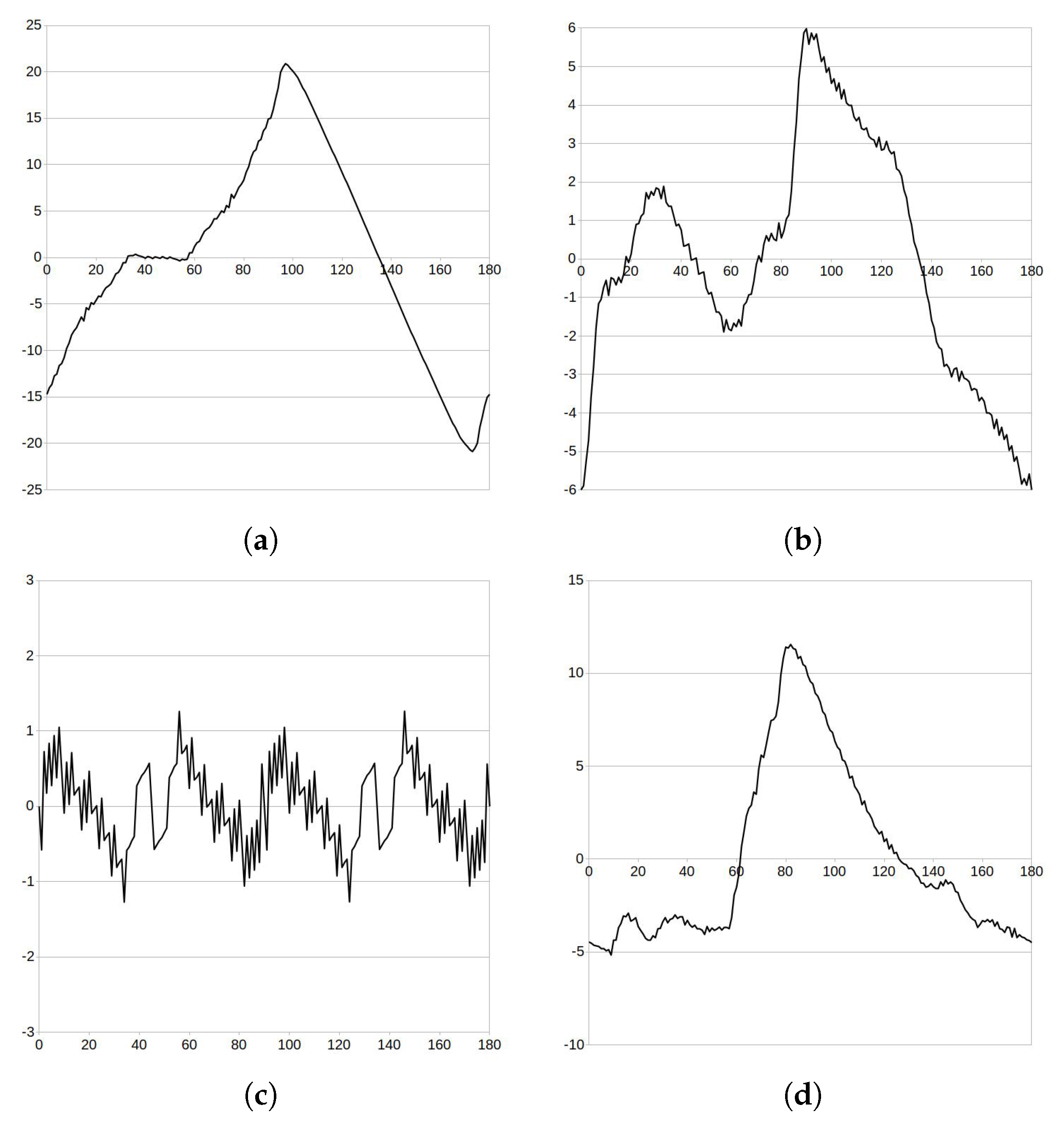
The answers are obtained by considering Figure 6, where curves show the signed length s L of v c , defined in (10).
s L = s g | v c | .
First of all, it can be observed that the curves s L are not smooth but only have C 0 continuity. The reason for this is the introduction of the uniform subdivision in the initialisation phase of the algorithm. In addition to the noticeable rounding errors (e.g., the v c of the circle is not zero in Figure 5c) which causes the unsmooth change of s L even if S moved fluently. For example, the sign s g changes 12 times for the object glass and 9 times for the object butterfly (see Figure 6a,b), indicating 12 and 9 possible symmetric positions, although only 1 exists in both objects, as we see in Figure 5. Furthermore, s L for the non-symmetric object hand indicates two symmetric positions. Obviously, observing just s g is not resistive to false positives. However, they can easily be refused by applying the algorithm from Figure 3 to zones where the changes of s g are detected.
Let us observe Figure 6c, showing s L for the object circle. The s L should be zero all the time as the circle has infinite symmetries. Unfortunately, due to the already described uniform subdivision effect, s L also only has in this case C 0 continuity. This, however, can also lead to the false negative scenario. For example, if the slopes of S at 22° and 67° are tested after each other, they both give the positive sign s g , which leads to the conclusion that there is no symmetric scenario in between. This is the reason why just observing the sign s g is not enough. However, Figure 6 shows that the dangerous situation for the false negatives only appears for small values of s L . Therefore, we consider both the sign s g and the length s L . As the cell in the uniform subdivision is of size m, the iteration of the algorithm from Figure 3 for the corresponding rotation of S is executed when | s L | < 2 m .
The situation in 3D is identical with only one difference; vector v s defines the half-space.

3.1.3. Parallelisation

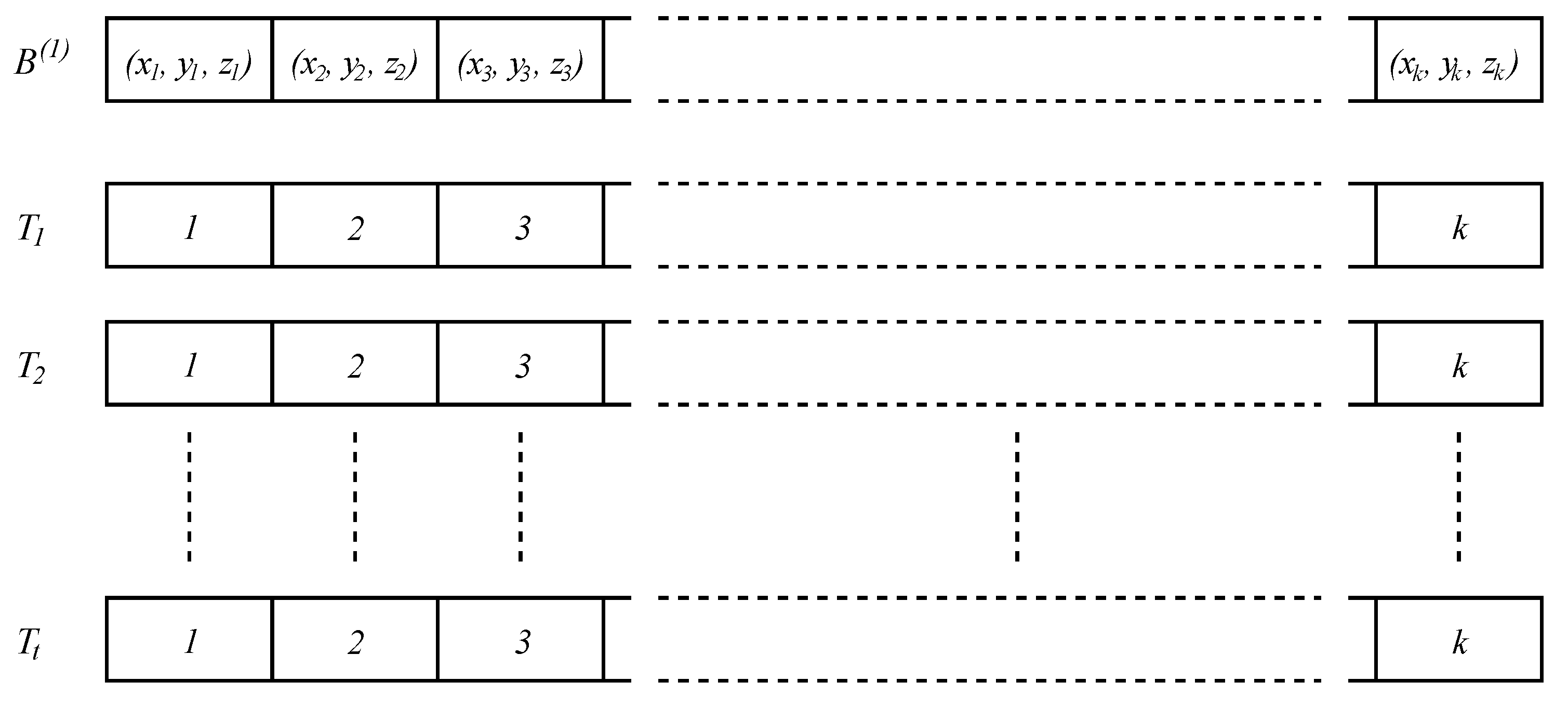
The presented algorithm, either in its basic or accelerated form with the dual-resolution grid and/or variable granularity techniques, changes the slope of the testing axis/plane and repeats the same calculations independently, which is ideal for parallel processing. Figure 7 shows the adaptation of data for this purpose. Boundary cells’ coordinates B ( 1 ) are stored in an array. Each thread T τ , 1 τ t , where t is the number of available threads has its own array of indices, pointing into the array with the boundary cells B ( 1 ) . Each thread then processes its own candidate for the symmetry axis/plane. Splits of cells by S are not performed on the B ( 1 ) array, but on the corresponding arrays of indices. Two instances of the represented data structures, each representing the specific grid, are used in the case of the dual-resolution grid. OpenMP [47] was used for parallel implementation.

4. Results

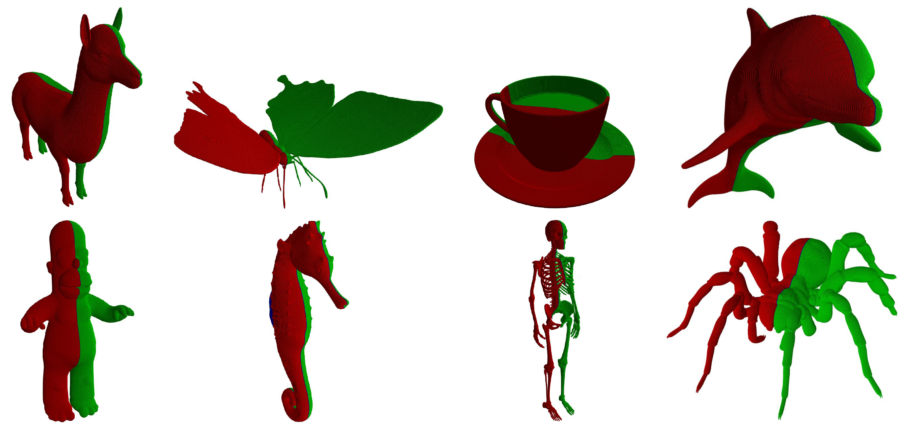
The proposed algorithm [48] for reflection symmetry detection was intensively tested on a large number of 3D objects obtained from [49,50,51], 20 of which are considered in detail in this section. They are shown in Figure 8, while details about their properties, important for our algorithm, are given in Table 1. All objects were first tested in Mode A where the algorithm classified the twelve objects as symmetric, four of which have more than one symmetric plane, while the remaining eight objects were marked as non-symmetric. The results of the algorithm for symmetric objects with only one symmetric plane are shown in Figure 9. Figure 10 gives the results for the objects trophy (two symmetries), ornate frame (six symmetries, but only three are shown), and rugby ball (with infinitely many symmetric positions, but only three are shown). The object apple, also with infinitely many symmetric positions, is not shown. Mode C was then used on the objects declared as non-symmetric to find the nearest symmetry plane for each of them. The results are shown in Figure 11. The obtained nearest symmetry planes were compared with the algorithm proposed by Hruda et al. [27] and an adequate correspondence was obtained.
The algorithm’s computational efficiency was finally tested. The average spent CPU times of 10 runs are given in Table 2. The algorithm was tested in a single thread while running in Mode A (i.e., when all possible symmetry planes were determined), or Mode C, when the nearest S was searched for. The direct implementation of the algorithm from Figure 3, named basic, was tested first. As expected (see the explanation at the beginning of Section 3.1), the run-time depends on the number of boundary cells B ( 1 ) used to represent the geometric object and the number of symmetry planes. Without a doubt, the basic approach is slow. However, applying the acceleration techniques, including the rough/coarse grids and the variable granularity of testing slopes, significantly changes the situation (see the column accelerated under single thread in Table 2). The acceleration is drastic in comparison to the basic algorithm.
The parallel version of the algorithm was finally used. This time the proposed approach was faced against the parallel version of the algorithm published in 2022 by Hruda et al. [27] (considered as referenced in Table 2). Both algorithms (the proposed one and the referenced one) were run on the same personal computer with an AMD Ryzen 9 5900X processor with 12 cores and 24 threads. The computer had 64 GB RAM. The tests were executed on a Linux KUbuntu 21.10 (Kernel 5.13.0-30). As can be seen from the results, the proposed algorithm was faster in all testing cases.
A parametric surface generated by the SURFMOD application [52] was used to demonstrate the universality of the algorithm. The surface shown in Figure 12a was sampled and the obtained points were mapped onto | B ( 1 ) | = 624,538 voxels. The surface has four global reflection symmetries, two of them are shown in Figure 12b,c. The basic single thread version of the algorithm took 129.06 s, while the Accelerated one terminated in just 0.321 s. The multi-threaded version was considerably faster: the basic version took 9.56 s, the accelerated version took 0.035 s, and the referenced algorithm required 0.381 s.

5. Discussion

Humans (and even some animals) consider symmetric objects as natural and beautiful [53], and therefore the symmetry has been considered from many various aspects. However, computers do not have the ability to see and to estimate symmetry. Various approaches to this task were suggested in the past, and these were reviewed in Section 2 of this paper. Section 3 introduced the new hierarchical approach for global reflection symmetry detection. This basic approach, however, makes the algorithm extremely general, as it works for 2D or 3D geometric objects, which can be closed or not and may also containing holes or not. Unfortunately, the direct implementation of the basic algorithm turns out to be slow, as shown in Table 2. Therefore, three acceleration techniques were introduced in this paper. The first one uses the dual-resolution grid, while the second one uses the variable granularity of rotating the testing axis/plane. Table 2 confirms that the acceleration is dramatic, and achieves almost a factor of 1000. For geometric objects represented by more than 1,000,000 boundary cells, the algorithm found the position of the symmetry plane in less than half a second in all the testing cases. The proposed algorithm was then parallelised and an additional reduction in CPU time was achieved in this way. The algorithm was compared with the state-of-the-art and achieved the same results with a shorter CPU time.
Future work will go in two directions. Firstly, additional acceleration techniques will be considered, and secondly, finding the symmetries in voxel-based data will be investigated for medical applications.

Author Contributions

Conceptualisation, B.Ž. and D.P.; methodology, D.S. and N.L.; software, A.N. and Š.K.; validation, I.K. and A.N.; formal analysis, D.P. and I.K.; investigation, B.Ž., D.P., I.K. and A.N.; resources, I.K.; data curation, Š.K.; writing—original draft preparation, B.Ž., D.P. and A.N.; writing—review and editing, D.S., I.K., Š.K. and N.L.; visualisation, A.N.; supervision, I.K. and B.Ž.; project administration, I.K. and D.P.; funding acquisition, I.K. All authors have read and agreed to the published version of the manuscript.

Funding

This research was funded by the Slovene Research Agency under Research Project N2-0181 and Research Programme P2-0041, and the Czech Science Foundation under Research Project 21-08009K.

Institutional Review Board Statement

Not applicable.

Informed Consent Statement

Not applicable.

Data Availability Statement

Not applicable.

Conflicts of Interest

The authors declare no conflict of interest.

References

  1. McManus, I.C. Symmetry and Asymmetry in Aesthetics and the Arts. Eur. Rev. 2005, 13, 157–180. [Google Scholar] [CrossRef]
  2. Mehaffy, M.W. The Impacts of Symmetry in Architecture and Urbanism: Toward a New Research Agenda. Buildings 2020, 10, 249. [Google Scholar] [CrossRef]
  3. Evans, C.S.; Wenderoth, P.; Cheng, K. Detection of Bilateral Symmetry in Complex Biological Images. Perception 2000, 29, 31–42. [Google Scholar] [CrossRef]
  4. Qui, W.; Yuan, J.; Ukwatta, E.; Sun, Y.; Rajchl, M.; Fenster, A. Prostate Segmentation: An Efficient Convex Optimization Approach With Axial Symmetry Using 3-D TRUS and MR Images. IEEE Trans. Med. Imaging 2014, 33, 947–960. [Google Scholar]
  5. Jäntschi, L.; Bolboacã, S.D. Symmetry in Applied Mathematics; MDPI: Basel, Switzerland, 2020. [Google Scholar]
  6. Glowacz, A.; Królczyk, G.; Antonino-Daviu, J.A. Symmetry in Mechanical Engineering; MDPI: Basel, Switzerland, 2020. [Google Scholar]
  7. Modrea, A.; Munteanu, V.M.; Pruncu, I. Using the Symmetries in the Civil Engineering. An overview. Procedia Manuf. 2020, 46, 906–913. [Google Scholar] [CrossRef]
  8. Montoya, F.G.; Navarro, R.B. Symmetry in Engineering Sciences; MDPI: Basel, Switzerland, 2019. [Google Scholar]
  9. Weyl, H. Symmetry; Princenton University Press: New York, NY, USA, 1952. [Google Scholar]
  10. Miller, W. Symmetry Groups and Their Applications; Academic Press: London, UK, 1972. [Google Scholar]
  11. Liu, X.; Hel-Or, H.; Kaplan, C.S.; van Gool, L. Computational Symmetry in Computer Vision and Computer Graphics. Found. Trends Comput. Graph. Vis. 2009, 5, 1–195. [Google Scholar] [CrossRef]
  12. Martin, G.E. Transformation Geometry; Springer: New York, NY, USA, 1982. [Google Scholar]
  13. Barker, W.H.; Howe, R. Continuous Symmetry: From Euclid to Klein; American Mathematical Society: Providence, RI, USA, 2007. [Google Scholar]
  14. Leyton, M. Symmetry, Causality, Mind; MIT Press: Cambridge, MA, USA, 1992. [Google Scholar]
  15. Ponce, J. On Characterizing Ribbons and Finding Skewed Symmetries. Comput. Vis. Graph. Image Process. 1990, 52, 328–340. [Google Scholar] [CrossRef]
  16. Conners, R.W.; Ng, C.T. Developing a Quantitative Model of Human Preattentive Vision. IEEE Trans. Syst. Man Cybernet. 1989, 19, 1384–1407. [Google Scholar] [CrossRef]
  17. Tyler, C.W. Human Symmetry Perception and its Computational Analysis; Lawrence Erlbaum Associates: Mahwah, NJ, USA, 2002. [Google Scholar]
  18. Xiao, Z.; Wu, J. Analysis on Image Symmetry Detection Algorithms. In Proceedings of the Fourth International Conference on Fuzzy Systems and Knowledge Discovery (FSKD 2007), Haikou, China, 24–27 August 2007; pp. 745–750. [Google Scholar]
  19. Mitra, N.J.; Pauly, M.; Wand, M.; Ceylan, D. Symmetry in 3D geometry: Extraction and applications. Comput. Graph. Forum 2013, 32, 1–23. [Google Scholar] [CrossRef]
  20. Bartalucci, C.; Furferi, R.; Governi, L.; Volpe, Y. A Survey of Methods for Symmetry Detection on 3D High Point Density Models in Biomedicine. Symmetry 2018, 10, 263. [Google Scholar] [CrossRef] [Green Version]
  21. Elawady, M.; Ducottet, C.; Alata, O.; Barat, C.; Colantoni, P. Wavelet-Based Reflection Symmetry Detection via Textural and Color Histograms: Algorithm and Results. In Proceedings of the 2017 IEEE International Conference on Computer Vision Workshops (ICCVW), Venice, Italy, 22–29 October 2017; pp. 1734–1738. [Google Scholar]
  22. Chen, H.; Wang, L.; Zhang, Y.; Wang, C. Dominant Symmetry Plane Detection for Point-Based 3D Models. Adv. Multimed. 2020, 2020, 8861367. [Google Scholar]
  23. Schiebener, D.; Schmidt, A.; Vahrenkamp, N.; Asfour, T. Heuristic 3D Object Shape Completion Based on Symmetry and Scene Context. In Proceedings of the IEEE/RSJ International Conference on Intelligent Robots and Systems (IROS), Daejeon, Korea, 9–14 October 2016; pp. 74–81. [Google Scholar]
  24. Combés, B.; Hennessy, R.; Waddington, J.; Roberts, N.; Prima, S. Automatic Symmetry Plane Estimation of Bilateral Objects in Point Clouds. In Proceedings of the IEEE Conference on Computer Vision and Pattern Recognition, Anchorage, AK, USA, 23–28 August 2008; pp. 1–8. [Google Scholar]
  25. Ecins, A.; Fermüller, C.; Aloimonos, Y. Detecting Reflectional Symmetries in 3D Data Through Symmetrical Fitting. In Proceedings of the IEEE International Conference on Computer Vision Workshops (ICCVW), Venice, Italy, 22–29 October 2017; pp. 1779–1783. [Google Scholar]
  26. Nagar, R.; Raman, S. Detecting Approximate Reflection Symmetry in a Point Set Using Optimization on Manifold. IEEE Trans. Signal Process. 2019, 67, 1582–1595. [Google Scholar] [CrossRef] [Green Version]
  27. Hruda, L.; Kolingerová, I.; Váša, L. Robust, Fast, Flexible Symmetry Plane Detection Based on Differentiable Symmetry Measure. Vis. Comput. 2022, 38, 555–571. [Google Scholar] [CrossRef]
  28. Li, B.; Johan, H.; Ye, Y.; Lu, Y. Efficient 3D Reflection Symmetry Detection: A View-based Approach. Graph. Models 2016, 83, 2–14. [Google Scholar] [CrossRef]
  29. Sipiran, I.; Gregor, R.; Schreck, T. Approximate Symmetry Detection in Partial 3D Meshes. Comput. Graph. Forum 2014, 33, 131–140. [Google Scholar] [CrossRef] [Green Version]
  30. Kakarala, R.; Kaliamoorthi, P.; Premachandran, V. Three-Dimensional Bilateral Symmetry Plane Estimation in the Phase Domain. In Proceedings of the IEEE Conference on Computer Vision and Pattern Recognition, Portland, OR, USA, 23–28 June 2013; pp. 249–256. [Google Scholar]
  31. Podolak, J.; Shilane, P.; Golovinsky, A.; Rusinkiewiczm, S.; Funkhouser, T. A Planar-Reflective Symmetry Transform for 3D Shapes. ACM Trans. Graph. 2006, 25, 549–559. [Google Scholar] [CrossRef]
  32. Cicconet, M.; Hildebrand, D.G.C.; Elliott, H. Finding Mirror Symmetry via Registration and Optimal Symmetric Pairwise Assignment of Curves: Algorithm and Results. In Proceedings of the IEEE International Conference on Computer Vision Workshops (ICCVW), Venice, Italy, 22–29 October 2017; pp. 1759–1763. [Google Scholar]
  33. Simari, P.D.; Kalogerakis, E.; Singh, K. Folding meshes: Hierarchical Mesh Segmentation Based on Planar Symmetry. In Proceedings of the Fourth Eurographics Symposium on Geometry Processing, Cagliary, Italy, 26–28 June 2006; pp. 111–119. [Google Scholar]
  34. Cailliere, D.; Denis, F.; Pele, D.; Baskurt, A. 3D Mirror Symmetry Detection Using Hough Transform. In Proceedings of the 5th IEEE International Conference on Image Processing, San Diego, CA, USA, 12–15 October 2008; pp. 1772–1775. [Google Scholar]
  35. Speciale, P.; Oswald, M.R.; Cohen, A.; Pollefeys, M. A Symmetry Prior for Convex Variational 3D Reconstruction. In Computer Vision—ECCV 2016; Leibe, B., Matas, J., Sebe, N., Welling, M., Eds.; Lecture Notes in Computer Science 9912; Springer: Cham, Germany, 2016; pp. 313–328. [Google Scholar]
  36. Liu, Y.-K.; Žalik, B.; Wang, P.-J.; Podgorelec, D. Directional Difference Chain Codes with Quasi-Lossless Compression and Run-Length Encoding. Signal Process. Image Commun. 2012, 27, 973–984. [Google Scholar] [CrossRef]
  37. Bribiesca, E. A Measure of Tortuosity Based on Chain Coding. Pattern Recognit. 2013, 46, 716–724. [Google Scholar] [CrossRef]
  38. Alvarado-Gonzalez, M.; Aguilar, W.; Garduño, E.; Velarde, C.; Bribiesca, E.; Medina-Bañuelos, V. Mirror Symmetry Detection in Curves Represented by Means of the Slope Chain Code. Pattern Recognit. 2019, 87, 67–79. [Google Scholar] [CrossRef]
  39. Aguilar, W.; Alvarado-Gonzalez, M.; Garduño, E.; Velarde, C.; Bribiesca, E. Detection of Rotational Symmetry in Curves Represented by the Slope Chain Code. Pattern Recognit. 2020, 107, 107421. [Google Scholar] [CrossRef]
  40. Sun, C.; Sherrah, J. 3D Symmetry Detection Using the Extended Gaussian Image. IEEE Trans. Pattern Anal. 1997, 19, 164–168. [Google Scholar]
  41. Korman, S.; Litman, R.; Avidan, S.; Bronstein, A. Probably Approximately Symmetric: Fast Rigid Symmetry Detection with Global Guarantees. Comput. Graph. Forum 2015, 34, 2–13. [Google Scholar] [CrossRef] [Green Version]
  42. Mitra, N.J.; Guibas, L.J.; Pauly, M. Approximate Symmetry Detection for 3D Geometry. ACM Trans. Graph. 2006, 25, 560–668. [Google Scholar] [CrossRef]
  43. Ji, P.; Liu, X. A Fast and Efficient 3D Reflection Symmetry Detector Based on Neural Networks. Multimed. Tools Appl. 2019, 78, 35471–35492. [Google Scholar] [CrossRef]
  44. Wu, Z.; Jiang, H.; He, S. Symmetry Detection of Occluded Point Cloud Using Deep Learning. Procedia Comput. Sci. 2021, 183, 32–39. [Google Scholar] [CrossRef]
  45. Gao, L.; Zhang, L.-X.; Meng, H.-Y.; Ren, Y.-H.; Lai, Y.-K.; Kobbelt, L. PRS-Net: Planar Reflective Symmetry Detection Net for 3D Models. IEEE Trans. Vis. Comput. Graph. 2021, 27, 3007–3018. [Google Scholar] [CrossRef]
  46. Tsogkas, S.; Kokkinos, I. Learning-based Symmetry Detection in Natural Images. In Computer Vision—ECCV 2012 Florence; Fitzgibbon, A., Lazebnik, S., Perona, P., Sato, Y., Schmid, C., Eds.; Lecture Notes in Computer Science 7578; Springer: Berlin/Heidelberg, Germany, 2012; pp. 41–54. [Google Scholar]
  47. Mattson, T.G.; He, Y.; Koniges, A.E. The OpenMP Commom Core, Making OpenMP Simple Again; MIT Press: Cambridge, MA, USA; London, UK, 2019. [Google Scholar]
  48. Generalized Symmetries and Equivalences of Geometric Data. Supplementary Material. Available online: https://gemma.feri.um.si/projects/international-projects/generalized-symmetries-and-equivalences-of-geometric-data-si/eng/software-eng/ (accessed on 11 April 2022).
  49. PLY Files an ASCII Polygon Format. Available online: https://people.sc.fsu.edu/~jburkardt/data/ply/ply.html (accessed on 24 February 2022).
  50. The Stanford 3D Scanning Repository. Available online: http://graphics.stanford.edu/data/3Dscanrep/ (accessed on 24 February 2022).
  51. MS Paint3D Library. Available online: https://free3d.com/3d-model (accessed on 24 February 2022).
  52. Guid, N.; Kolmanič, S.; Strnad, D. SURFMOD: Teaching tool for parametric curve and surface methods in CAGD based on comparison and analysis. IEEE Trans. Educ. 2006, 49, 292–301. [Google Scholar] [CrossRef]
  53. Moller, A.P. Swallows and Scorpionflies Find Symmetry is Beautiful. Science 1992, 257, 327–328. [Google Scholar]
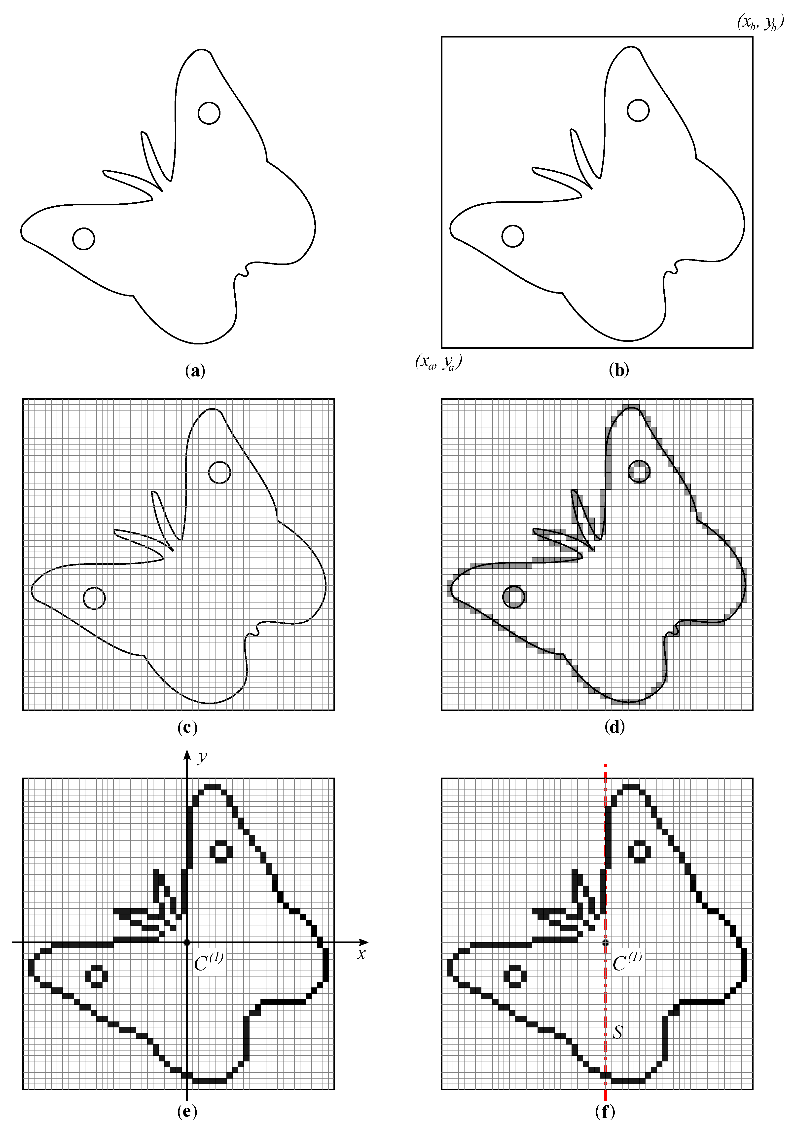
Figure 1. Steps of the proposed algorithm—part 1: (a) object boundary; (b) axis-aligned bounding rectangle/box determination; (c) uniform grid creation; (d) determination of the object’s boundary grid cells; (e) determining the centroid of the boundary cells and establishing the coordinate system; and (f) placing the initial testing symmetry axis/plane.
Symmetry 14 01060 g001
Figure 2. Steps of the proposed algorithm—continuation: (a) dividing boundary cells according to S; (b) calculating the centroids of divided cells; (c) rotating the S; (d) further dividing the sets of the boundary cells and calculating centroids for the new subsets; and (e) applying breadth-first traversal to further divide the sets of boundary cells.
Symmetry 14 01060 g002
Figure 3. Flowchart of the proposed algorithm for reflection symmetry detection.
Symmetry 14 01060 g003
Figure 4. Example of performing a symmetry test on gradually split segments in breadth-first order.
Symmetry 14 01060 g004
Figure 5. Four rasterised shapes: (a) glass; (b) butterfly; (c) circle; and (d) hand—to demonstrate variable granularity.
Symmetry 14 01060 g005
Figure 6. Graph of the signed distances s L with respect to the slope of S for (a) glass; (b) butterfly; (c) circle; and (d) hand.
Symmetry 14 01060 g006
Figure 7. Organisation of data for parallel execution.
Symmetry 14 01060 g007
Figure 8. Tested geometric objects.
Symmetry 14 01060 g008
Figure 9. Result of the algorithms: symmetric objects with a single plane of symmetry.
Symmetry 14 01060 g009
Figure 10. Result of the algorithms: some objects with multiple symmetries.
Symmetry 14 01060 g010
Figure 11. Result of the algorithms: the nearest symmetry plane for non-symmetric objects.
Symmetry 14 01060 g011
Figure 12. An application of the algorithm on the parametric surface: (a) the surface with shown control mesh; (b,c) found global reflection symmetries.
Symmetry 14 01060 g012
Table 1. Information about geometric objects used in the experiments.
Object | B ( 1 ) | Symmetric?
Alpaca1,322,413
Apple1,898,806✓✓
Astronaut2,381,281×
Buddha1,815,195×
Butterfly1,602,828
Coffee cup3,717,007
Dolphin836,102
Female bust1,703,742×
Flamingo431,892×
Homer1,234,423
Kangaroo836,738×
Male bust2,035,006×
Ornate frame1,304,854✓✓
Race car 13,490,257×
Race car 22,908,840×
Rugby ball951,947✓✓
Seahorse709,877
Skeleton560,303
Spider1,374,073
Trophy3,369,891✓✓
✓: symmetric; ✓✓: multiply symmetric; ×: non-symmetric.
Table 2. CPU times in seconds by applying different algorithms.
ObjectSingle ThreadMulti-Threaded
BasicAcceleratedBasicAcceleratedReferenced
Alpaca299.150.37428.030.0440.230
Apple424.500.43042.270.1510.193
Astronaut267.210.59252.890.0770.254
Buddha407.900.56440.240.1330.431
Butterfly353.860.36036.190.0460.167
Coffee cup839.880.42684.380.0790.187
Dolphin180.640.19512.880.0440.245
Female bust376.640.34537.510.0450.205
Flamingo94.180.1236.690.0470.418
Homer272.520.37624.760.0530.212
Kangaroo178.290.29213.010.1220.240
Male bust458.270.49545.070.0700.201
Ornate frame285.330.34127.760.0940.164
Race car 1800.701.02578.670.1230.208
Race car 2663.490.85065.490.0970.215
Rugby ball208.030.23515.210.0960.222
Seahorse149.600.14211.040.0340.308
Skeleton117.730.0678.660.0210.302
Spider312.450.40330.120.0480.199
Trophy755.170.60875.770.0900.202
Publisher’s Note: MDPI stays neutral with regard to jurisdictional claims in published maps and institutional affiliations.