Article

Scattering Properties of an Acoustic Anti-Parity-Time-Symmetric System and Related Fabry–Perot Resonance Mode

1
School of Electrical and Information Engineering, Changzhou Institute of Technology, Changzhou 213032, China
2
MOE Key Laboratory of Modern Acoustics, Nanjing University, Nanjing 210093, China
3
School of Aviation and Mechanical Engineering, Changzhou Institute of Technology, Changzhou 213032, China
4
Key Laboratory of Architectural Acoustic Environment of Anhui Higher Education Institutes, Anhui Jianzhu University, Hefei 230601, China
*
Authors to whom correspondence should be addressed.
Symmetry 2022, 14(5), 965; https://doi.org/10.3390/sym14050965
Submission received: 24 March 2022 / Revised: 29 April 2022 / Accepted: 6 May 2022 / Published: 9 May 2022
(This article belongs to the Section Physics)

Abstract

:
The pursuit of artificial structures exhibiting unusual acoustic properties is a major scientific endeavor, in which anti-parity-time ( PT ) symmetry has been coming into view recent years. At the same time, with the emergence of new acoustic metamaterials, the classical Fabry–Perot resonance mode also exhibits fascinating scattering features similar to those of the anti- PT -symmetric system. We derive the generalized relation for the scattering parameters of an acoustic anti- PT -symmetric system with a transfer matrix, including conjugate bidirectional reflection coefficients and pure real feature of transmission coefficient. In the absence of the real or the imaginary (representing gain/loss) part of the refractive index, the anti- PT -symmetric system degrades into a pair of complementary media, resulting in the bidirectional total transmission. Moreover, a Fabry–Perot resonance mode exhibiting conjugate bidirectional reflection coefficients and a pure imaginary transmission coefficient has been demonstrated. Our results are meaningful for guiding the experimental test of an acoustic anti- PT -symmetric system and the design of associated bidirectional response prototype devices.

1. Introduction

Since the discovery of non-Hermitian Hamiltonian H that commute with the PT operator, a property that can lead to real-energy eigenvalues [1,2,3], intriguing developments in quantum mechanics have been made in recent years. Owing to the analogy between the Schrödinger equation in quantum mechanics and the classical wave equation, the concept of PT symmetry was further introduced into photonics [4,5,6,7,8,9] and acoustics [10,11,12,13,14,15,16,17]. By utilizing balanced gain and loss satisfying n ( x ) = n * ( x ) , many intriguing acoustic phenomena and applications have been predicted and observed, such as acoustic cloaks [10], invisible sensors [11,12], flexible control of exceptional points [13], unidirectional transparency [14], tunability of piezoelectric semiconductors [15,16] and periodic PT -symmetric structures [17]. Additionally, while the stringent loss–gain balance can be circumvented by implementing unbalanced loss-only structures [18,19], the absence of gain gives rise to the intrinsic loss of overall energy.
Recently, another closely related striking symmetry, known as anti- PT symmetry, broadened the family of non-Hermitian symmetries [20,21,22,23,24,25,26,27,28,29]. Since it requires either gain or loss, the anti- PT symmetry had been demonstrated based on positive and negative index materials [20], nonlinear structure [21], flying atom beams [22], electrical circuit resonators [23], multiwaveguide systems [26], hybrid PT and anti- PT symmetry [27], and optical fibre [28]. Such systems lead to various intriguing effects, such as continuous lasing spectrum [20], energy difference conserving dynamics [23], coherent switch [24], and highly tunable Fano resonances [27]. However, due to the lack of efficient experimental methodology, the acoustic anti- PT -symmetric system has not been implemented yet, either theoretically or experimentally. On the other hand, metamaterials have been widely demonstrated to control acoustic waves, but previous efforts were mostly based on modulating the real parts of the constitutive parameters [30,31,32,33,34]. The acoustic anti- PT -symmetric structure, if it is realized based on metamaterials, may extend the study of metamaterials into the realm of complex constitutive parameters.
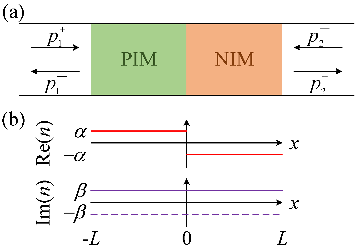
In this paper, we propose a synthetic system bridging positive-index material (PIM), negative-index material (NIM), and PT -symmetric acoustics. Their refractive index is anti-symmetric under combined PT operations, i.e., n ( x ) = n * ( x ) , with balanced PIM and NIM. In addition, we require that the mass density satisfies ρ ( x ) = ρ ( x ) [20]. The imaginary part of n ( x ) is symmetric, and can be positive (loss), negative (gain), zero, or any complicated spatial function. We found that they can display intriguing features, such as conjugate bidirectional reflection coefficients and pure real transmission coefficient, spontaneous phase transition of the scattering matrix, and a flat total transmission band. Subsequently, we further expand the scattering properties of the anti- PT -symmetric system and design a Fabry–Perot resonance mode with conjugate bidirectional reflection coefficients but pure imaginary transmission coefficient. Note that this Fabry–Perot resonance mode and classical anti- PT -symmetric system are comparatively different, no matter the geometric structure or the implementation method, and they are related to each other only through scattering properties. Our results, comprising conjugate bidirectional reflection coefficients and pure real/imaginary transmission coefficient are expected to have a huge application advantage in the virtual imaging and stealth of acoustic waves.

2. Generalized Relation

We generally begin with the scattering matrix S, which can be defined by [14]
p 1 p 2 + = S p 1 + p 2 r L t t r R p 1 + p 2 ,
where p 1 , 2 + and p 1 , 2 represent the sound pressure spreading along the forward and backward direction, respectively, with the subscript 1 (2) denoting the PIM (NIM) side, as illustrated in Figure 1a. r L ( r R ) is the reflection coefficient from the PIM (NIM) side of the system, and t is the transmission coefficient from both sides of the system.
In accordance with ref. [35], we obtain the overall transfer matrix Γ = Γ 1 Γ 2 , where Γ 1 , 2 is the transfer matrixes of the PIM (NIM). Each of the transfer matrixes can be expressed by
Γ m = cos ( k m L ) i sin ( k m L ) · Z m i sin ( k m L ) / Z m cos ( k m L ) ,
where m = 1 , 2 , and L is the length of the PIM (NIM) region. In this anti- PT -symmetric system, we have k 1 , 2 = k 0 n 1 , 2 , where k 0 is the wave vector in the surrounding medium (air) and k 1 , 2 represents the wave vector in the PIM (NIM). Thus, n 1 , 2 = ± α + i β is the refractive index of the PIM (NIM), and α and β are the real and imaginary parts of the refractive index, which has been shown in Figure 1b. Another prerequisite for anti- PT -symmetric system is ρ 1 = ρ 2 = ρ 0 ; thus Z 1 = ρ 0 c 0 / n 1 , Z 2 = ρ 0 c 0 / n 2 , and Z 1 , 2 represents the impedance of the PIM (NIM).
From the A B C D matrix of the system, we calculate the scattering matrix S as
r L = a / Δ , r R = b / Δ , t = 2 / Δ ,
where Δ = δ 1 + δ 2 , a = δ 4 i δ 3 , b = δ 4 + i δ 3 . After straightforward calculations, and assuming ξ = k 0 L , we obtain
δ 1 = 2 N β 2 cos 2 α ξ + α 2 cosh 2 β ξ , δ 2 = 1 N 1 N β sin 2 α ξ 1 + N α sinh 2 β ξ , δ 3 = P N cos 2 α ξ cosh 2 β ξ , δ 4 = 1 N 1 + N β sin 2 α ξ 1 N α sinh 2 β ξ .
Here N = α 2 + β 2 ; P = 2 α β . Since δ 1 , δ 2 , δ 3 , and δ 4 are all real quantities, so is Δ . Further, we get
r L * = r R , Im ( t ) = 0 .
Another necessary standpoint for exploring the scattering properties of the system is the eigenvalues of the scattering matrix, which could be expressed as
λ 1 , 2 = 1 2 ( r L + r R ) ± ( r L r R ) 2 + 4 t 2 = δ 4 Δ ± 4 δ 3 2 | Δ | .
Each eigenvalue quantitatively describes how the incident waves are scattered, since the ratio between the amplitudes of the scattered and incident waves is | λ 1 , 2 | . Equation (3) is the fundamental consequence of this work. It is valid for all 1D acoustic systems with anti- PT symmetry, and results in spontaneous phase transition and total transmission band.

3. Spontaneous Phase Transition

Figure 2a illustrates the logarithmic amplitudes of the reflection and transmission coefficients of the anti- PT -symmetric system with index n 1 , 2 = ± 0.8 + i 0.05 , where a sharp peak located at the pole (namely, Δ = 0 and ξ = 21.55 ) can be observed for | r L | , | r R | and | t | . According to Equation (3), Δ = 0 causes the reflected and transmitted waves to be trapped for a long time and get amplified extremely by the local gain, finally resulting in the acoustic equivalent lasing, where the transmittance and reflectance both tend to infinity. Not surprisingly, we can find the abrupt change of π in phases at the pole in Figure 2b, thus the delay times for all reflection and transmission coefficients show a delta function behavior as the variable ξ is varied. Besides, the phases of two reflections are opposite to each other, and the phase of transmission is either 0 or π , which was predicted in Equation (5). The peak is also located at ξ = 21.55 for the curve of eigenvalues, as shown in Figure 2c, and the interchange of the two eigenvalues results from a change in the sign of Δ from positive to negative (see Equation (6)). The other point of interest is at ξ = 35.33 (namely, δ 3 = 2 ), which is referred to as an exceptional point, a spontaneous phase transition occurs for the eigenvalues of the scattering matrix. Generally, when ξ < 35.33 ( δ 3 < 2 ), | λ 1 , 2 | are different, implying that the scattering matrix is in the symmetric phase (white background region). However, when ξ > 35.33 ( δ 3 > 2 ), λ 1 * = λ 2 , indicating that the scattering matrix is under the symmetry-broken phase (light yellow background region).
If we flip the sign of β , i.e., changing local gain into loss, the system merely undergoes a time reversal, and the phase transition of the eigenvalues happens at exactly the same location, but not for the scattering amplitudes as well as phases. Figure 2d plots the curves of logarithmic amplitudes with refractive index n 1 , 2 = ± 0.8 i 0.05 . Distinguished from from the case of β > 0 , the curves have no longer peaks; that is, there is no pole of the scattering matrix, and correspondingly the abrupt change of scattering phase disappears (see Figure 2e). We can observe a sharp valley in Figure 2f, which is at the same position as the peak of ξ = 21.55 in Figure 2c. According to Equation (6), this valley corresponds to the condition of λ 2 = 0 ; in other words, δ 3 2 + δ 4 2 = 4 at this point. In fact, elements in Equation (4) have an intrinsic equivalence relation of
( δ 1 2 + δ 3 2 ) ( δ 2 2 δ 4 2 ) = 4 ,
and the symmetry of the system before and after β changes its sign also comes from this. This means, in the case of β = 0.05 , the amplitude of the eigenvalues is the reciprocal of that in the case of β = 0.05 , namely, | λ | | β = 0.05 | λ | | β = 0.05 = 1 . Similarly, the system also undergoes a symmetric phase ( ξ < 35.33 , δ 3 > 2 , white background region) and a symmetry-broken phase ( ξ > 35.33 , δ 3 < 2 , light yellow background ground). Moreover, the position of the exceptional point is consistent with that of β > 0 (see Figure 2f).

4. Total Transmission Band

The phase symmetry discussed above is a general property of all 1D anti- PT -symmetric systems, independent of whether the system has net gain or loss. Besides, there is one exception, which occurs when the local gain or loss is zero, i.e., β = 0 . In this case, an anti- PT -symmetric system is always in the symmetric phase. Another exception not mentioned in previous reports is the case of α = 0 , which can also lead to the symmetric phase of the anti- PT -symmetric system.
More strikingly, relations (4) now become
δ 1 = 2 , δ 2 = 0 , δ 3 = 0 , δ 4 = 0 ,
in these two cases, and we have
r L = r R = 0 , t = 1 ,
which is independent of the complexity and size of the system or the frequency of the incident wave. Further explorations show that this phenomenon is robust upon a slight breakdown of the anti- PT symmetry or in the presence of a small β 0 . A total transmission band then forms if the anti- PT symmetry can be maintained over a finite-frequency range, and a pulse transmitted within this frequency window will be exactly the same as the initial pulse, with no pulse distortion or shrinkage or expansion. This phenomenon is independent of the propagation direction, in contrast to the one-way invisibility found in the PT -symmetric system [11,13].
As an example, we plot the variation of the amplitudes of the reflection and transmission coefficients for α = 0.8 , β = 0 (Figure 3a) and α = 0 , β = 0.05 (Figure 3d), respectively. A unity transmittance and a zero reflectance can be found in the entire frequency range in these two figures. Furthermore, we demonstrate the bidirectional total transmission with finite element simulations, as shown in Figure 3b,c,e,f. Here, L = 0.4 m, and f = 1715 Hz. In both cases of β = 0 and α = 0 , it is found that the pressure amplitudes in the left and right background media are both 1 Pa, which are equal to the incident amplitude. The amplitudes and phases of the transmitted waves are exactly the same as those of the incident wave regardless of incident direction, which verifies the effect of bidirectional total transmission.
When we observe the sound field (both amplitudes and phases) inside the anti- PT -symmetric system under these two cases, something interesting happens. First, in each case, the pressure amplitudes inside the system are symmetric to x = 0 , while the phases are opposite numbers to each other. This means that at the same position, the sound pressures are conjugate to each other, which is also caused by the antisymmetry of the system. Second, in Figure 3b,c, where β = 0 , the sound field behaves as a regular wave with a wavelength of λ = c 0 / ( α f ) = 1.25 λ 0 . However, in Figure 3e,f, where α = 0 , the sound field is represented by a region of uniform intensity with infinite wavelength, corresponding to the nearly constant phase distribution inside the anti- PT -symmetric system.

5. Fabry–Perot Resonance Mode

The emergence of active acoustic metamaterials [36] provides a new form of acoustic media; that is, in addition to the distributed parameter materials described above, we can also use active metamaterials to obtain media morphology similar to internal admittance, as achieved in previous reports [11,12]. Of course, through the design of the circuit, the admittance medium can be gain, loss, or even lossless.
We further constructed a Fabry–Perot resonance mode, as shown in Figure 4. According to ref. [35], the transfer matrix of an internal admittance can be expressed by
T a = 1 0 Y a 1 = 1 0 u / Z 0 1 ,
where u = Y a / Y 0 represents the admittance ratio between the internal medium and air. Thus, we obtain the overall transfer matrix T of the Fabry–Perot resonance mode as
T = T 1 T 0 T a = cos η i sin η · Z i sin η / Z cos η cos μ i sin μ · Z 0 i sin μ / Z 0 cos μ 1 0 u / Z 0 1 .
Here, T 1 represents the transfer matrix of the lossless medium (LLM). μ = k 0 d , and k 0 is the wave vector in the air. Meanwhile, η = k L , and k = k 0 α is the wave vector in the lossless medium. Z and Z 0 are the impedance of LLM and air, respectively.
From the A B C D matrix of the system, we calculate the scattering matrix S , in which
r L = a / Δ , r R = b / Δ , t = 2 / Δ .
Here, Δ = u Θ 1 + ( 2 cos η + i Λ 1 ) · e i μ , a = u Θ 2 + i Λ 2 · e i μ , and b = u Θ 1 + i Λ 2 · e i μ . We assume z = Z / Z 0 , and
Θ 1 = cos η · e i μ + i sin η cos μ · z + i sin μ / z , Θ 2 = cos η · e i μ i sin η cos μ · z i sin μ / z , Λ 1 = sin η · z + 1 / z , Λ 2 = sin η · z 1 / z .
Further calculation shows that when
u = i 2 cos η cos μ ( z + 1 / z ) sin η sin μ cos η sin μ + z sin η cos μ ,
we obtain
r L * = r R , Re ( t ) = 0 .
This is a quite different but similar and important conclusion that means we have achieved ± π / 2 phase transition of transmission from the classical anti- PT -symmetric case while ensuring the conjugacy of reflection coefficients from both sides. Figure 5 illustrates the evolution process of the corresponding scattering matrixes of the Fabry–Perot resonance mode as η changes from 0 to π by fixing z = 2 . It can be seen that the scattering properties of the system are independent of the single refractive index α or length L of the LLM, and depend on the parameter η , which is jointly determined by α and L. In other words, even if α or L of the LLM changes, the scattering properties will remain unchanged as long as η is constant. For fixed η , the phase of the transmission coefficient can only be π / 2 or π / 2 , and there are phase transitions with the size of π at several specific positions. As μ increases, the phase transition point of the transmission coefficient repeats with a period of 2 π , which is completely different from the result in the classical anti- PT -symmetric system, where the phase transition of the transmission coefficient will occur only once ( β > 0 ) or not ( β < 0 ) (see Figure 2).
When η comes to 0 (Figure 5a), it means the LLM does not exist. At the point of μ = π / 2 , we achieve the transmission resonance with r L = r R = 0 and t = i . Meanwhile, at the point of μ = 3 π / 2 , another type of transmission resonance with r L = r R = 0 and t = i appears. On the other hand, a scattering phenomenon similar to the soft boundary occurs at μ = π , which means r L = r R = 1 and t = 0 . At this time, the reflection phase and μ are strictly linear, which may have important applications in acoustic sensing. With the increase of η (Figure 5b,c), the transmission phase transition point is red-shifted, and the phase changes from linear to nonlinear with respect to μ . For 0 < η < π , the scattering phenomenon of soft boundary still exists, but the abnormal transmission resonance point completely disappears. We also figure out that when η = π / 2 (Figure 5c), the soft boundary points fall on μ = π / 2 and 3 π / 2 , which is equivalent to the sound wave experiencing half or one wavelengths, but the scattering features of a soft boundary are obtained due to the addition of internal admittance. When η comes to π (Figure 5d), the reflection coefficients and the amplitude of the transmission coefficient remain the same as that of η = 0 ; however, the phase of the transmission coefficient is reversed. That means we get Arg ( t ) = π / 2 when 0 < μ < π and Arg ( t ) = π / 2 when π < μ < 2 π . Similar to the situation of η = 0 , the reflection phase and μ are strictly linear.
In order to further capture the distinctive phenomena of the Fabry–Perot resonance mode, we plot their pressure field distributions under several particular parameter combinations. Firstly, we set the structural parameters as f = 1715 Hz, L = 0.45 m, d = 0.5 m, Z = 2 Z 0 , and c = 2 c 0 , so that η = k L = 9 π / 4 π / 4 and μ = k 0 d = 5 π π in Figure 5. According to Equations (12)–(14), after straightforward calculations, we get u = i , r L * = r R = ( 1 i 4 ) / 7 , and t = i 4 2 / 7 i 0.808 . The corresponding pressure fields (upper panels) and the pressure amplitude and phase distributions (lower panels) are shown in Figure 6a,b. A plane wave with amplitude of 1 Pa is incident on the Fabry–Perot resonance mode from the left and right sides, respectively. In both cases, the transmission coefficient can be found as i 0.808 without real part, which is consistent with the result of theoretical calculation. On the other hand, the conjugate reflection coefficients can also be observed in the figures.
Secondly, we change the structure parameters to L = 0.4 m and d = 0.45 m; thus, η = 2 π 0 and μ = 9 π / 2 π / 2 . In this case, we get u = 0 , r L = r R = 0 , and t = i , as shown in Figure 6c,d. Analogously, if d = 0.55 m, μ changes to be 11 π / 2 3 π / 2 , we renewedly obtain u = 0 , r L = r R = 0 , and t = i in Figure 6e,f. A noticeable feature is that at these two transmission resonances, the internal admittance becomes 0, which means the internal admittance does not exist (red dotted lines in Figure 6c–f), and the transmission resonance of the mode degenerates into the transmission resonance of a single LLM. However, this does not mean that the internal admittance is useless. In the actual manufacture of corresponding acoustic devices, the presence of internal admittance is necessary to modify the scattering characteristics of the system to achieve the desired target.

6. Conclusions and Discussion

In conclusion, we investigated the generalized relation for the scattering parameters of an anti- PT -symmetric system using the transfer matrix, which is directly related to the experimental parameters of the proposed system. The results show that a 1D anti- PT -symmetric system has intrinsic scattering properties of r L * = r R , and Im ( t ) = 0 . In addition, the spontaneous phase transition of the scattering matrix has been figured out under the condition of δ 3 = 2 ( β > 0 ) or δ 3 = 2 ( β < 0 ). Further exploration indicates that once the real or imaginary part of refractive index of the medium degenerated to 0, the system would enter the total transmission band ( r L = r R = 0 , and t = 1 ); however, their intrinsic physical mechanisms are different. Finally, we design a Fabry–Perot resonance mode, having scattering properties ( r L * = r R , and Re ( t ) = 0 ) similar to but more peculiar than the classical anti- PT -symmetric system, and its unitary transmission features change to r L = r R = 0 and t = ± i .
Numerically, this method can also handle the PT -symmetric system (corresponding to the anti- PT -symmetric system) or non-Hermitian system without PT symmetry (corresponding to the Fabry–Perot resonance mode). Thanks to the active acoustic metamaterials, PIM and NIM in the anti- PT -symmetric system can be realized by designing suitable circuits [11,12], and the internal admittance in the Fabry–Perot resonance mode can be demonstrated through the thermoacoustic effect [37]. Our method can be applied to different fields such as electronics, optics, microwaves and elastic metamaterials. Especially in recent years, preliminary studies have been made on PT symmetry in the elastic wave system [38,39,40]. As a counterpoint, anti- PT symmetry may be a new research hotspot in this field. In view of the correlation between elastic and sound waves, elastic metamaterials may also provide potential ideas for experimental realization of acoustic anti- PT symmetry, and vice versa. It is also noted that recent progress in time-varient metamaterials [41] offers a new view of the Fabry–Perot resonance mode, in which the internal admittance varies according to time. This design ability over the anti- PT -symmetric system and related Fabry–Perot resonance mode opens a new avenue for developing asymmetric wave transport devices, important for directional imaging, sensing, logic devices and other applications.

Author Contributions

Conceptualization, H.Z. and J.Z.; methodology, H.Z., X.L., Y.B. and Y.Z.; writing—original draft preparation, H.Z.; writing—review and editing, Y.Z.; visualization, J.Z.; project administration, H.Z. and J.Z.; funding acquisition, H.Z. and J.Z. All authors have read and agreed to the published version of the manuscript.

Funding

This work was supported by the National Natural Science Foundation of China (11904035), the Program for High-Level Entrepreneurial and Innovative Talents Introduction of Jiangsu Province, Changzhou Sci&Tech Program (CJ20200040) and the Natural Science Foundation of the Jiangsu Higher Education Institutions of China (20KJB510028). J.Z. acknowledges the support from the Anhui Provincial Natural Science Foundation (1908085QA39) and from the major Scientific Research Projects in Colleges and Universities Funded by Educational Commission of Anhui Province (KJ2019A0780).

Institutional Review Board Statement

Not applicable.

Informed Consent Statement

Not applicable.

Data Availability Statement

Not applicable.

Conflicts of Interest

The authors declare no conflict of interest.

References

  1. Bender, C.M.; Boettcher, S. Real spectra in non-Hermitian Hamiltonians having PT symmetry. Phys. Rev. Lett. 1998, 80, 5243. [Google Scholar] [CrossRef] [Green Version]
  2. Bender, C.M.; Boettcher, S.; Meisinger, P.N. PT-symmetric quantum mechanics. J. Math. Phys. 1999, 40, 2201–2229. [Google Scholar] [CrossRef] [Green Version]
  3. Bender, C.M.; Brody, D.C.; Jones, H.F. Complex extension of quantum mechanics. Phys. Rev. Lett. 2002, 89, 270401. [Google Scholar] [CrossRef] [PubMed] [Green Version]
  4. Longhi, S. PT-symmetric laser absorber. Phys. Rev. A 2010, 82, 031801. [Google Scholar] [CrossRef] [Green Version]
  5. Lin, Z.; Ramezani, H.; Eichelkraut, T.; Kottos, T.; Cao, H.; Christodoulides, D.N. Unidirectional invisibility induced by PT-symmetric periodic structures. Phys. Rev. Lett. 2011, 106, 213901. [Google Scholar] [CrossRef] [Green Version]
  6. Ge, L.; Chong, Y.; Stone, A.D. Conservation relations and anisotropic transmission resonances in one-dimensional PT-symmetric photonic heterostructures. Phys. Rev. A 2012, 85, 023802. [Google Scholar] [CrossRef] [Green Version]
  7. Fleury, R.; Sounas, D.L.; Alù, A. Negative refraction and planar focusing based on parity-time symmetric metasurfaces. Phys. Rev. Lett. 2014, 113, 023903. [Google Scholar] [CrossRef]
  8. Wong, Z.J.; Xu, Y.L.; Kim, J.; O’Brien, K.; Wang, Y.; Feng, L.; Zhang, X. Lasing and anti-lasing in a single cavity. Nat. Photonics 2016, 10, 796–801. [Google Scholar] [CrossRef]
  9. Liu, Y.; Hao, T.; Li, W.; Capmany, J.; Zhu, N.; Li, M. Observation of parity-time symmetry in microwave photonics. Light Sci. Appl. 2018, 7, 38. [Google Scholar] [CrossRef] [Green Version]
  10. Zhu, X.; Ramezani, H.; Shi, C.; Zhu, J.; Zhang, X. PT-symmetric acoustics. Phys. Rev. X 2014, 4, 031042. [Google Scholar] [CrossRef] [Green Version]
  11. Fleury, R.; Sounas, D.L.; Alù, A. An invisible acoustic sensor based on parity-time symmetry. Nat. Commun. 2015, 6, 5905. [Google Scholar] [CrossRef] [PubMed]
  12. Fleury, R.; Sounas, D.L.; Alù, A. Parity-time symmetry in acoustics: Theory, devices, and potential applications. IEEE J. Sel. Top. Quant. 2016, 22, 121–129. [Google Scholar] [CrossRef]
  13. Shi, C.; Dubois, M.; Chen, Y.; Cheng, L.; Ramezani, H.; Wang, Y.; Zhang, X. Accessing the exceptional points of parity-time symmetric acoustics. Nat. Commun. 2016, 7, 11110. [Google Scholar] [CrossRef] [PubMed] [Green Version]
  14. Aurégan, Y.; Pagneux, V. PT-symmetric scattering in flow duct acoustics. Phys. Rev. Lett. 2017, 118, 174301. [Google Scholar] [CrossRef] [PubMed] [Green Version]
  15. Hou, Z.; Assouar, B. Tunable elastic parity-time symmetric structure based on the shunted piezoelectric materials. J. Appl. Phys. 2018, 123, 085101. [Google Scholar] [CrossRef] [Green Version]
  16. Christensen, J.; Willatzen, M.; Velasco, V.; Lu, M. Parity-time synthetic phononic media. Phys. Rev. Lett. 2016, 116, 207601. [Google Scholar] [CrossRef] [Green Version]
  17. Ji, W.; Wei, Q.; Zhu, X.; Wu, D.; Liu, X. Extraordinary acoustic scattering in a periodic PT-symmetric zero-index metamaterials waveguide. Europhys. Lett. 2019, 125, 58002. [Google Scholar] [CrossRef]
  18. Shen, C.; Li, J.; Peng, X.; Cummer, S.A. Synthetic exceptional points and unidirectional zero reflection in non-Hermitian acoustic systems. Phys. Rev. Mater. 2018, 2, 125203. [Google Scholar] [CrossRef]
  19. Liu, T.; Zhu, X.; Chen, F.; Liang, S.; Zhu, J. Unidirectional wave vector manipulation in two-dimensional space with an all passive acoustic parity-time-symmetric metamaterials crystal. Phys. Rev. Lett. 2018, 120, 124502. [Google Scholar] [CrossRef]
  20. Ge, L.; Türeci, H.E. Antisymmetric PT-photonic structures with balanced positive-and negative-index materials. Phys. Rev. A 2013, 88, 053810. [Google Scholar] [CrossRef] [Green Version]
  21. Antonosyan, D.A.; Solntsev, A.S.; Sukhorukov, A.A. Parity-time anti-symmetric parametric amplifier. Opt. Lett. 2015, 40, 4575–4578. [Google Scholar] [CrossRef] [PubMed] [Green Version]
  22. Peng, P.; Cao, W.; Shen, C.; Qu, W.; Wen, J.; Jiang, L.; Xiao, Y. Anti-parity–time symmetry with flying atoms. Nat. Phys. 2016, 12, 1139–1145. [Google Scholar] [CrossRef]
  23. Choi, Y.; Hahn, C.; Yoon, J.W.; Song, S.H. Observation of an anti-PT-symmetric exceptional point and energy-difference conserving dynamics in electrical circuit resonators. Nat. Commun. 2018, 9, 2182. [Google Scholar] [CrossRef] [PubMed]
  24. Konotop, V.V.; Zezyulin, D.A. Odd-Time Reversal PT Symmetry Induced by an Anti-PT-Symmetric Medium. Phys. Rev. Lett. 2018, 120, 123902. [Google Scholar] [CrossRef] [Green Version]
  25. Li, Q.; Zhang, C.; Cheng, Z.; Liu, W.; Wang, J.; Yan, F.; Lin, Z.; Xiao, Y.; Sun, K.; Wang, Y.; et al. Experimental simulation of anti-parity-time symmetric Lorentz dynamics. Optica 2019, 6, 67–71. [Google Scholar] [CrossRef]
  26. Qi, H.; Hu, X.; Wang, X.; Gong, Q. Encircling an exceptional point in a multiwaveguide anti–parity-time-symmetry system. Phys. Rev. A 2021, 103, 063520. [Google Scholar] [CrossRef]
  27. Xiao, Z.; Alù, A. Tailoring exceptional points in a hybrid PT-symmetric and anti-PT-symmetric scattering system. Nanophotonics 2021, 10, 3723–3733. [Google Scholar] [CrossRef]
  28. Bergman, A.; Duggan, R.; Sharma, K.; Tur, M.; Zadok, A.; Alù, A. Observation of anti-parity-time-symmetry, phase transitions and exceptional points in an optical fibre. Nat. Commun. 2021, 12, 486. [Google Scholar] [CrossRef]
  29. De Carlo, M. Exceptional points of parity-time-and anti-parity-time-symmetric devices for refractive index and absorption-based sensing. Results Opt. 2021, 2, 100052. [Google Scholar] [CrossRef]
  30. Liu, Z.; Zhang, X.; Mao, Y.; Zhu, Y.; Yang, Z.; Chan, C.T.; Sheng, P. Locally resonant sonic materials. Science 2000, 289, 1734–1736. [Google Scholar] [CrossRef]
  31. Cummer, S.A.; Schurig, D. One path to acoustic cloaking. New J. Phys. 2007, 9, 45. [Google Scholar] [CrossRef]
  32. Zhu, J.; Christensen, J.; Jung, J.; Martin-Moreno, L.; Yin, X.; Fok, L.; Zhang, X.; Garcia-Vidal, F. A holey-structured metamaterial for acoustic deep-subwavelength imaging. Nat. Phys. 2011, 7, 52–55. [Google Scholar] [CrossRef] [Green Version]
  33. Li, Y.; Shen, C.; Xie, Y.; Li, J.; Wang, W.; Cummer, S.A.; Jing, Y. Tunable asymmetric transmission via lossy acoustic metasurfaces. Phys. Rev. Lett. 2017, 119, 035501. [Google Scholar] [CrossRef] [PubMed] [Green Version]
  34. Xu, C.; Ma, G.; Chen, Z.G.; Luo, J.; Shi, J.; Lai, Y.; Wu, Y. Three-dimensional acoustic double-zero-index medium with a fourfold degenerate Dirac-like point. Phys. Rev. Lett. 2020, 124, 074501. [Google Scholar] [CrossRef] [Green Version]
  35. Pozar, D.M. Microwave Engineering; John Wiley & Sons: Hoboken, NJ, USA, 2011. [Google Scholar]
  36. Hu, B.; Zhang, Z.; Zhang, H.; Zheng, L.; Xiong, W.; Yue, Z.; Wang, X.; Xu, J.; Cheng, Y.; Liu, X.; et al. Non-Hermitian topological whispering gallery. Nature 2021, 597, 655–659. [Google Scholar] [CrossRef]
  37. Poignand, G.; Olivier, C.; Penelet, G. Parity-Time symmetric system based on the thermoacoustic effect. J. Acoust. Soc. Am. 2021, 149, 1913–1922. [Google Scholar] [CrossRef] [PubMed]
  38. Hou, Z.; Ni, H.; Assouar, B. P T-symmetry for elastic negative refraction. Phys. Rev. Appl. 2018, 10, 044071. [Google Scholar] [CrossRef]
  39. Wu, Q.; Chen, Y.; Huang, G. Asymmetric scattering of flexural waves in a parity-time symmetric metamaterial beam. J. Acoust. Soc. Am. 2019, 146, 850–862. [Google Scholar] [CrossRef] [Green Version]
  40. Farhat, M.; Chen, P.Y.; Guenneau, S.; Wu, Y. Self-dual singularity through lasing and antilasing in thin elastic plates. Phys. Rev. B 2021, 103, 134101. [Google Scholar] [CrossRef]
  41. Bacot, V.; Labousse, M.; Eddi, A.; Fink, M.; Fort, E. Time reversal and holography with spacetime transformations. Nat. Phys. 2016, 12, 972–977. [Google Scholar] [CrossRef]
Figure 1. (a) Schematic of a 1D acoustic anti- PT -symmetric system, consisting of a pair of layers that are anti- PT -symmetric about x = 0 , i.e., n ( x ) = n * ( x ) in (b). Green and orange regions indicate PIM and NIM, respectively.
Symmetry 14 00965 g001
Figure 2. Scattering properties of the anti- PT -symmetric system. (ac) The logarithmic scattering amplitudes (a), phases (b), and eigenvalues (c) of S versus ξ = k 0 L with n 1 , 2 = ± 0.8 + i 0.05 , respectively. (df) The same properties with n 1 , 2 = ± 0.8 i 0.05 . r L , r R and t are labeled and indicated by the black dash, red dash dotted, and blue solid curves, respectively, in (a,b) and (d,e). λ 1 and λ 2 are labeled and indicated by the black dash and red dash dotted curves, respectively, in (c,f).
Symmetry 14 00965 g002
Figure 3. Bidirectional total transmission of the anti- PT -symmetric system. (a) Reflection and transmission coefficients varying with ξ by fixing n 1 , 2 = ± 0.8 . (b,c) Pressure distributions (upper panels) and pressure amplitude and phase distributions (lower panels) at the upper boundary of the anti- PT -symmetric system under left (b) and right (c) incidences, respectively. (df) The same properties with n 1 , 2 = i 0.05 . r L , r R and t are labeled and indicated by the black dash, red dash dotted, and blue solid curves, respectively, in (a) and (d).
Symmetry 14 00965 g003
Figure 4. Schematic of a 1D acoustic Fabry–Perot resonance mode, consisting of an LLM of thickness L, refractive index α (the green region) and an internal admittance of Y a = u / Z 0 (the vertical red line). These two media are coupled with an air column of length d.
Symmetry 14 00965 g004
Figure 5. Evolution of scattering matrixes of the Fabry–Perot resonance mode. (ad) The logarithmic amplitudes (left column) and phases (right column) when η = 0 , π / 4 , π / 2 , π , respectively. r L , r R and t are labeled and indicated by the black dash, red dash dotted, and blue solid curves, respectively.
Symmetry 14 00965 g005
Figure 6. Conjugate bidirectional reflections and pure imaginary transmission of the Fabry–Perot resonance mode. (a,b) Pressure distributions (upper panels) and pressure amplitude and phase distributions (lower panels) at the upper boundary of the Fabry–Perot resonance system under left (a) and right (b) incidences, respectively, with η = 9 π / 4 and μ = 5 π . (c,d) The same properties with η = 2 π and μ = 9 π / 2 , indicating the total transmission of t = i . (e,f) The same properties with η = 2 π and μ = 11 π / 2 , indicating the total transmission of t = i .
Symmetry 14 00965 g006
Publisher’s Note: MDPI stays neutral with regard to jurisdictional claims in published maps and institutional affiliations.

