
Optimal Design and Analysis for a New 1-DOF Compliant Stage Based on Additive Manufacturing Method for Testing Medical Specimens


Abstract
:1. Introduction
2. Conceptual Design of Compliant 1-DOF Stage
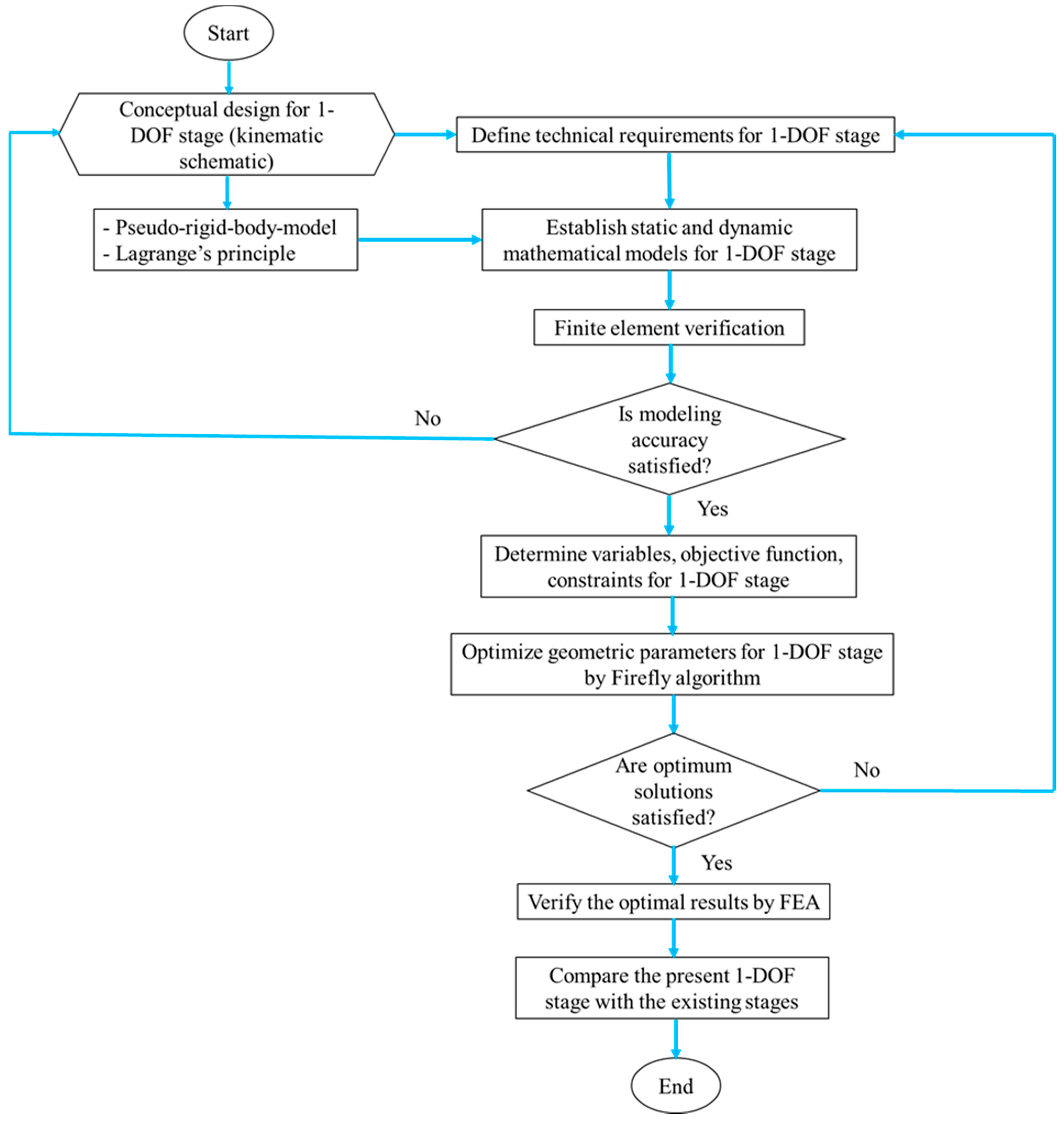
3. Proposed Method
- -
- A conceptual design of the 1-DOF stage is predetermined, i.e., built kinematic scheme.
- -
- Predetermine the technical specifications for the 1-DOF stage.
- -
- Establish the dynamic equation for the 1-DOF stage by developing the PRBM and Lagrange’s method.
- -
- Verify the theoretical results by using ANSYS software.
- -
- If the mathematical models are corrected, the process moves to next step. Otherwise, the process turns back the step 1.
- -
- Determine the design variables, objective function, and constraint function.
- -
- Firefly algorithm is utilized for the dynamic response of the proposed stage.
- -
- The optimal results are verified via simulations in ANSYS software.
- -
- The first frequency of the stage is compared with that from the previous studies.
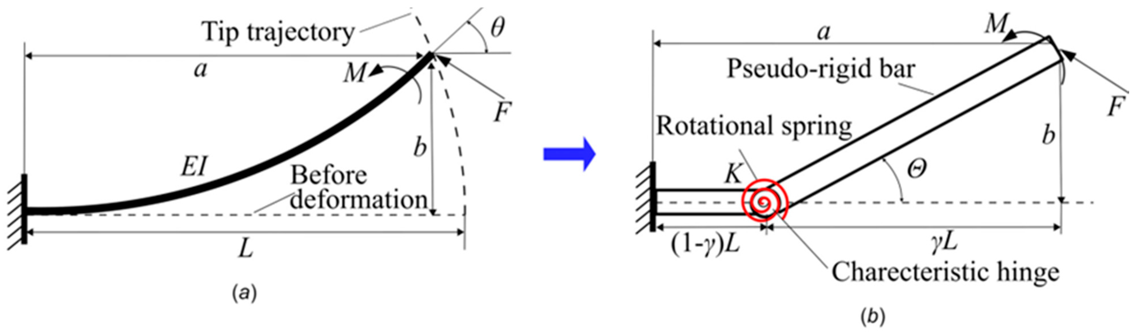
3.1. Overview of Pseudo-Rigid-Body Method
3.2. Lagrange’s Principle
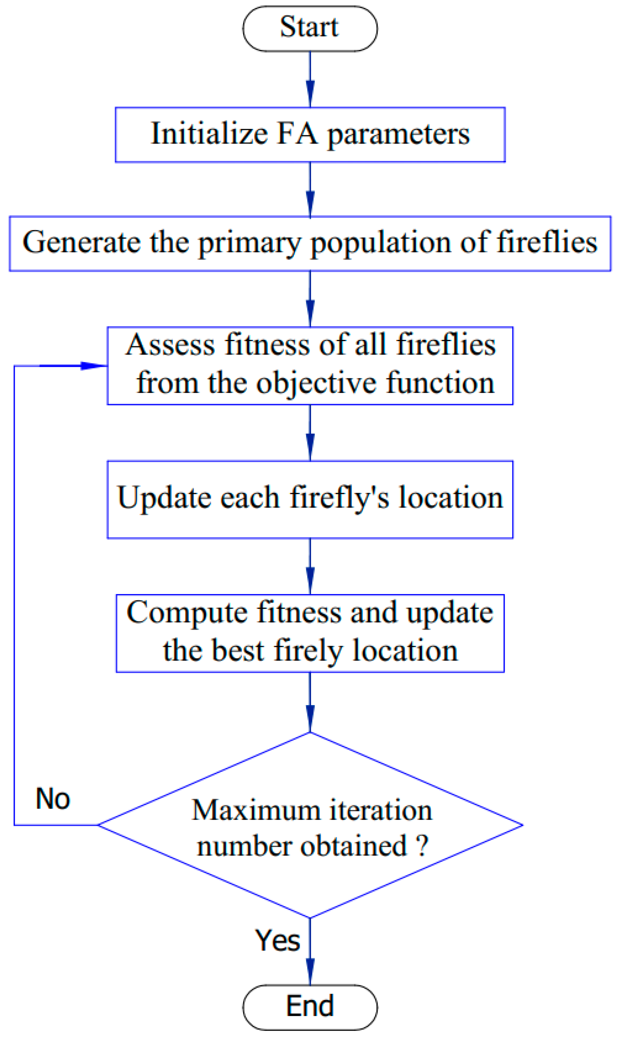
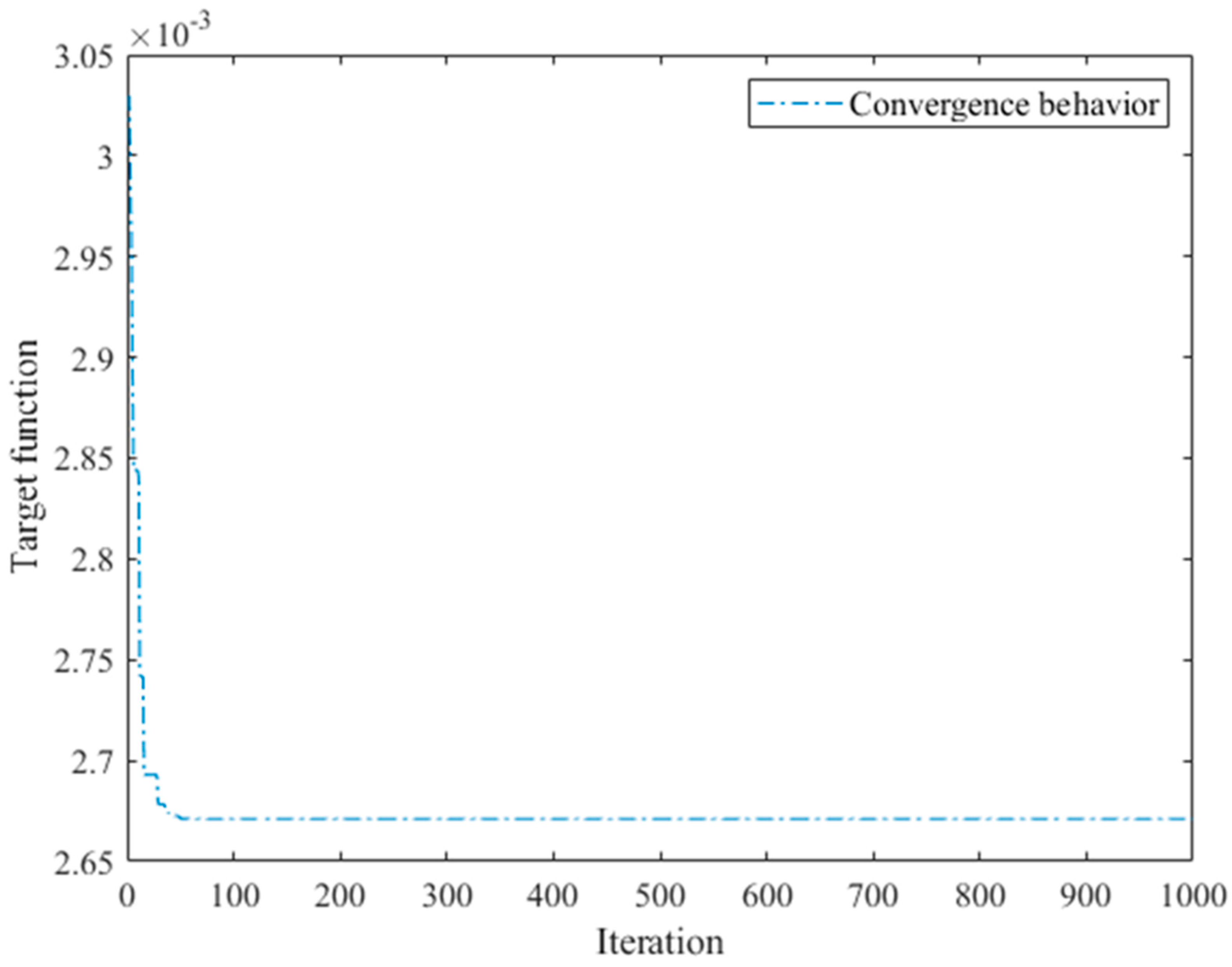
3.3. Firefly Algorithm
4. Results and Discussion
4.1. Dynamic Establishment for 1-DOF Stage
4.2. Verification of Established Analytical Models
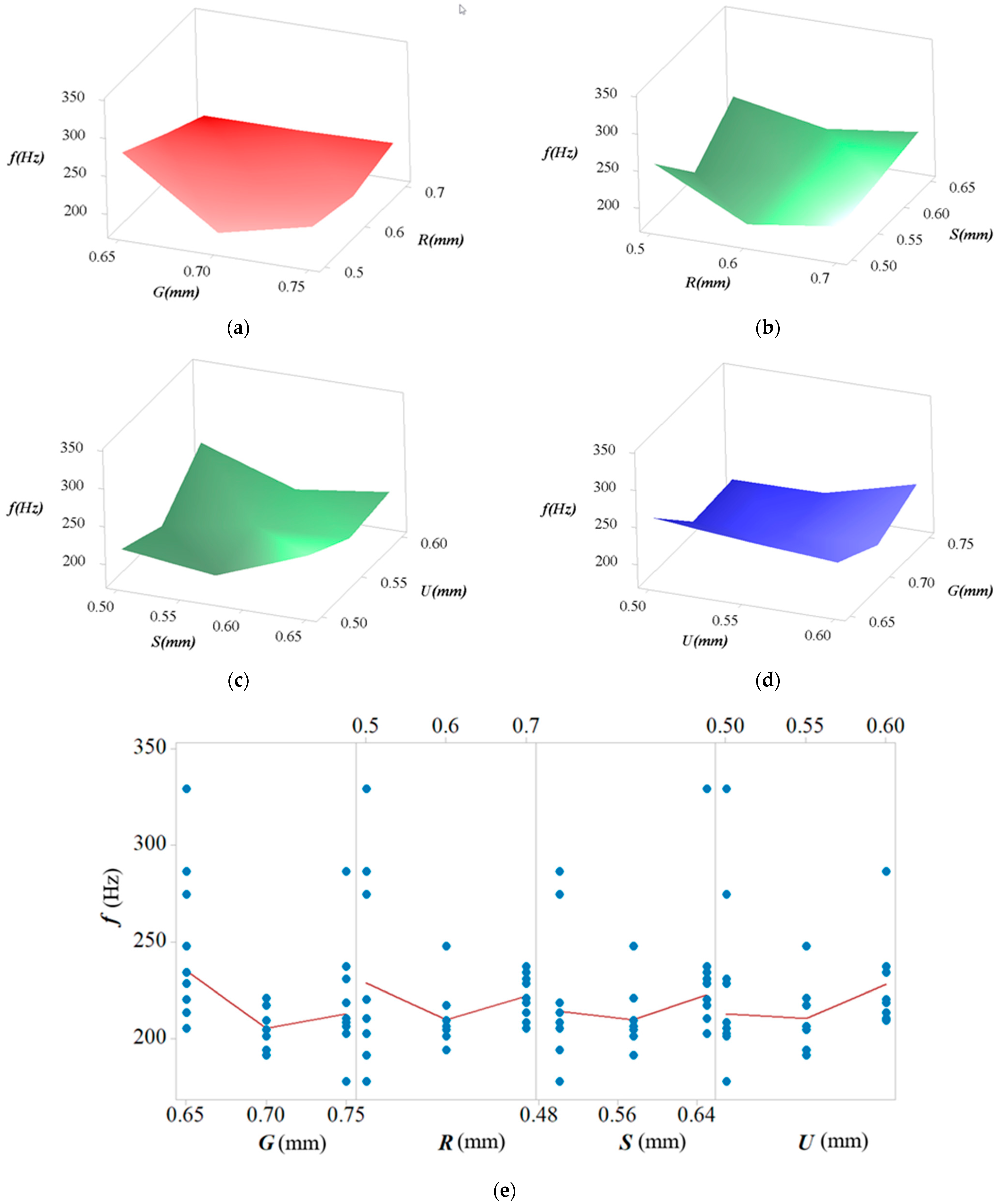
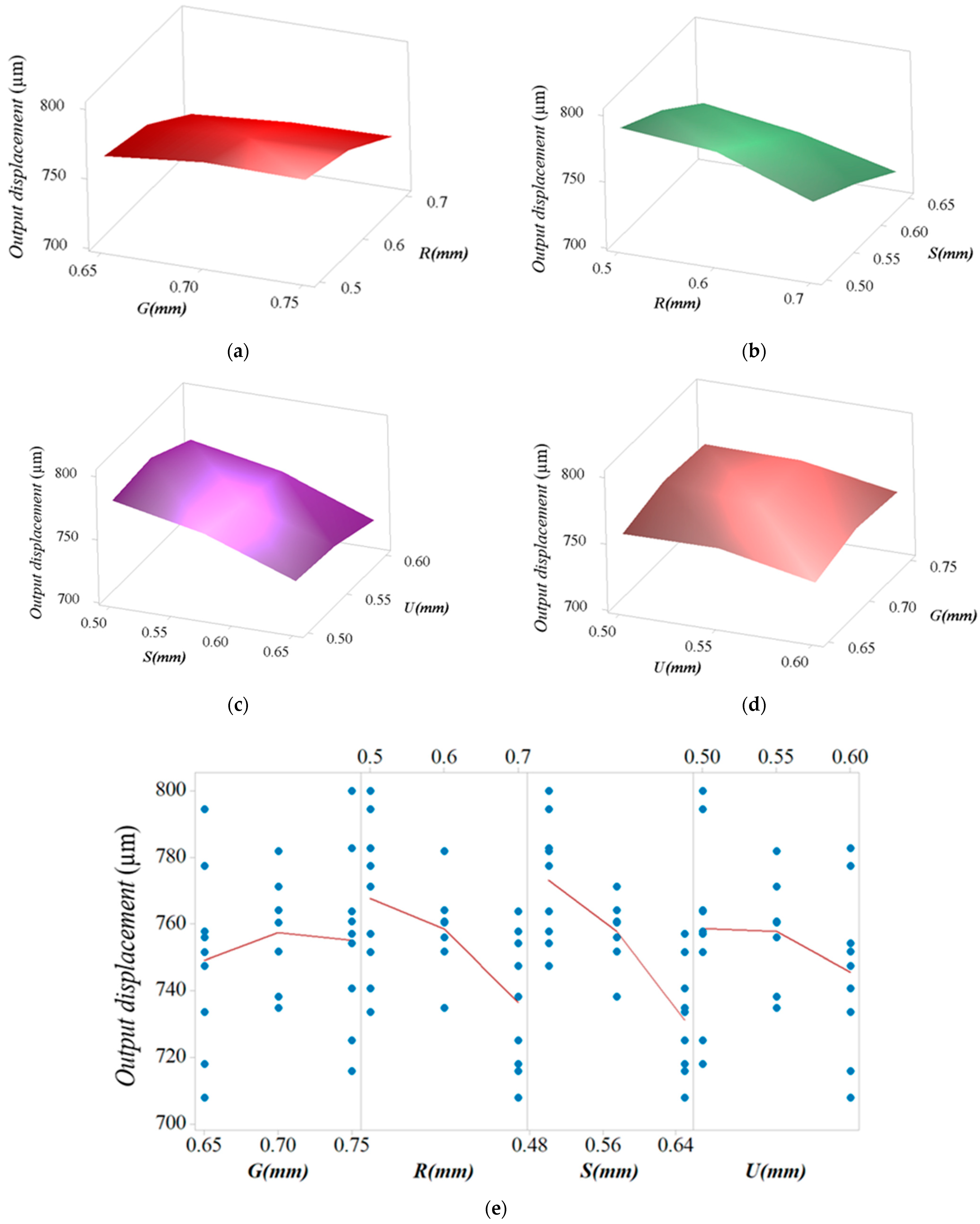
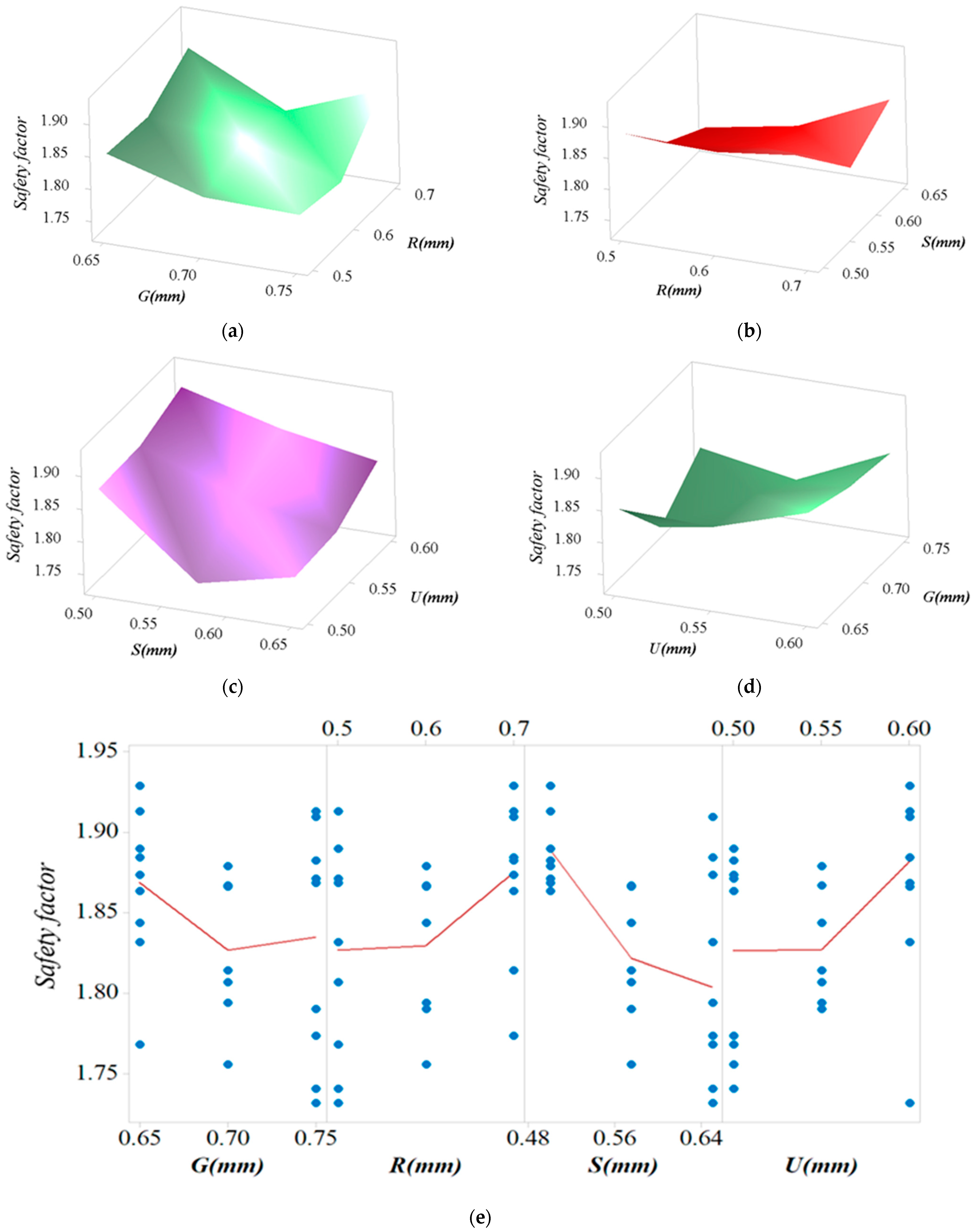
4.3. Parameter Optimization of 1-DOF Stage
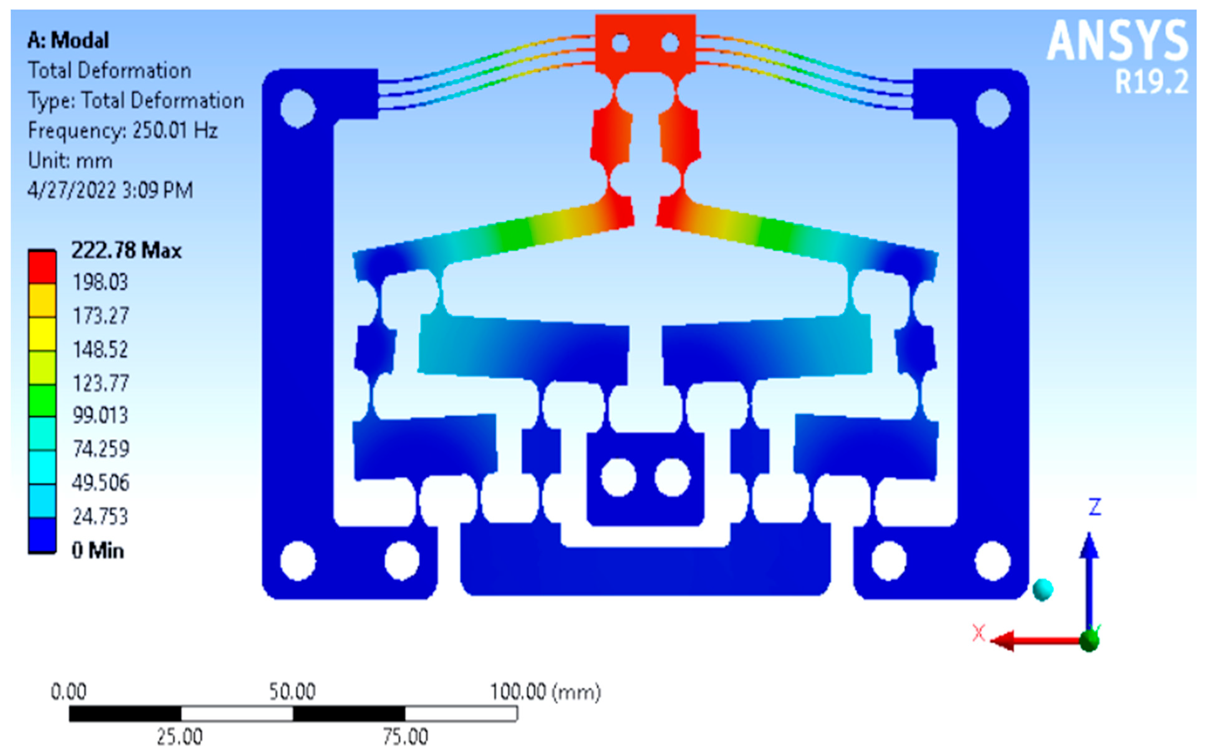
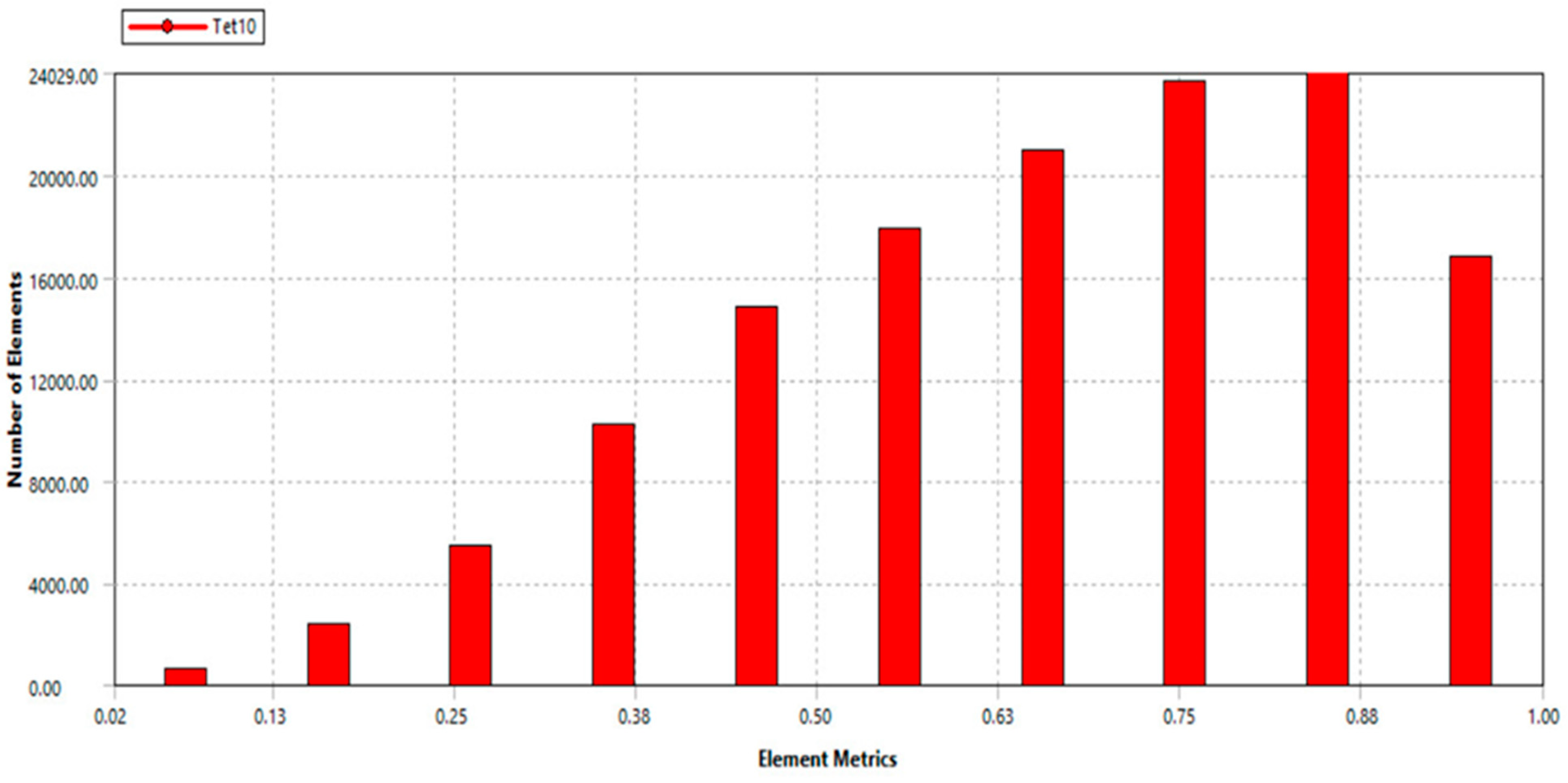
4.4. FEA Validation and Comparison
5. Conclusions
Author Contributions
Funding
Institutional Review Board Statement
Informed Consent Statement
Data Availability Statement
Conflicts of Interest
Nomenclature
| 1-DOF | One degree of freedom |
| SEM | Scanning electron microscope |
| TEM | Transmission electron microscope |
| PRBM | Pseudo-rigid-body model |
| ANFIS | Adaptive neuro-fuzzy inference system |
| PZT | Piezoelectric actuator |
| LAM 1 | Lever displacement amplifier of floor 1 |
| LAM 2 | Lever displacement amplifier of floor 2 |
| LAM 3 | Lever displacement amplifier of floor 3 |
| KC | Stiffness of the semi-circular flexural hinge |
| KE | Stiffness of elliptical hinge |
| KL | Stiffness of leaf hinge |
| FEA | Finite element analysis |
| DE | Differential evolutionary algorithm |
| NNA | Neural network algorithm |
| f | First natural frequency |
References
- Nowak, J.D.; Rzepiejewska-Malyska, K.A.; Major, R.C.; Warren, O.L.; Michler, J. In-situ nanoindentation in the SEM. Mater. Today 2010, 12, 44–45. [Google Scholar] [CrossRef]
- Ebenstein, D.M.; Pruitt, L.A. Nanoindentation of biological materials. Nano Today 2006, 1, 26–33. [Google Scholar] [CrossRef]
- Alderete, N.; Zaheri, A.; Espinosa, H. A Novel In Situ Experiment to Investigate Wear Mechanisms in Biomaterials. Exp. Mech. 2019, 59, 659–667. [Google Scholar] [CrossRef]
- Hu, Z.; Lynne, K.J.; Markondapatnaikuni, S.P.; Delfanian, F. Material elastic–plastic property characterization by nanoindentation testing coupled with computer modeling. Mater. Sci. Eng. A 2013, 587, 268–282. [Google Scholar] [CrossRef]
- O’Brien, W. Long-range motion with nanometer precision. Photonics Spectra 2005, 39, 80–81. [Google Scholar]
- Rabe, R.; Breguet, J.-M.; Schwaller, P.; Stauss, S.; Haug, F.-J.; Patscheider, J.; Michler, J. Observation of fracture and plastic deformation during indentation and scratching inside the scanning electron microscope. Thin Solid Films 2004, 470, 206–213. [Google Scholar] [CrossRef]
- Ding, B.; Li, Y.; Xiao, X.; Tang, Y.; Li, B. Design and analysis of a 3-DOF planar micromanipulation stage with large rotational displacement for micromanipulation system. Mech. Sci. 2017, 8, 117–126. [Google Scholar] [CrossRef] [Green Version]
- Jiang, C.; Lu, H.; Zhang, H.; Shen, Y.; Lu, Y. Recent Advances on In Situ SEM Mechanical and Electrical Characterization of Low-Dimensional Nanomaterials. Scanning 2017, 2017, 1985149. [Google Scholar] [CrossRef]
- Gianola, D.S.; Sedlmayr, A.; Mönig, R.; Volkert, C.A.; Major, R.C.; Cyrankowski, E.; Asif, S.A.S.; Warren, O.L.; Kraft, O. In situ nanomechanical testing in focused ion beam and scanning electron microscopes. Rev. Sci. Instrum. 2011, 82, 063901. [Google Scholar] [CrossRef] [Green Version]
- Haque, M.; Saif, M. Application of MEMS force sensors for in situ mechanical characterization of nano-scale thin films in SEM and TEM. Sens. Actuators A Phys. 2002, 97–98, 239–245. [Google Scholar] [CrossRef]
- Lu, Y.; Ganesan, Y.; Lou, J. A Multi-step Method for In Situ Mechanical Characterization of 1-D Nanostructures Using a Novel Micromechanical Device. Exp. Mech. 2009, 50, 47–54. [Google Scholar] [CrossRef]
- Xu, Q. Design and testing of a novel multi-stroke micropositioning system with variable resolutions. Rev. Sci. Instrum. 2014, 85, 025002. [Google Scholar] [CrossRef] [PubMed] [Green Version]
- Lu, K.; Zhang, J.; Chen, W.; Jiang, J.; Chen, W. A monolithic microgripper with high efficiency and high accuracy for optical fiber assembly. In Proceedings of the 9th IEEE Conference on Industrial Electronics and Applications, Hangzhou, China, 9–11 June 2014; pp. 1942–1947. [Google Scholar] [CrossRef]
- Putra, A.S.; Huang, S.; Tan, K.K.; Panda, S.K.; Lee, T.H. Design, modeling, and control of piezoelectric actuators for intracytoplasmic sperm injection. IEEE Trans. Control Syst. Technol. 2007, 15, 879–890. [Google Scholar] [CrossRef]
- Huang, H.; Zhao, H.; Mi, J.; Yang, J.; Wan, S.; Xu, L.; Ma, Z. A novel and compact nanoindentation device for in situ nanoindentation tests inside the scanning electron microscope. AIP Adv. 2012, 2, 012104. [Google Scholar] [CrossRef] [Green Version]
- Huang, H.; Zhao, H.; Mi, J.; Yang, J.; Wan, S.; Yang, Z.; Yan, J.; Ma, Z.; Geng, C. Experimental research on a modular miniaturization nanoindentation device. Rev. Sci. Instrum. 2011, 82, 095101. [Google Scholar] [CrossRef] [PubMed]
- Zhao, H.; Huang, H.; Fan, Z.; Yang, Z.; Ma, Z. Design, Analysis and Experiments of a Novel in situ SEM Indentation Device. In Nanoindentation in Materials Science; IntechOpen: London, UK, 2012. [Google Scholar] [CrossRef] [Green Version]
- Dang, M.P.; Le, H.G.; Le Chau, N.; Dao, T.-P. A multi-objective optimization design for a new linear compliant mechanism. Optim. Eng. 2019, 21, 673–705. [Google Scholar] [CrossRef]
- Wang, P.; Xu, Q. Design of a flexure-based constant-force XY precision positioning stage. Mech. Mach. Theory 2017, 108, 1–13. [Google Scholar] [CrossRef]
- Fan, S.; Liu, H.; Fan, D. Design and development of a novel monolithic compliant XY stage with centimeter travel range and high payload capacity. Mech. Sci. 2018, 9, 161–176. [Google Scholar] [CrossRef] [Green Version]
- Wadikhaye, S.; Yong, Y.; Moheimani, S. Design of a compact serial-kinematic scanner for high-speed atomic force microscopy: An analytical approach. Micro Nano Lett. 2012, 7, 309–313. [Google Scholar] [CrossRef] [Green Version]
- Gauthier, M.; Piat, E. Control of a particular micro-macro positioning system applied to cell micromanipulation. IEEE Trans. Autom. Sci. Eng. 2006, 3, 264–271. [Google Scholar] [CrossRef] [Green Version]
- Ding, B.; Yang, Z.-X.; Zhang, G.; Xiao, X. Optimum design and analysis of flexure-based mechanism for non-circular diamond turning operation. Adv. Mech. Eng. 2017, 9, 1687814017743353. [Google Scholar] [CrossRef] [Green Version]
- Ding, B.; Yang, Z.-X.; Xiao, X.; Zhang, G.; Yangd, Z.-X. Design of Reconfigurable Planar Micro-Positioning Stages Based on Function Modules. IEEE Access 2019, 7, 15102–15112. [Google Scholar] [CrossRef]
- Ding, B.; Zhao, J.; Li, Y. Design of a spatial constant-force end-effector for polishing/deburring operations. Int. J. Adv. Manuf. Technol. 2021, 116, 3507–3515. [Google Scholar] [CrossRef]
- Deng, L.; Ling, M. Design and integrated stroke sensing of a high-response piezoelectric direct-drive valve enhanced by push–pull compliant mechanisms. Rev. Sci. Instrum. 2022, 93, 035008. [Google Scholar] [CrossRef] [PubMed]
- Kim, H.-Y.; Ahn, D.-H.; Gweon, D.-G. Development of a novel 3-degrees of freedom flexure based positioning system. Rev. Sci. Instrum. 2012, 83, 055114. [Google Scholar] [CrossRef]
- Wang, F.; Liang, C.; Tian, Y.; Zhao, X.; Zhang, D. Design and Control of a Compliant Microgripper With a Large Amplification Ratio for High-Speed Micro Manipulation. IEEE/ASME Trans. Mechatron. 2016, 21, 1262–1271. [Google Scholar] [CrossRef]
- Chang, S.H.; Du, B.C. A precision piezodriven micropositioner mechanism with large travel range. Rev. Sci. Instrum. 1998, 69, 1785–1791. [Google Scholar] [CrossRef]
- Ling, M.; Howell, L.L.; Cao, J.; Chen, G. Kinetostatic and Dynamic Modeling of Flexure-Based Compliant Mechanisms: A Survey. Appl. Mech. Rev. 2020, 72, 030802. [Google Scholar] [CrossRef] [Green Version]
- Le Chau, N.; Tran, N.T.; Dao, T.-P. Topology and size optimization for a flexure hinge using an integration of SIMP, deep artificial neural network, and water cycle algorithm. Appl. Soft Comput. 2021, 113, 108031. [Google Scholar] [CrossRef]
- Dang, M.P.; Le, H.G.; Le, N.N.T.; Le Chau, N.; Dao, T.-P. Multiresponse Optimization for a Novel Compliant Z-Stage by a Hybridization of Response Surface Method and Whale Optimization Algorithm. Math. Probl. Eng. 2021, 2021, 9974230. [Google Scholar] [CrossRef]
- Dang, M.P.; Le, H.G.; Le Chau, N.; Dao, T.-P. Optimization for a Flexure Hinge Using an Effective Hybrid Approach of Fuzzy Logic and Moth-Flame Optimization Algorithm. Math. Probl. Eng. 2021, 2021, 6622655. [Google Scholar] [CrossRef]
- Yang, X.S.; He, X. Firefly algorithm: Recent advances and applications. Int. J. Swarm Intell. 2013, 1, 36–50. [Google Scholar] [CrossRef] [Green Version]
- Yildiz, A.R. Hybrid Taguchi-differential evolution algorithm for optimization of multi-pass turning operations. Appl. Soft Comput. 2013, 13, 1433–1439. [Google Scholar] [CrossRef]
- Dinh, V.B.; Le Chau, N.; Le, N.T.P.; Dao, T.-P. Topology-based geometry optimization for a new compliant mechanism using improved adaptive neuro-fuzzy inference system and neural network algorithm. Eng. Comput. 2021, 1–30. [Google Scholar] [CrossRef]
- Xu, Q. Design, testing and precision control of a novel long-stroke flexure micropositioning system. Mech. Mach. Theory 2013, 70, 209–224. [Google Scholar] [CrossRef]
- Li, X.; Tian, Y. The design and new controller of a 1-DOF precision positioning platform. In Proceedings of the 2013 International Conference on Manipulation, Manufacturing and Measurement on the Nanoscale, Suzhou, China, 26–30 August 2013; pp. 190–194. [Google Scholar] [CrossRef]
- Le Chau, N.; Tran, N.T.; Dao, T.-P. An Optimal Design Method for Compliant Mechanisms. Math. Probl. Eng. 2021, 2021, 5599624. [Google Scholar] [CrossRef]


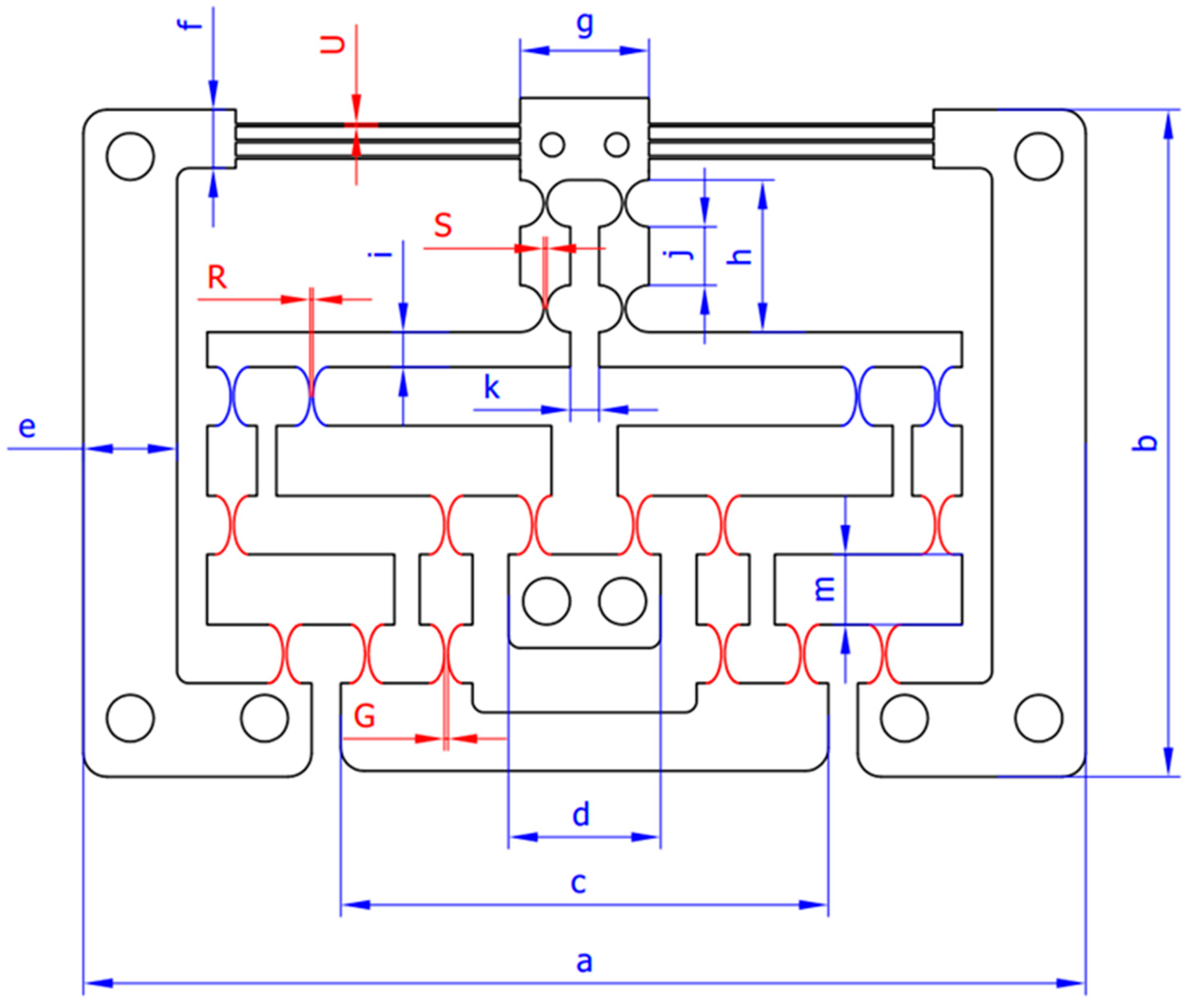
| Symbol | Value | Symbol | Value | Unit |
|---|---|---|---|---|
| a | 171 | i | 6 | mm |
| b | 108 | j | 10 | mm |
| c | 82 | k | 5 | mm |
| d | 26 | m | 12 | mm |
| e | 16 | G | 0.65 ≤ G ≤ 0.75 | mm |
| f | 10 | R | 0.5 ≤ R ≤ 0.7 | mm |
| g | 22 | S | 0.5 ≤ S ≤ 0.65 | mm |
| h | 26 | U | 0.5 ≤ U ≤ 0.6 |
| Response | Theory | FEA | Error (%) |
|---|---|---|---|
| f (Hz) | 176.96 | 195.07 | 9.28 |
| Response | Optimal Result | Initial Design Result | Improvement (%) |
|---|---|---|---|
| f (Hz) | 226.8458 | 176.96 | 28.19 |
| Response | Optimal Design | Simulation | Error (%) |
|---|---|---|---|
| f (Hz) | 226.8458 | 250.01 | 9.27 |
| Response | Presented Method | DE | NNA |
|---|---|---|---|
| f (Hz) | 226.8458 | 226.8456 | 226.8448 |
Publisher’s Note: MDPI stays neutral with regard to jurisdictional claims in published maps and institutional affiliations. |
© 2022 by the authors. Licensee MDPI, Basel, Switzerland. This article is an open access article distributed under the terms and conditions of the Creative Commons Attribution (CC BY) license (https://creativecommons.org/licenses/by/4.0/).
Share and Cite
Dang, M.P.; Le, H.G.; Tran, N.T.D.; Chau, N.L.; Dao, T.-P. Optimal Design and Analysis for a New 1-DOF Compliant Stage Based on Additive Manufacturing Method for Testing Medical Specimens. Symmetry 2022, 14, 1234. https://doi.org/10.3390/sym14061234
Dang MP, Le HG, Tran NTD, Chau NL, Dao T-P. Optimal Design and Analysis for a New 1-DOF Compliant Stage Based on Additive Manufacturing Method for Testing Medical Specimens. Symmetry. 2022; 14(6):1234. https://doi.org/10.3390/sym14061234
Chicago/Turabian StyleDang, Minh Phung, Hieu Giang Le, Nguyen Thanh Duy Tran, Ngoc Le Chau, and Thanh-Phong Dao. 2022. "Optimal Design and Analysis for a New 1-DOF Compliant Stage Based on Additive Manufacturing Method for Testing Medical Specimens" Symmetry 14, no. 6: 1234. https://doi.org/10.3390/sym14061234
APA StyleDang, M. P., Le, H. G., Tran, N. T. D., Chau, N. L., & Dao, T.-P. (2022). Optimal Design and Analysis for a New 1-DOF Compliant Stage Based on Additive Manufacturing Method for Testing Medical Specimens. Symmetry, 14(6), 1234. https://doi.org/10.3390/sym14061234