Article

A Novel Integrated Method for Harmonic Suppression and Reactive Power Compensation in Distribution Network

1
School of Information Science and Engineering, Wuhan University of Science and Technology, Wuhan 430081, China
2
School of Electrical and Mechanical Engineering, Pingdingshan University, Pingdingshan 467036, China
3
School of Automation, Wuhan University of Technology, Wuhan 430070, China
*
Author to whom correspondence should be addressed.
Symmetry 2022, 14(7), 1347; https://doi.org/10.3390/sym14071347
Submission received: 2 June 2022 / Revised: 19 June 2022 / Accepted: 23 June 2022 / Published: 29 June 2022
(This article belongs to the Special Issue Symmetry and Asymmetry in Securing Data Sharing)

Abstract

:
Aiming at the serious harmonic pollution and the low power factor in the distribution network of industrial enterprises, this paper develops an integrated method for harmonic suppression and reactive power compensation suitable for the distribution network of industrial enterprises. The integrated method realizes the dual functions of harmonic filtering and reactive power compensation, and filters out the harmonic current to get a symmetrical current waveform while ensuring safe operation of the power compensator. In addition, it solves the problems of high harmonic content, small power factor in the distribution network, and device burnout caused by direct input of reactive power compensator. The main contributions of this paper are as follows: (1) According to the demand for the integration of harmonic suppression and reactive power compensation, the steps of integrated method for harmonic suppression and reactive power compensationare proposed, and then the methods for harmonic filtering and reactive power compensation are investigated; (2) a method for designing the capacity of a filter capacitor and the rated parameter of an electromagnetic coupling reactance converter is proposed, and an optimization simulation system is constructed to design the parameters of the filter; (3) a simulation system is developed, followed by parameter design and simulation analysis of harmonic filtering subsystem (HFSS), reactive power compensation subsystem (RPCSS) and the integrated system of harmonic suppression and reactive power compensation. Simulation results verify that the HFSS is put into operation first and then switched off later to ensure the normal operation of other equipment in the distribution network. After the treatment, the power factor, harmonic current content and total distortion rate all meet the national standards. The integrated method can dynamically track harmonics and reactive power changes, filter out harmonics, improve power factor and the symmetry level of the power source, and ensure the normal operation of other equipment in the distribution network. The research results lay a certain theoretical and technical foundation for the harmonic filtering and reactive power compensation theory, technology and its device innovation to achieve effective suppression of power harmonics and reactive power compensation.

1. Introduction

Nowadays, electricity is widely applied in industrial manufacturing. The symmetry level of voltage and current waveform is one of the main indicators for measuring power quality. With the advances in technology, the power demand of Chinese enterprises is increasing dramatically, and a large number of new impact loads and non-linear loads and non-symmetrical loads have emerged, resulting in harmonic amplification and power factor reduction in the distribution network. The power factor affects the deviation of supply voltage to obtain a non-symmetrical voltage waveform, and the harmonics lead to the distortion of current waveform to get a non-symmetrical current waveform. Therefore, they are important factors affecting power quality. Due to the serious harmonic pollution in the distribution network of industrial enterprises, the existing reactive power compensators are unable to operate safely. This, in turn, results in low power factor, poor power quality, and large power consumption. Thus, energy saving of enterprises cannot be ignored [1,2,3,4,5]. The power quality indices are governed by various standard regulations, such as IEEE-519-2014 [6]. The author used the French CA8335 power quality analyzer to measure the power factor and harmonic current of the power plant from 8:00 to 18:00. It was found that when the measured power quality was the worst, the power factor was 0.51, the 5th harmonic ratio was 18 %, the 7th harmonic ratio was 9%, the 11th harmonic ratio was 10%, the 13th harmonic ratio was 6%, and the total harmonic distortion rate was 23.8%. The reason is that when the harmonics are large, the existing reactive power compensator of enterprises cannot be operated normally, and power devices such as compensation capacitors will be burned in severe cases, and the power factor is much lower than the national standard of 0.9–1.
The author developed a “static var compensator based on electromagnetic coupled reactor” to realize dynamic reactive power compensation, and a “dynamically tuned harmonic filter (DTHF)” to filter the harmonics in the power grid while providing part of the reactive power at the same time [7,8,9,10,11]. However, a single filter or reactive power compensator cannot solve the harmonic pollution and the low power factor problems existing in the enterprise distribution network. To this end, this paper proposes an integrated method for harmonic suppression and reactive power compensation suitable for the distribution network of industrial enterprises.
The power filters have been used to mitigate the power harmonics, such as passive power filter (PPF), active power filter (APF) and series hybrid active power filter (SHAPF). The PPF tunes the harmonics of the specified order through the LC filter circuit, and effectively eliminate the harmonics of this order by taking advantage of its characteristic of minimum impedance at resonance. Thus, the harmonic current of this order cannot flow into the power grid, thereby achieving the purposes of harmonics suppression and limiting the harmonic current below the standard value to get a symmetrical current waveform. Characterized by simple structure, relatively low cost, and convenient maintenance, PPFs are the major method widely applied for harmonic filtering at present. Nevertheless, the capacitance and inductance of traditional PPF are fixed, and cannot be adjusted freely according to harmonic changes, impairing the filtering effect. When the harmonic current increases, it will overload the filter and damage the electrical components. After traditional PPFs work for a long time, their inductance and capacitance will deviate from the standard value as the temperature changes, increasing the total harmonic distortion. In severe cases, the resonance point drifts and resonates with the system, impairing filter efficiency and filter performance [12,13,14,15,16,17,18,19].
Aiming at the shortcomings of traditional PPF, the author proposed a dynamic tuning passive filter(DTPF) based on the traditional LC filtering principle. This method can dynamically adjust the capacitor inductance and filter the harmonics in the circuit, avoid the resonance point deviation resulted from the aging of the medium, for example, and ensure the safe and stable operation of equipment [20]. The APF filter has been investigated and many active power filter topologies have been researched. There are three kinds of typical APF according to their configurations: (1) parallel APF; (2) hybrid active power filter(HAPF); and (3) unified power quality conditioner. Among all these APF, the series hybrid active power filter (SHAPF) has attracted much attention of electrical engineers and researchers, as it can take advantage of the passive power filter and reduce the rating of active power filters, as well as greatly increasing the system harmonic impedance instead of the fundamental impedance [21,22,23].
With the development of science and technology, the load structure in the distribution network has undergone great changes, with the inductive load increasing. Moreover, the reactive power supplied by generators is far from meeting the reactive power demand of electrical loads. In order to ensure the normal operation of various kinds of power equipment and to improve equipment utilization, it is necessary to compensate reactive power. Parallel capacitors can compensate fixed reactive power, and have a wide range of applications for their flexible compensation methods, low costs, simple maintenance, and small power loss. However, their capacity is fixed and not adjustable, and it is easy to have parallel resonance with the inductor in the system, resulting in amplification of harmonic currents. The amplified harmonic currents are transmitted to the distribution network through the power transformer, increasing the adverse impact of harmonics on the system. In serious cases, they will cause system oscillations, which in turn lead to failure of the equipment in the distribution network and breakdown of the power supply system [24,25]. Therefore, filter devices should be installed in places with high harmonic interference and reactive power compensation.
At present, the commonly used reactive power compensation mainly adopts Static Var Compensator (SVC). SVC mainly controls the capacity of reactors and capacitors connected to the system through the saturation of a controllable saturable reactor or the conduction of thyristor, so as to change the admittance of the power transmission system. Its typical representative is the reactive power compensator using a thyristor as the control device. The TCR + SVC device is the most widely applied SVC at present, and has become the mainstream of high-voltage SVC technology due to its fast response and phase compensation capability [26,27].
It is known from the above analyses that the distribution network of industrial enterprises is facing serious harmonic pollution, which results in the fact that the existing reactive power compensators are unable to be used safely, with low power factor, a non-symmetrical current waveform, and poor power quality. However, these problems are difficult to solve by using reactive power compensators or harmonic filters alone. In recent years, many experts have put forward solutions for the optimization of power quality. The main problems that need to be addressed are as follows. The first is that the harmonic content of the distribution network is large, so the reactive power compensator may be burned out if it is directly applied; the second is the coordination between harmonic filtering and reactive power compensation; the third is the mechanism of harmonic suppression dynamic tuning and dynamic reactive power compensation.
This paper focuses on the serious harmonic pollution and the low power factor in the distribution network of industrial enterprises. A novel integrated method for harmonic suppression and reactive power compensation has been devised. The integrated method realized the dual functions of harmonic filtering and reactive power compensation and filtered out harmonics while ensuring safe operation of the power compensator. The integrated method could dynamically track harmonics and reactive power changes, filter out harmonics, and improve the power factor and the symmetry level of the power source. The research results lay a certain theoretical and technical foundation for the harmonic filtering and reactive power compensation theory, technology and its device innovation to achieve effective suppression of power harmonics and reactive power compensation.
The performance of the integrated method for harmonic suppression and reactive power compensation in the distribution network is evaluated based on the following objectives.
  • To restrict harmonic mitigation as per the IEEE 519-2014 standard in such a way that source currents are sinusoidal, irrespective of harmonic content in distorted source voltage and non-linear load.
  • To eradicate the effect of poor load power factor, such that it results in an almost united power factor on the supply side.
  • To decrease apparent power supplied from the source for given source voltage conditions.
The rest of the paper is organized under the following headings. Section 2 begins with a discussion on the integration mechanism, with steps of integrated method and topological structure of the integrated system, followed by a detailed description of harmonic current filtering method of HFSS. This includes the dynamic tuning condition for HFSS, parameters design, inductance regulation, and a two-step optimization algorithm in Section 3; Section 4 presents a reactive power compensation method of RPCSS; Section 5 illustrates integration simulation and discussion. Finally, the reported work is concluded with important remarks in Section 6.

2. Integration Mechanism of Harmonic Suppression and Reactive Power Compensation

The integration of harmonic suppression and reactive power compensation in the distribution network is realized through an integrated system composed of a harmonic suppression subsystem (HFSS), a reactive power compensation subsystem (RPCSS), a digital power signal detection unit (DPSCU), controller, etc. Among them, dynamic tuned harmonic filtering is realized by the HFSS and dynamic reactive power compensation by the RPCSS. The HFSS is put into operation first and then switched off later to ensure the normal operation of other equipment in the distribution network.

2.1. Steps of Integrated Method for Harmonic Suppression and Reactive Power Compensation

The power switch is turned on to connect the integrated system to the distribution network. Let the start flag F s be “0”, the stop flag F p be “0”, the start button be S A , and the stop button be S B , then the integration of harmonic suppression and reactive power compensation can be realized through the following steps:
  • S 1 : Call the start and stop interrupt service.
The interrupt is adopted for control:
An application for start interruption is submitted if the start button S A is effective. The controller performs control by judging the start flag F s and the stop flag F p . When the start flag F s and the stop flag F p are both “0”, the controller sets the start flag F s to “1”, and calls “Run Interrupt Service Routine” ( S 2 );
An application for stop interruption is submitted if the stop button S B is effective. When the start flag F s is “1”, the controller sets the stop flag F p to “1” and the start flag F s to “0”, and calls “Stop Interrupt Service Routine” ( S 3 ).
  • S 2 :Run interrupt service routine.
S 21 : Initialization
The minimum harmonic current that satisfies the harmonic index is I b , and the power factor index is p h 0 ; the updated flag F u is “1”, harmonic suppression flag F r h is “0”, the reactive power compensation flag F r h is “0”; then entering S 22 ;
S 22 : Power signal detection
When the updated flag F u is “1”, the signals in the distribution network are collected, including current, voltage, active power P, reactive power Q, power factor p h , and the h-order harmonic current I h that needs to be filtered. After the data are collected and stored, the controller sets the updated flag F u to “1”, harmonic suppression flag F r h to “1”, and then the updated flag F u to “0”; then moves on to S 23 .
S 23 : Dynamically tuned filtering
When the harmonic suppression flag F r h is “1” and the reactive power compensation flag F r q is “0”, the controller switches on HFSS. The working status of HFSS is determined by any of the following conditions:
When I h is larger than I b , HFSS enters the dynamic tuning state, adjusts the resonance frequency, filters out the harmonics, and ensures the stable operation of the power grid until the harmonic current meets the harmonic standards to get a symmetrical current waveform. In addition, it provides a certain amount of reactive power and sets the harmonic suppression flag F r h to “0”; When I h is less than or equal to I b ; that is, the harmonic current meets the harmonic standard, HFSS maintains the working state at the previous moment; After that, the reactive power compensation flag F r q is set to “1”; then moves on to S 24 .
S 24 : Dynamic reactive power compensation
When the reactive power compensation flag F r q is “1”, the controller switches on the RPCSS, and the working status of RPCSS is determined by any of the following conditions: When p h is smaller than p h 0 , RPCSS enters the dynamic reactive power compensation state. According to P, Q, p h and p h 0 , the reactive power capacity Q b , RPCSS sends reactive power to the distribution network until the power factor meets the requirements; that is, p h exceeds p h 0 . After that, it sets the reactive power compensation flag F r q to “0”;
When p h is larger than p h 0 , or when the power factor meets the reactive power compensation standard, RPCSS will maintain the working state at the previous moment;
After that, the flag F u is updated to “1”; then moves on to S 22 .
  • S 3 :Stop interrupt service routine.
First, the reactive power compensation subsystem is switched off, and then the HFSS to ensure that the main power components of the RPCSS are not burned out due to harmonics. Then, the incoming power switch is turned off.
Through the above steps, the harmonics and reactive power changes are dynamically tracked, the harmonics are filtered out, and the power factor is improved, thus leading to a more symmetrical waveform and successfully avoiding power grid problems.

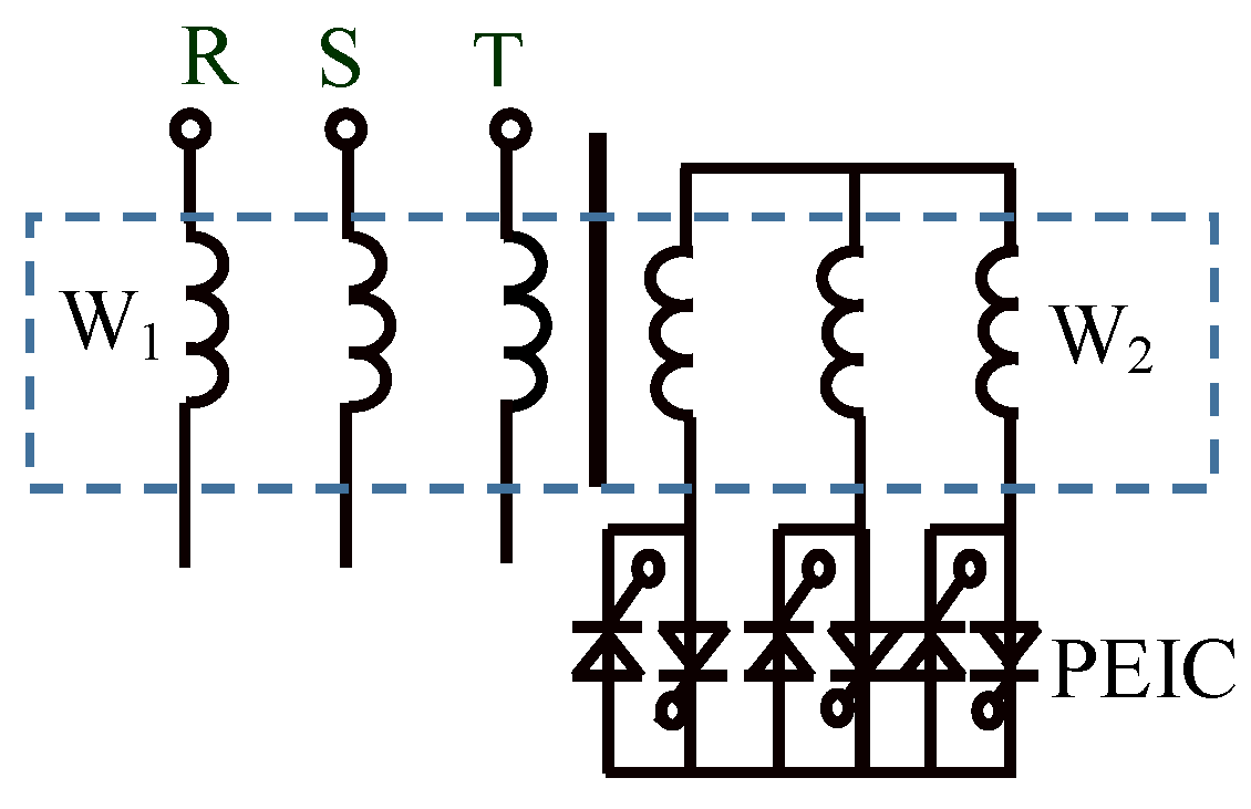
2.2. Topological Structure of the Integrated System

To achieve the integration of harmonic suppression and reactive power compensation, the topological structure of the integrated system is constructed, as shown in Figure 1.
In Figure 1, Q F is a circuit breaker (the incoming power switch), which is responsible for switching the power supply on or off.
The HFSS is composed of a contactor KM 1 , an electromagnetic coupling reactor SS (the equivalent inductance of the primary reactance winding is L 11 ), fast-acting fuses FU 11 –FU 1 m , contactors KM 11 –KM 1 m , and a filter capacitor bank C 11 –C 1 m (the equivalent capacitance is C 1 ). The controller switches on and off the filter capacitor bank C 11 –C 1 m by controlling on/off of contactors KM 11 –KM 1 m , and obtains the equivalent capacitance C 1 required for reactive power compensation. L 11 and C 1 form a low-impedance circuit, so that the harmonic current in the power distribution system directly flows into the HFSS to filter out harmonics.
The RPCSS is composed of the contactor KM 2 , fast-acting fuses FU 21 –FU 2 n + 1 , contactors KM 21 –KM 2 n + 1 and reactive compensation capacitor bank C 2 (consists of C 11 –C 1 n ). The RPCSS calculates the reactive power required to be compensated based on the detected reactive power shortage. By controlling the on/off of the contactors KM 21 –KM 2 n , the controller switches on the corresponding capacitors C 21 –C 2 n to generate reactive power so as to compensate the system.
The DPSCU, by analyzing the voltage and current signals collected by the voltage and current measurement sensor PAV, obtains such signals as the current, voltage, active power P, reactive power Q, power factor p h , and h-order harmonic current I h that need to be filtered out in the distribution network, and transmits them to the controller via RS485 bus.
The coordination between HFSS and RPCSS is realized by the controller.

3. Harmonic Current Filtering Method of HFSS

As shown in Figure 1, when KM 1 is connected and KM 2 is disconnected, the HFSS is put into operation. Aiming at the problem that the parameters for the passive filter cannot be adjusted continuously and the dynamic tuning cannot be realized, the harmonic current filtering method is proposed. The specific steps of the method are as follows:
  • Propose the constraint conditions that must be met during dynamic tuning so as to improve the stability of HFSS while filtering out the h-order harmonic current;
  • Adopt the minimum capacitance method to design the parameters of the electromagnetic coupling reactor (SS) and filter capacitors of the HFSS according to the h-order harmonic current I h that needs to be filtered out;
  • Propose the method for adjusting the inductance of the SS; that is, the power electronic impedance converter (PEIC) adjusts the equivalent inductance of SS to L 11 by adjusting its thyristor trigger angle according to the desired control signal U z ;
  • Uses the two-step optimization algorithm to get the control signal U z needed to make h-order harmonic current I f flowing into the HFSS to reach the maximum;
  • Switch on and off the filter capacitor bank C 11 –C 1 m by controlling the on/off of the contactors KM 11 –KM 1 m , so as to obtain the equivalent capacitance C 1 required for reactive power compensation. Thus, L 11 and C 1 form a low impedance loop so that the harmonic current in the power distribution system flows directly into the filter subsystem to filter out harmonics.

3.1. Dynamic Tuning Condition for HFSS

There is no background harmonic current in the power grid or distribution system to be treated. The harmonic currents in the system are all generated by the non-linear load, and its magnitude is I h . In order to filter the h-order harmonic current in the distribution system, h-order HFSS is installed. Figure 2 shows the flow of the h-order harmonic current.
In Figure 2, T 1 and T 2 are the installation positions of the DPSCU. After passing through the HFSS, the harmonic current injected by the harmonic source load into the system is
I s = I h I f ,
According to the impedance frequency characteristics of HFSS, when it is tuned to the resonance frequency f h , the h-order harmonic current I f absorbed by the HFSS reaches its maximum, and h-order harmonic current I s injected into the power grid reaches the minimum. Therefore, the control objective is to maximize I f and the following two constraint conditions must be satisfied during dynamic tuning:
  • Condition 1: The h-order harmonic current I h generated by the the nonlinear load must be less than or equal to the maximum h-order harmonic current I f ( h ) that the HFSS can filter.
  • Condition 2: Let I r e f ( h ) be the allowable h-order harmonic current into the public grid prescribed in the Harmonics standards (IEEE Std 519—2014), and the HFSS is tuned when the h-order harmonic current I s ( h ) in the grid is larger than I r e f ( h ) ; otherwise, the HFSS continues to output the control signal U z (k−1) from the previous moment.
Condition 1 is to restrict the magnitude of the h-order harmonic current generated by the non-linear loads, also known as non-symmetrical loads; that is, the premise of harmonic filtering is that the h-order harmonic current generated by the non-linear loads cannot exceed the capacity of HFSS. Condition 2 is to constrain the tuning conditions to avoid the constant tuning of HFSS. That is, the HFSS starts tuning only when the h-order harmonic current in the power grid exceeds the allowable value specified in the national standard. In this way, the h-order harmonic current is dynamic filtered while improving the stability of HFSS.

3.2. Parameter Design of Filter Capacitors

The parameters for the filter capacitors of HFSS and electromagnetic coupling reactor SS are designed based on the minimum capacitance method.
In the HFSS, the investment of capacitors is generally large. In order to reduce the cost of filters, it is necessary to minimize the capacity of capacitors while meeting filtering requirements. Therefore, with the minimum capacitance of the filter capacitor determined by the minimum capacitance method, this paper calculates the optimal capacity of the filter capacitor so as to determine the capacitance of the filter capacitor. The specific method is as follows:
When the HFSS resonates, the inductive reactance is equal to the capacitive reactance, i.e.,
h ω 1 L 11 = 1 h ω 1 C 1 ,
where ω 1 is the fundamental angular frequency and L 11 and C 1 are, respectively, the inductance of the electromagnetic coupled reactor and the capacitance of the filter capacitor bank in the HFSS at tuned frequency f h .
In general, for the distribution system to be treated, the distortion rate of its harmonic voltage is very small. Thus, it can be approximated that the AC bus voltage of the system does not contain harmonic voltage components; that is, the AC bus voltage U 1 of the system is equal to the fundamental component U ( 1 ) . Then, in addition to the h-order harmonic current I f ( h ) , the current in the HFSS branch should also include the fundamental current I f ( 1 ) caused by the fundamental voltage U ( 1 ) . Its magnitude can be determined by the following formula:
I f ( 1 ) = U ( 1 ) 1 / ω 1 C 1 ω 1 L 1 = ω 1 C 1 h 2 h 2 1 U ( 1 )
Both the fundamental current I f ( 1 ) and the harmonic current I f ( h ) will generate reactive power when flowing through the filter capacitors of HFSS. So the total installed capacity S ( h ) of the filter capacitor bank should be:
S ( h ) = Q ( 1 ) + Q ( h ) = 1 ω 1 C 1 I f ( 1 ) 2 + 1 h ω 1 C 1 I f ( h ) 2 = [ h 2 h 2 1 U ( 1 ) ] 2 ω 1 C 1 + 1 h ω 1 C 1 I f ( h ) 2
where Q ( 1 ) and Q ( h ) are the fundamental reactive capacity and harmonic reactive capacity respectively.
The magnitude of the fundamental reactive capacity Q ( 1 ) generated by the filter branch under the fundamental voltage U ( 1 ) is:
Q ( 1 ) = U ( 1 ) I f ( 1 ) = ω 1 C 1 h 2 h 2 1 U ( 1 ) 2
Substituting Equation (5) into Equation (4) to get
S ( h ) = h 2 h 2 1 Q ( 1 ) + U ( 1 ) 2 I f ( h ) 2 h Q ( 1 )
Let the base capacity be S ( 1 ) = U 1 I f ( h ) , S ( h ) * = S ( h ) S ( 1 ) , and Q ( 1 ) * = Q ( 1 ) S ( 1 ) , and then substitute them into Equation (6) to get:
S ( h ) * = h 2 h 2 1 Q ( 1 ) * + 1 h Q ( 1 ) *
Then, the minimum capacity S h * of the HFSS can be obtained:
S ( h ) min * = 2 h h 2 h 2 1 Q ( 1 ) * = 1 h
Accordingly, the fundamental reactive capacity generated by the HFSS is:
Q ( 1 ) min = Q ( 1 ) * × S ( 1 ) = 1 h × U ( 1 ) I f ( h ) = ω 1 C 1 min 0 h 2 h 2 1 U ( 1 ) 2
Therefore, the capacitance corresponding to the minimum capacity of HFSS is:
C 1 min 0 = I f ( h ) U ( 1 ) ω 1 × h 2 1 h 2 h
From Equations (9) and (10), it can be known that so long as the fundamental angular frequency ω 1 , fundamental voltage U ( 1 ) and the h-order harmonic current I f ( h ) are filtered, and the h-order is determined, the minimum capacity of the capacitors in the HFSS and the corresponding minimum capacitance can be obtained.
Generally, the standard filter capacitors available in the market have relatively fixed capacity. Taking the filter capacitor of a certain company as an example, the capacity of the three-phase filter capacitor with a rated voltage of 400 V is divided into eight levels: 5 kVar, 10 kVar, 20 kVar, 30 kVar, 40 kVar, 50 kVar, and 60 kVar. If the calculated capacity of the filter capacitor does not correspond to the standard filter capacitor, a standard capacitor with capacity slightly larger than the theoretical calculation value can be selected. In addition, the HFSS’s capacitors can be switched on/off in groups, so the capacitor capacity can be flexibly determined. For example, if the total installed capacity is satisfied, two or three groups of capacitors (generally no more than four groups) can be installed. Thus, the single-phases capacity of filter capacitor under rated voltage U C N is:
Q c 1 = c e i l ( 2 π f h C 1 min 0 U C N 2 / 5 ) × 5
The capacitance corresponding to Q c 1 is:
C 1 = Q C 1 2 π f h U C N 2
When HFSS is used in a three-phase system, a three-phase filter capacitor is often selected. Inside the three-phase filter capacitor, the three phases are independent. Generally, a star connection with a neutral line is used to improve the operation safety of the HFSS.

3.3. Parameter Design of Electromagnetic Coupling Reactor

The parameters for the electromagnetic coupling reactor (SS) include inductance, current, voltage, and capacity. The specific calculation method is as follows.
  • step 1: Inductance of primary reactance windin
According to the optimal capacitance C 1 of filter capacitor, the h-order of the filter’s tuning frequency and the fundamental frequency f 1 of the system, the (single-phase) inductance of the SS that meets the resonance condition is:
L 10 = 10 9 2 π f h 2 C 1 ( mH )
Considering the manufacturing error, the inductance of primary reactance winding of the SS is:
L 11 = k 2 L 10 ( mH )
where k 2 is the inductance expansion coefficient, which refers to the ratio of the actual designed inductance to the theoretical calculated inductance. In general, it ranges 1.05–1.5. According to engineering application experience, its value is set to 1.1.
During engineering design, the inductance adjustment range of SS shall meet the following conditions:
(1) The inductance L 1 k of SS should be slightly less than L 11 when fully turned on, where L 1 k is the minimum of the primary inductance of SS the minimum(see page 13);
(2) L 10 is the inductance corresponding to the optimal adjustment range π 2 α < 5 π 6 , which ensures a good regulation performance;
(3) When the resonant frequency increases due to capacitor aging or heating, L 11 can be enlarged by increasing the trigger angle α of the thyristor so as to restore the resonant frequency to the resonant point;
(4) When the system and HFSS are in parallel resonance, the corresponding parallel resonance impedance mode value is quite large. At this time, a smaller harmonic current will cause a larger harmonic voltage, which will affect the normal operation of equipment. Therefore, the offset of parallel resonance point should also be considered when determining the parameters of SS, so that HFSS can have strong parallel resonance resistance.
  • step 2: Rated voltage
The rated voltage of the primary and secondary reactance windings of SS.
U L n 11 = U 0 U L n 12 = U 0 K
where K is the turns ratio of SS, and is generally set to 4–6.
  • step 3: Rated current
When the harmonic frequency is f h , the inductive reactance and capacitive reactance are:
X L h = 2 π f h × L 11 = h X L 11 X C h = 1 2 π f h × C 1 = X C 1 / h
where the harmonic frequency f h = h f 1 , f 1 is the fundamental frequency of the power grid (50 Hz), h is the ratio of the harmonic frequency to the fundamental frequency, also known as the harmonic order, X L 11 and X C 1 , respectively, are the fundamental inductive reactance of SS primary reactance winding and the fundamental capacitive reactance of the filter capacitor bank. When L 11 is in series resonance with the filter capacitor bank C 1 , the imaginary part of the total impedance is 0, and we can get:
X L 11 = 1 h 2 X C 1
According to the quality factor q h of HFSS, the resistance of the HFSS branch can be calculated:
R f h = = h ω 1 L 10 q h
For HFSS, the quality factor q h is generally 30–60. Since the internal resistance of the electromagnetic coupling reactor can generally meet the requirements, no external resistor is needed. Therefore, the impedance Z 1 of the primary reactance winding of SS is equal to its inductive reactance X L 11 . Then, the current RMS of the filter branch is:
I f ( 1 ) = K u U 1 X C 1 X L 11
I 1 RMS = I f ( 1 ) 2 + i = 2 m I f ( 2 m + 1 ) 2
where m is the number of odd harmonic currents, the value of i is 0, 1, 2, …, m, I f ( 1 ) is the fundamental current of the power supply system, and I f ( 2 m + 1 ) is the harmonic current. K u is the voltage fluctuation coefficient, which indicates the approximate fluctuation range of the system’s effective voltage under normal operation. Its value ranges from 1.05 to 1.15.
Normally, the rated current of the SS primary reactor winding must be higher than its overcurrent in the case of short circuit (such as a short circuit caused by the damage of a filter capacitor). Thus, the rated current I L n 1 of the primary reactor winding is equal to k 2 times I 1 RMS , where k 2 is the current expansion coefficient. According to engineering application experience, its value ranges from 1.1 to 1.3. The rated current I L n 2 of the SS secondary reactance winding is equal to k 2 times I L n 1 .
  • step 4: Rated capacity of electromagnetic coupling reactor
The three-phase capacity of SS is calculated by
P n = 3 U L n 11 I L n 1

3.4. Parameter Checking of Filter Capacitor

In the parameter design of the filter capacitor, its safe operation must be considered. When the filter capacitor is in continuous operation, its rated voltage U C N , rated current I C N and rated capacity Q C N must meet the voltage balance, current balance, and capacity balance, respectively. Therefore, the parameter checking of the filter capacitor includes the current checking and peak voltage.
  • Current checking
The current allowed by the capacitor bank I C x is equal to Q C N divided by U C N . When I C x > 1.35 I 1 R M S , the capacitor current meets the requirements; otherwise, it does not and needs to be redesigned and optimized.
  • Peak voltage
The voltage of the capacitor bank under the action of fundamental and harmonic currents is:
U C ( 1 ) = I f ( 1 ) X C 1 U C ( h ) = I h h X C 1
The actual peak voltage of the capacitor bank is:
U C p k = U C ( 1 ) 2 + i = 2 m U C ( 2 m + 1 ) 2
where U C ( 1 ) is fundamental voltage and m is the number of odd harmonic currents.
The allowable voltage of the capacitor bank is:
U C p k x = K u × 2 U 1
When U C p k x > 1.1 U C p k , the capacitor voltage meets the requirements; otherwise, it does not meet the requirements and needs to be redesigned and optimized.
After the filtering parameters are designed, they need to be checked by the above steps and can be adopted only when they meet the requirements.

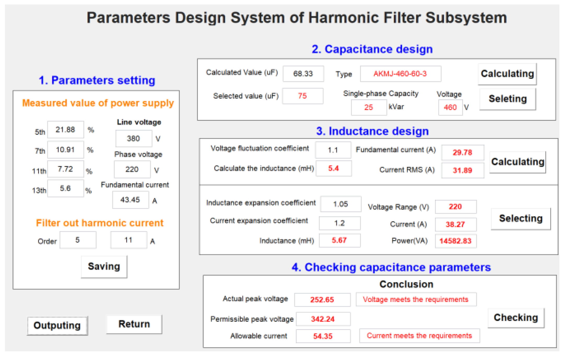
3.5. Parameter Design System of HFSS

For the calculation of various design parameters of the filter, Matlab graphical user interface development environment (GUIDE) is adopted to design the parameter design system of HFSS. The design method is to first add the required components in GUIDE according to the needs of parameter design, then set the properties of each component, then write the callback function program according to the parameter design method of HFSS, and finally complete the debugging and improvement of the program. Based on the requirements of HFSS parameter design, the parameter design system is mainly composed of five modules: filter parameter setting, capacitor design, inductance design, checking capacitance parameters, and result output. Figure 3 shows the GUI of the parameter design system of HFSS.
In Figure 3, the buttons are associated with various callback functions (by setting the buttons’ properties), and the functions can be performed by pressing the corresponding buttons. The main functions of five modules are as follows.
  • Parameters setting module
This module is responsible for setting various parameters of the filter, such as harmonic order, the magnitude of each harmonic current, the line voltage and phase voltage of the system, etc.
  • Capacitor design module
According to the harmonic order, the magnitude of the harmonic current in the system, and the minimum capacitance of filter capacitor, this module calculates the optimal capacity of filter capacitor so as to determine its capacitance. On this basis, the module selects the type of filter capacitor and then calculates its parameters, including capacitance (uF), nominal voltage (V), and capacitor capacity (kVar).
  • Inductance design module
According to the magnitude of the fundamental current and the capacitance of the filter capacitor, this module calculates the parameters of the electromagnetic coupling reactor, including inductance, current, voltage, and capacity.
  • Checking capacitance parameters module
This module checks whether the rated voltage and rated current of the filter capacitor meet the requirements.
  • Result output module

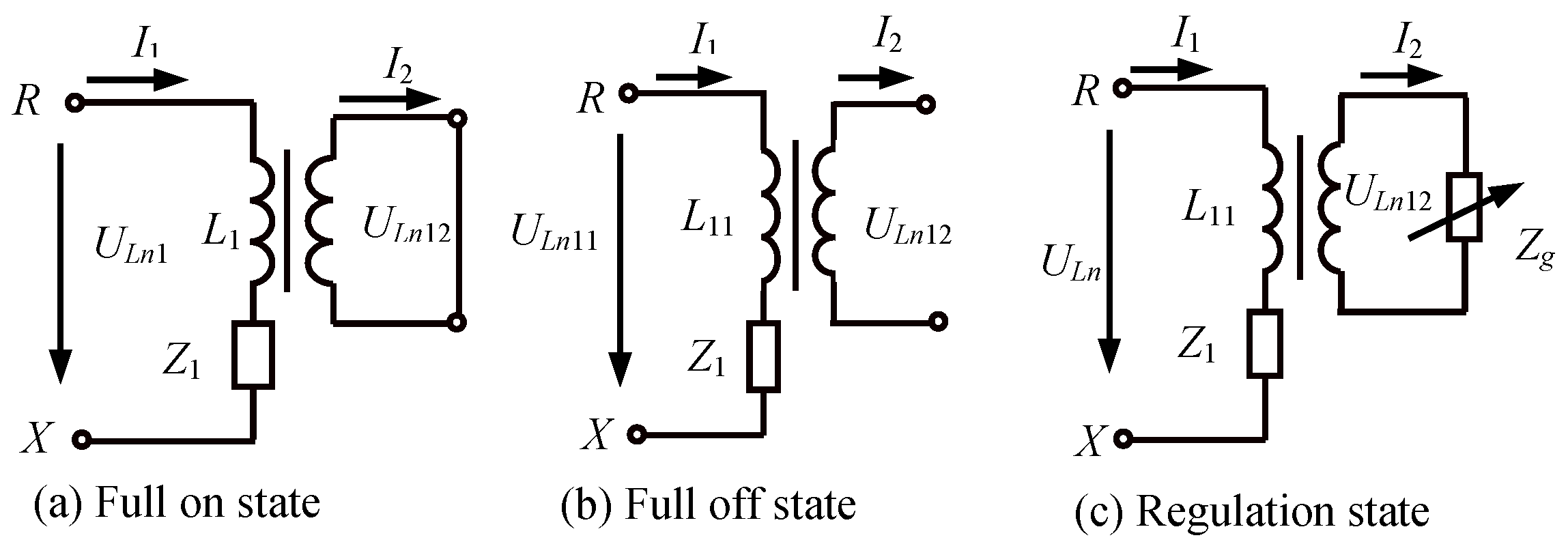
3.6. Inductance Regulation of Electromagnetic Coupling Reactor

Based on the structure of a traditional core reactor, the core reactor with single winding is designed as SS with primary reactance windings ( W 1 ) and secondary reactance windings ( W 2 ). Its secondary reactance winding access impedance conversion circuit (PEIC). Its topological structure is shown in Figure 4.
In Figure 4, PEIC is composed of an anti-parallel thyristor, which has three working states: full on, full off, and regulation. Taking R phase as an example, the equivalent circuit of SS is shown in Figure 5.
In Figure 5, U L n 11 and U L n 12 are the terminal voltages of W 1 and W 2 of SS, respectively; I 1 and I 2 are the currents flowing through W 1 and W 2 , respectively. As shown in Figure 5a, when the thyristor is fully turned on, W 2 is equivalent to a short circuit. In this case, i 2 is the largest, and so is i 1 , so the equivalent inductance of SS is the smallest. As shown in Figure 5b, when the thyristor is fully turned off, W 2 is equivalent to an open circuit. In this case, i 2 is the smallest, and so is i 1 , so the equivalent inductance of SS is the largest. It can be seen from Figure 5c that when the thyristor is in normal operation, the thyristor circuit shifts between off and on during a power cycle.
According to the principle of electromagnetic transformation, there is
Z 1 = U L n 11 I 1 = K U L n 12 I 2 / K = K 2 U L n 12 I 2 = K 2 Z g
Set the voltage across PEIC is:
u 2 = 2 U L n 12 sin ω t
Z is assumed to be the equivalent impedance of W 2 in the regulation state, then the positive and negative half-waves of current waveform of W 2 are symmetrical. From the Fourier transform formula, we can get:
i 2 = U L n 12 sin 2 α + ( π α ) sin 2 α + ( π α ) 2 π Z g
where Z g is the equivalent impedance of PEIC:
Z g = π Z sin 2 α + ( π α ) sin 2 α + ( π α ) 2
The equivalent impedance of W 1 :
Z 1 = K 2 π Z sin 2 α + ( π α ) sin 2 α + ( π α ) 2
So the equivalent inductance of W 1 (the primary inductance of SS) is:
L 11 = Z 1 2 π f 1
The following conclusions can be drawn from Equations (29) and (30):
  • When α = 0 , the thyristors are fully turned on, in which case the primary inductance of SS is the minimum, denoted by L 1 k .
  • When α = 180 , the thyristors are fully switched off, in which case the primary inductance of SS is the maximum, denoted by L 1 m .
  • The inductance of SS ranges within [ L 1 k , L 1 m ]. By adjusting the trigger angle α of the thyristor, the primary inductance of SS can be continuously adjusted in this range, and its value will increase with the rising trigger angle α .
  • When π 2 α < 5 π 6 , the linearity of the primary inductance is relatively good, so it is the optimal regulation range.
  • The variation of the magnetic circuit of SS is complex and thus difficult to control quantitatively.
In summary, the controller can set the initial trigger angle to 0 according to the relationship between the inductance (impedance) and the trigger angle α . Then it adjusts the trigger angle α according to the required control signal U z to change the inductance L 11 of SS, so that the HFSS is in series resonance with the assistance of equivalent filter capacitor C 1 , thereby realizing dynamic tuning and optimizing the filtering effect.

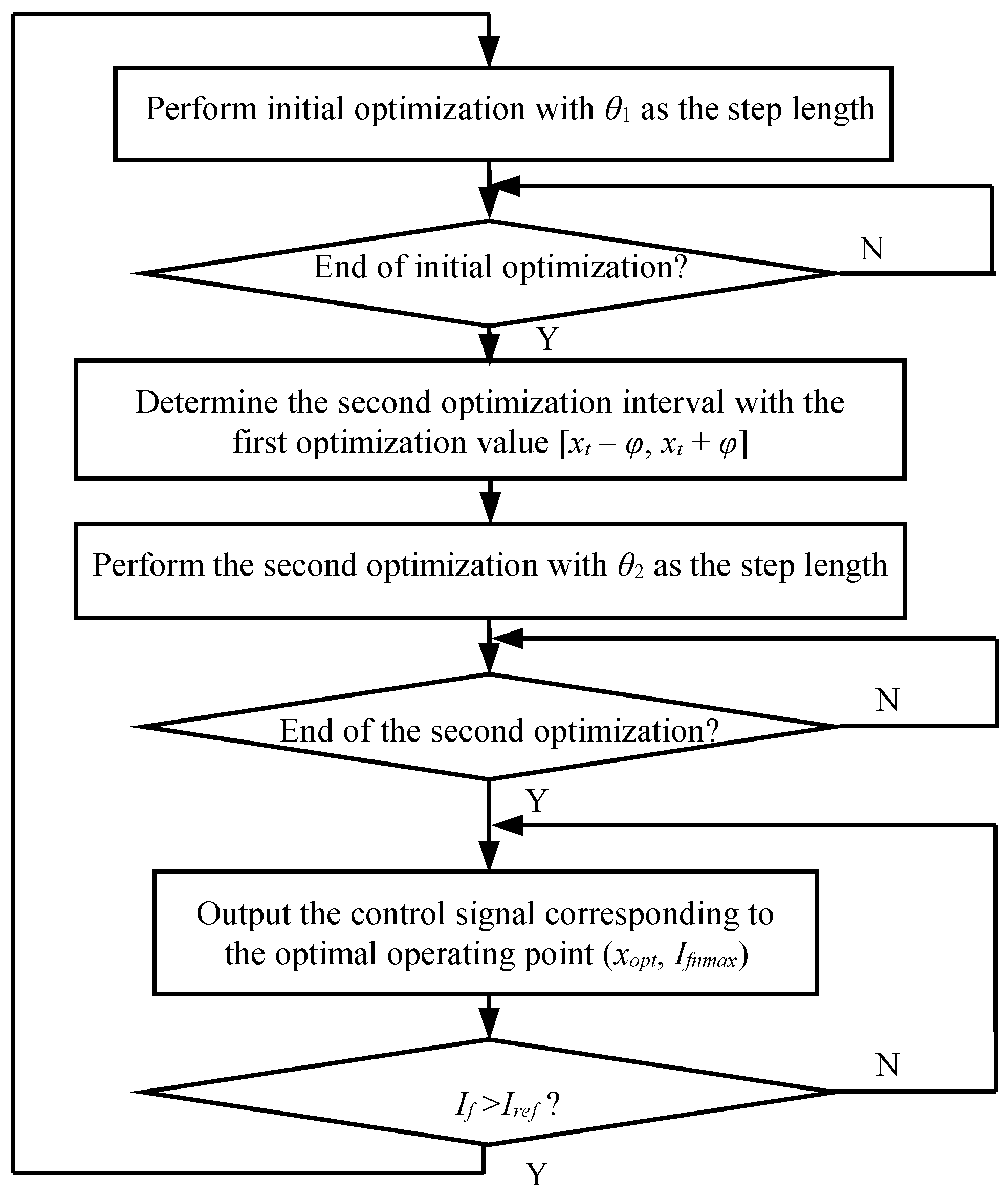
3.7. Two-Step Optimization Algorithm

Assuming that the control signal U z is x, the h-order harmonic current I f ( h ) that needs to be filtered is the control objective, and that I f ( h ) and x have a function relationship of I f ( h ) = f ( x ) , the tuning process of HFSS can be regarded as solving the optimal solution x o p t corresponding to I f ( h ) at its maximum I f m a x .
For the HFSS, the harmonic h-order and the capacity of the filter capacitor is generally fixed, so its tuning is mainly realized by adjusting the equivalent reactance L 11 of the primary reactance winding of SS. The value of L 11 is mainly adjusted by controlling the trigger angle α of the thyristor, whose effective range is α = 30 . Therefore, assuming that the control signal corresponding to α = 30 is x 0 , and that to α = 150 is x, the change range of the control signal is [ x 0 , x n ].
During the operation of HFSS, the harmonic current I h generated by the harmonic source load will change with the working conditions, the frequency of the power grid will sometimes fluctuate, and the system impedance will vary occasionally. After the HFSS is switched on, the h-order harmonic current flowing into the HFSS branch is I f ( h ) . The approximate curve of I f ( h ) varying with the control signal x in a certain period of time is shown in Figure 6.
It can be seen from Figure 6 that the curve of the harmonic current I f ( h ) is characterized by random, time-varying, and non-linear features. It has no unimodality; instead, there are multiple extreme points. Thus, based on the control objective of HFSS, i.e., h-order harmonic current I f ( h ) , this paper adopts a two-step optimization algorithm to solve the optimal solution x o p t corresponding to I f ( h ) at its maximum I f m a x .
  • Principle of two-step optimization algorithm.
Initial optimization: The optimization interval is [ x 0 , x n ], and the optimization step length is θ 1 ; that is, the initial value of the control signal is x 0 . Then, through a consecutive increment of θ 1 , the point ( x t , I f t ) at which I f ( h ) reaches the maximum under this step length is found.
Second self-optimizing: The optimization interval is [ x t θ , x t + θ ] and the optimization step length is θ 2 ( θ 2 < θ 1 ) ; that is, the initial value of the control signal is x t θ . Then, through a consecutive increment of θ 2 , the point ( x o p t , I f m a x ) at which I f ( h ) reaches the maximum with this step length is found. This point is the optimal operating point in a certain period of time.
  • Advantages of two-step optimization algorithm.
The step length θ 1 of initial optimization is large, so it takes a short time to find the operating point ( x t , I f t ) at which I f ( h ) maximizes. However, this point may not be the optimal operating point due to the large step length. For this reason, another smaller step length θ 2 is adopted to perform the second self-optimization in the interval [ x t φ , x t + φ ] with x t as the center and φ as the radius. In this way, the optimization time is shortened and the optimization accuracy is improved. Generally, θ 2 = (0.1 0.5) θ 1 .
  • Process of two-step optimization algorithm.
According to the control objective and two constraints of HFSS, the specific process of the two-step optimization algorithm is shown in Figure 7.

4. Reactive Power Compensation Method of RPCSS

Through the power factor of the system before compensation and the power factor after compensation, the required reactive power compensation capacity Q c s j can be calculated. On this basis, the reactive power capacity provided by the reactive power compensation subsystem (RPCSS) can be obtained to determine the capacitance of the compensator bank C 2 . By controlling the on/off of contactors KM 21 –KM 2 n , the capacitor C 21 C 2 n is switched on in groups to generate reactive power.
According to Figure 1, when KM 1 is disconnected and KM 2 is closed, the RPCSS is put into operation. To realize reactive power compensation, the following equation must be satisfied:
Q S = Q F Q p Q C 2
where Q S is the reactive power of the system, Q F is the reactive power of the load, Q C 2 is the reactive power provided by the RPCSS, and Q p is the fundamental reactive power compensated for the distribution system when the HFSS is in series resonance.

4.1. Capacitance Determination of Reactive Power Compensation Capacitor

After the RPCSS is put into operation, the phase angle between the voltage and the current decreases from φ 1 to φ 2 , and the power loss is reduced.
  • Required reactive power compensation capacity.
Based on the active power P a v and power factor cos φ 1 of the system before compensation as well as the power factor cos φ 2 after compensation, the required reactive power compensation capacity Q c s j can be calculated:
Q c s j = P a v tan φ 1 tan φ 2 = P a v 1 cos φ 1 2 cos φ 1 1 cos φ 2 2 cos φ 2
  • The total reactive power capacity provided by RPCSS.
In practical engineering applications, the capacity of capacitor can only be a multiple of 5, so it is set according to the following formula:
Q C 2 = c e i l [ Q c s j Q P / 5 ] × 5
  • The equivalent capacitance C 2 of RPCSS.
C 2 = Q C 2 2 π f 1 U C N 2

4.2. Control Strategy of RPCSS

The capacitance of RPCSS to the system is regulated by controlling the on/off of contactors. The specific capacitance is determined according to the actual situation of the system. If the number of compensator groups is n, the level number n shall meet the following equation:
N = C n 1 + C n 2 + C n 3 + + C n n = 2 n 1
Regardless of the same level number, it can be seen from Equation (35) that n groups of capacitor banks have a total of 2 n 1 level number, which makes up for the disadvantage of single capacitance of traditional PPF and enlarges the compensation range.
For the switching control of n groups of compensators, when a single power factor index is selected as the switching standard, it is easy to reduce the service life of the compensator resulted from frequent switching of the compensator, cause switching oscillations, and affect the operation of other equipment. Therefore, an appropriate control strategy should be adopted so that the compensator can switch on and off smoothly and so that the system’s reactive power is maintained within the range of national standards.
The range of the target power factor selected is:
Δ p h = p h max p h min
where p h m a x is the maximum target power factor and p h m i n is the minimum target power factor which can be selected based on actual enterprise requirements; for example, Δ p h = 1 0.9 = 0.1 . Δ p h is the control variable for evaluating the effect of reactive power compensation, and it improves the frequent switching caused by a single value as the control standard. The real-time power factor deviation of the system is:
Δ p h 0 = p h max p h 0
where p h 0 is the measured real-time power factor. The switching strategy of compensator is:
  • When 0 < Δ p h 0 Δ p h , the reactive power of the system conforms to the standard, and the reactive power compensation is maintained;
  • When Δ p h 0 > Δ p h , the system is in an under-compensated state. The controller switches on the compensators in groups according to the principle that the actual capacity of compensator should be equal or slightly higher than the required theoretical capacity Q C 2 obtained from Equations (32) and (33) to make.

5. Integration Simulation of Harmonic Suppression and Reactive Power Compensation

5.1. Simulation Cases Design

By switching the on/off state of KM 1 and KM 2 in Figure 1, three simulation cases are designed to analyze the load characteristic, harmonic suppression effect, reactive power compensation effect, and comprehensive effect of harmonic suppression and reactive power compensation, as shown in in Table 1. In the table, “0” means that the contactor is off, and “1” means that the contactor is on.

5.2. Load Characteristic Analysis

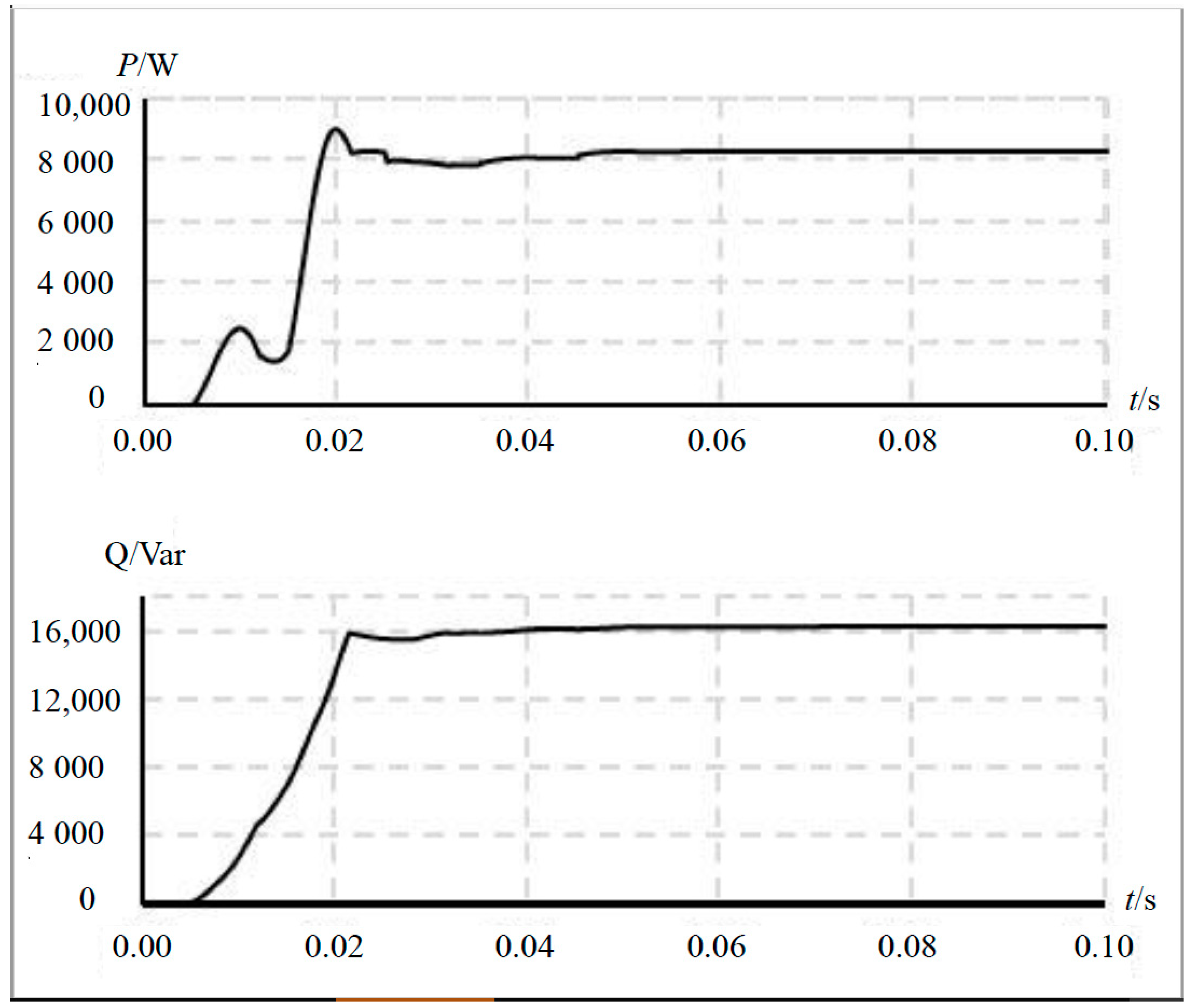
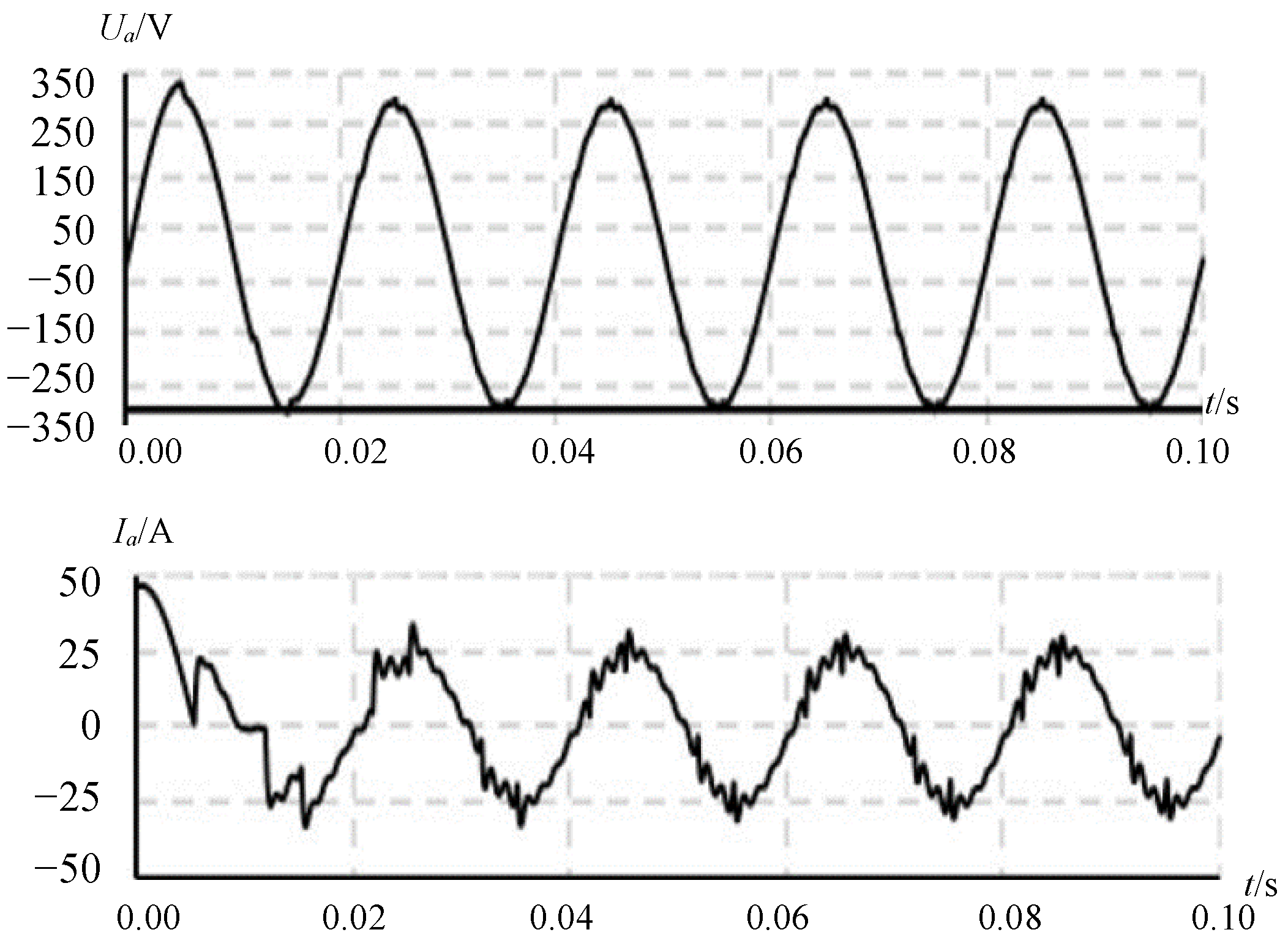
  • Scheme I: According to the power quality parameters of a power plant’s distribution network and the simulation model of the integrated system of harmonic suppression and reactive power compensation, the system simulation time of the system is set to 0.1 s after several experiments. The connection mode of the three-phase power supply adopts a star connection, and RMS of the line voltage is 380 V. The frequency is 50 Hz; in the series RLC circuit, R = 1 Ω , L = 5 mH, and C = 0 ; the sampling time T s = 1 / 512 / 50 3.906 × 10 5 s.
In the NL simulation model, different load characteristics can be obtained by changing the phase shift angle of the pulses ( β ), resistance R L ( Ω ) and inductance H L (mH). Herein, under R L = 5 Ω and H L = 30 mH, the phase shift angle of β varies within 0–85 (every increment of 5 ), and then the reactive power data of the system can be obtained.
With the load characteristic simulation and analysis system developed in this paper (see Figure 8), the reactive power and harmonic characteristic simulation results are obtained, as shown in Table 2 and Table 3, respectively.
In order to verify the effectiveness of the method proposed in this paper, a power distribution system with small harmonic voltage distortion rate, small power factor, and larger harmonic current, i.e., Case I-13, is selected as the research object of this paper. The waveforms of active power and reactive power of the system are shown in Figure 9.
In Figure 9, P and Q, respectively, are the active power and the reactive power of the system. Figure 10 shows the waveforms of the voltage and current in the system.
In Figure 10, U a and I a , respectively, are the single-phase voltage and current on the system. The waveform of the phase voltage U a is roughly sinusoidal and symmetrical, with small distortion, but the waveform of the phase current I a is not sinusoidal and non-symmetrical because of the large distortion. Its harmonic spectrum is shown in Figure 11.
The following conclusions can be drawn from the data of Case I-13 in Table 2 and Table 3, waveforms in Figures Figure 10 and Figure 11:
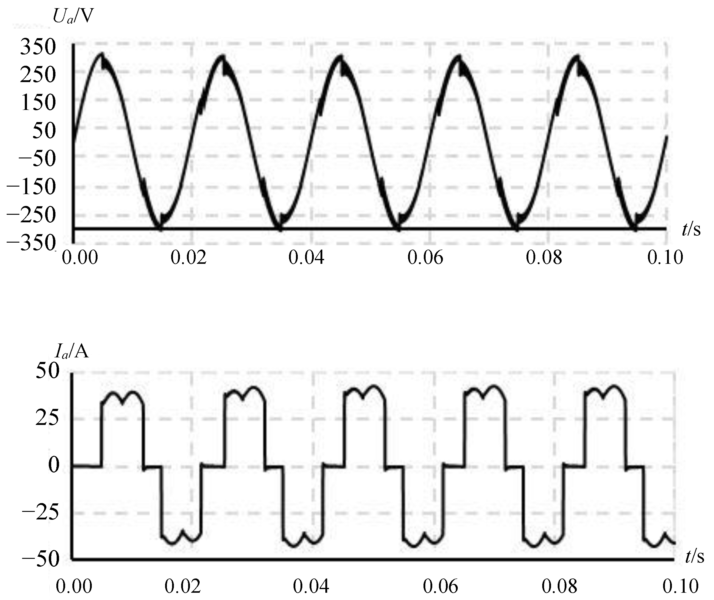
  • In case of the phase shift angle of the pulses ( β ) of 60 , the active power P is 8309 W, the reactive power Q is 13,276 Var, and the power factor is 0.4547. In this case, the power factor is too small, so reactive power compensation is required;
  • The waveform distortion of the current in the system is great. The main harmonics exceeding the harmonic current standard are the 5th, 7th, 11th, and 13th harmonics, which need to be filtered.

5.3. Harmonic Suppression Effect Analysis

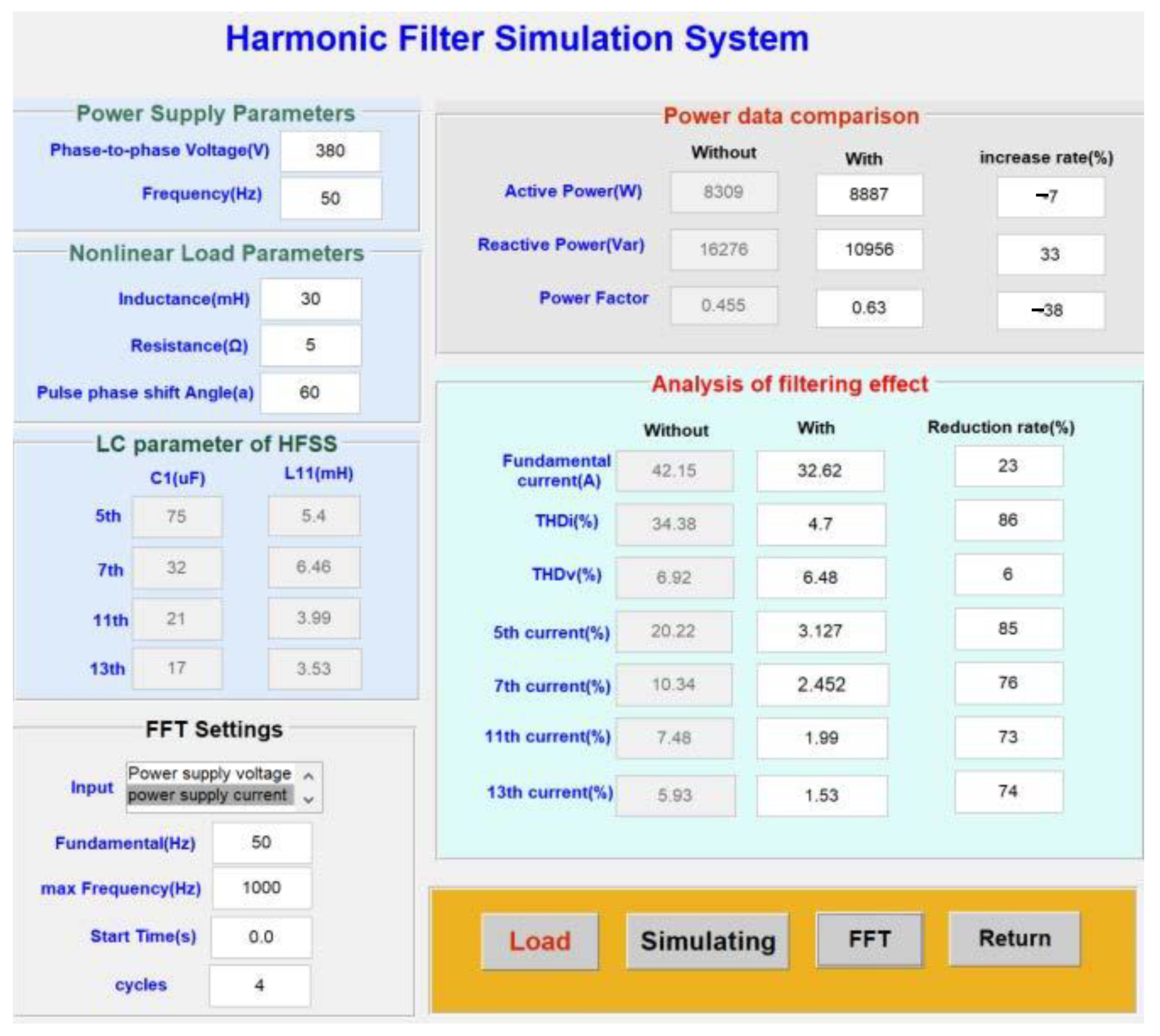
  • Scheme II: Only HFSS is put into operation to analyze the suppression effect of HFSS on the harmonics in distribution network in Case I-13. The active power and reactive power and power factor before and after filtering are also analyzed for the next dynamic reactive power compensation.
With the harmonic parameters (Case I-13) in Table 3, as well as the HFSS parameters design and simulation system, the LC parameters of HFSS that filter harmonic current I s d are obtained, as shown in Table 4.
According to the design parameters in Table 4, the harmonic filter simulation system developed in this paper (see Figure 12) is used for traditional filtering simulation. Voltage and current waveforms on the system after applying HFSS are shown in Figure 13.
It can be observed from Figure 13 that after filtering out the 5th, 7th, 11th, and 13th harmonics, the current waveforms for the system are basically sinusoidal and symmetrical. Compared with the current waveform in Figure 10, the current distortion is greatly reduced, the amplitude of oscillations is reduced, and the overall waveform is smoother. The harmonic data and power data before and after application of HFSS are shown in Table 5 and Table 6, respectively.
The reduction rate Y in Table 5 and Table 6 is given by
Y = 1 X 1 X 0 100
where X 1 and X 0 are, respectively, the simulation data before and after HFSS is put into operation. A negative value of Y indicates the rate of increase. The following conclusions can be drawn from Table 5 and Table 6 and Figure 13:
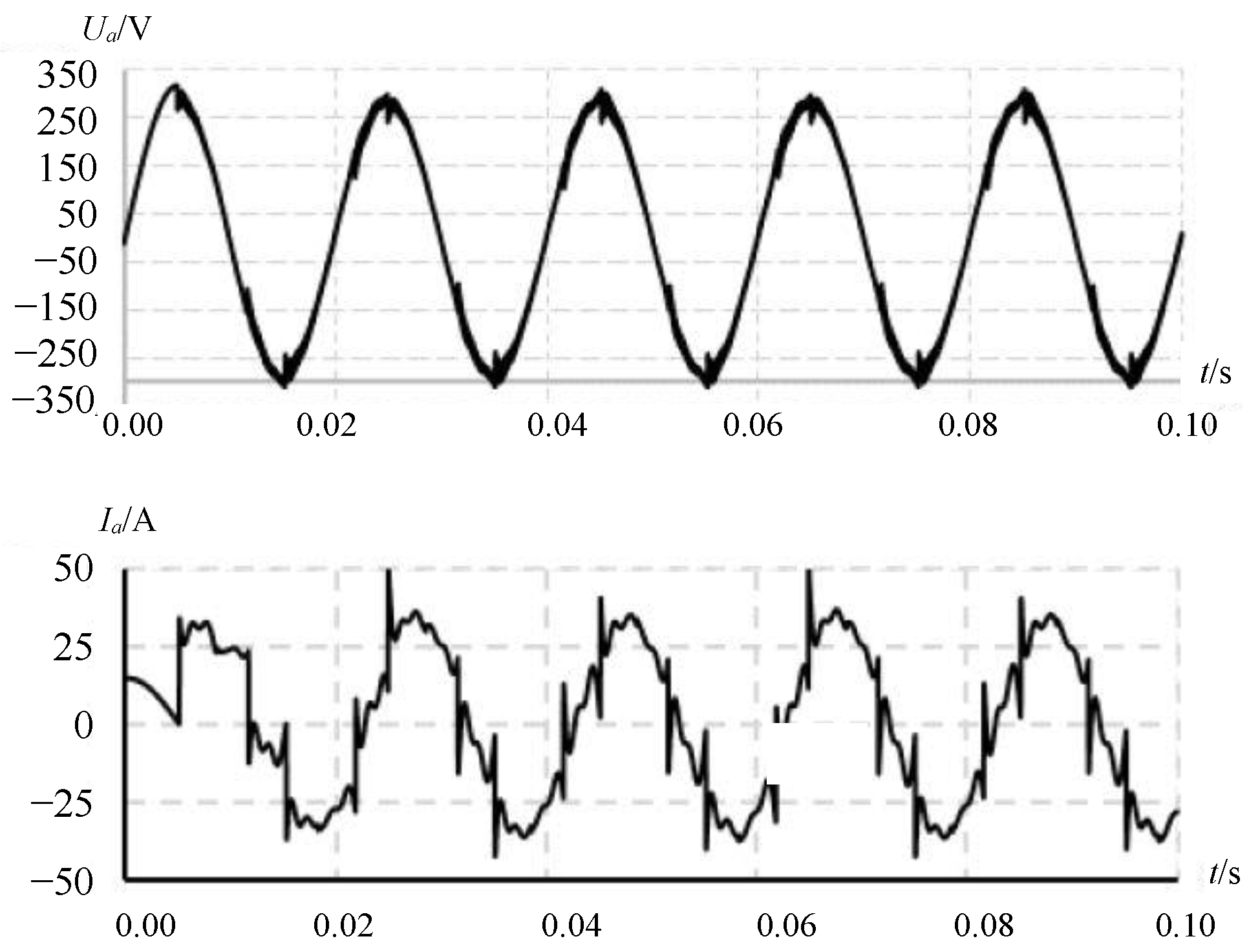
  • In Case I-13, after HFSS is put into use, the harmonic currents of the main orders all drop significantly (all above 70%), and the main harmonic current content of the system falls below the national standard. This indicates a significant filtering effect and verifies the rationality of filter parameter design;
  • The reactive power reduction rate of the system is about 30%, and the power factor improvement rate is 38%, indicating that the HFSS has a certain effect in reactive power compensation. However, the filtered power factor is still not up to the requirements, so it is necessary to use RPCSS to compensate the system so that the power factor can reach 0.98 or more.

5.4. Analysis of the Comprehensive Effect of Harmonic Suppression and Reactive Power Compensation

  • Scheme III: On the basis of Scheme II, the reactive power compensation subsystem (RPCSS) is added to analyze the active power, reactive power, and power factor of the system.
It can be seen from Table 6 that the power factor of the filtered system is 0.63, and the active power is 10,956 W. From Equations (33) and (34), the required capacity Q C 2 of the system’s compensator is obtained: 20 kVar, and its capacitance C 2 is 300 µF.
Waveforms of active power, reactive power and power factor of the system after applying HFSS and RPCSS are shown in Figure 14. The voltage and current waveforms on the power supply side after applying HFSS and RPCSS are shown in Figure 15.
The harmonic data and power data before and after applying HFSS and RPCSS are shown in Table 7 and Table 8, respectively.
From Figure 13 and Figure 15, and Table 7 and Table 8, the following conclusions can be drawn.
  • After HFSS and RPCSS are used, the reactive power of the system is reduced from 16,276 to 1626 Var, with a reduction rate of 90%, and the power factor increases from 0.45 to 0.99. These indicate that the capacitive reactive power and inductive reactive power are roughly balanced, and that the compensation effect is obvious;
  • After filtering the 5th, 7th, 11th, and 13th harmonic currents, the current distortion rate is reduced to below 5%, and the reduction rate ranges from 50% to 80%. Moreover, the voltage distortion rate is also reduced by 60% and the harmonic voltage of the power supply is sinusoidal and symmetrical, indicating an obvious filtering effect;
  • When there are harmonics in the distribution network, HFSS should be applied for filtering first until the harmonics in the system meet the national regulations. After that, RPCSS is used for reactive power compensation;
  • After the comprehensive treatment is completed, HFSS is put into operation first and then switched off later to avoid the harmonic amplification caused by the direct input of RPCSS, the burn out of main power components of RPCSS, and the system oscillation, so as to ensure the smooth operation of the system.

6. Conclusions

Aiming at the serious harmonic pollution and the low power factor in the distribution network of industrial enterprises, a novel integrated method for harmonic suppression and reactive power compensation has been devised. The integrated method realizes the dual functions of harmonic filtering and reactive power compensation and filters out harmonics while ensuring safe operation of the power compensator. A method for designing the capacity of filter capacitor and the rated parameter of electromagnetic coupling reactance converter has been proposed, and an optimization simulation system has been constructed. The simulation system has been developed and the simulation has been finished. After the treatment, the power factor increased from 0.45 to 0.99, the 5th, 7th, 11th, and 13th harmonic currents, and the current distortion rate been reduced to below 5%, which all meet the national standards. The integrated method could dynamically track harmonics and reactive power changes, filter out harmonics, and improve the power factor and the symmetry level of the power source. Simulation results have verified that the HFSS is put into operation first and then switched off later to ensure the normal operation of other equipment in the distribution network. The research results lay a certain theoretical and technical foundation for the harmonic filtering and reactive power compensation theory, technology, and its device innovation to achieve effective suppression of power harmonics and reactive power compensation. The future development direction of harmonic suppression and reactive power compensation in distribution network will be to seek the development of core components, and try to replace filters and reactive power compensators. The harmonic suppression and reactive power compensation device with high reliability developed by using the method proposed in this paper can filter harmonics first and then compensate reactive power to improve power factor and realize energy saving. It will produce certain economic benefits.

Author Contributions

Y.W. contributed to the conception of the study, the background research, method design and experimental results analysis, and wrote the manuscript; K.Y. helped perform the analysis with constructive suggestions; Y.Y. and H.L. provided an important suggestion about the framework of this paper and revised the manuscript. All authors have read and agreed to the published version of the manuscript.

Funding

This work was supported by the Fundamental Research Funds for the National Natural Science Foundation of China under Grant [61703318].

Institutional Review Board Statement

Not applicable.

Informed Consent Statement

Not applicable.

Data Availability Statement

Not applicable.

Conflicts of Interest

The authors declare no conflict of interest.

References

  1. Li, D.; Yang, K.; Zhu, Z.Q.; Qin, Y. A Novel Series Power Quality Controller with Reduced Passive Power Filter. IEEE Trans. Ind. Electron. 2017, 64, 773–784. [Google Scholar] [CrossRef]
  2. Lee, T.L.; Wang, Y.C.; Li, J.C.; Guerrero, J.M. Hybrid active filter with variable conductance for harmonic resonance suppression in industrial power systems. IEEE Trans. Ind. Electron. 2015, 62, 746–756. [Google Scholar] [CrossRef] [Green Version]
  3. Azebaze Mboving, C.S. Investigation on the Work Efficiency of the LC Passive Harmonic Filter Chosen Topologies. Electronics 2015, 10, 896–930. [Google Scholar] [CrossRef]
  4. Dovgun, V.P.; Egorov, D.E.; Shevchenko, E.S. Parametric synthesis of passive filter-compensating devices. Russ. Electri. Eng. 2016, 87, 28–34. [Google Scholar] [CrossRef]
  5. Bollen, M.H.; Das, R.; Djokic, S.; Ciufo, P.; Meyer, J.; Rönnberg, S.K.; Zavodam, F. Power quality concerns in implementing smart distribution-grid applications. IEEE Trans. Smart Grid 2017, 8, 391–399. [Google Scholar] [CrossRef] [Green Version]
  6. Kalaskar, M.N.R.; Holmukhe, M.R. Report On Harmonics Generation and Mitigation in Power System. Int. J. Eng. Res. 2016, 5, 772–774. [Google Scholar]
  7. Chen, J.; Xiao, L.; Yuan, Y.X.; Yang, K.; Lei, L.; Mao, B.P.; Chen, Z. Development of passive dynamic power filter based on MCU. J. Wuhan Univ. Technol. 2013, 35, 144–146. [Google Scholar]
  8. Wang, Y.; Yuan, Y.; Chen, J. Study of harmonic suppression of ship electric propulsion systems. J. Power Electron. 2019, 19, 1303–1314. [Google Scholar]
  9. Wang, Y.F.; Yuan, Y.X. Development of a Soft Starter with Current-Limiting, Reactive Power Compensation and Harmonic Filtering. Appl. Mech. Mater. 2014, 462–463, 658–661. [Google Scholar] [CrossRef]
  10. Wang, Y.F.; Yuan, Y.X.; Chen, J.; Cheng, Q.J. A Dynamic Reactive Power Compensation Method of Super High-Power and High-Voltage Motor. Appl. Mech. Mater. 2014, 602–605, 2828–2831. [Google Scholar] [CrossRef]
  11. Wang, Y.F.; Yuan, Y.X. A dynamic reactive power compensation method for high-power and high-voltage electronic motors based on self-adaptive fuzzy PID control. In Proceedings of the 2016 IEEE Chinese Guidance, Navigation and Control Conference (CGNCC), Nanjing, China, 12–14 August 2016; pp. 10–15. [Google Scholar]
  12. Kalair, A.; Abas, N.; Kalair, A.R.; Saleem, Z.; Khan, N. Review of harmonic analysis, modeling and mitigation techniques. Renew. Sust. Energ. Rev. 2017, 78, 1154–1187. [Google Scholar] [CrossRef]
  13. Zobaa, A.F. Mixed-Integer Distributed Mixed-Integer Distributed Ant Colony Multi-Objective Optimization of Single-Tuned Passive Harmonic Filter Parameters. IEEE Access 2019, 7, 44862–44870. [Google Scholar] [CrossRef]
  14. Othman, A.M.; Gabbar, H.A. Enhanced microgrid dynamic performance using a modulated power filter based on enhanced bacterial foraging optimization. Energies 2017, 10, 776. [Google Scholar] [CrossRef] [Green Version]
  15. Swain, S.D.; Ray, P.K.; Mohanty, K.B. Improvement of power quality using a robust hybrid series active power filter. IEEE Trans. Power Electr. 2016, 32, 3490–3498. [Google Scholar] [CrossRef]
  16. Omar, R.; Tan, Z.H.; Rasheed, M.; Sulaiman, M. An Improvement of Shunt Active Power Filter using Effective Controller for Different Load Condition. J. Eng. Appl. Sci. 2020, 15, 1311–1321. [Google Scholar] [CrossRef] [Green Version]
  17. Litrán, S.P.; Salmeron, P. Analysis and design of different control strategies of hybrid active power filter based on the state model. IET Power Electron. 2012, 5, 1341–1350. [Google Scholar] [CrossRef]
  18. Schffer, G.J.; Moura, F.A.M.; Mendonça, M.V.B.; Júnior, A.J.P.R.; Albertini, M.R.M.C.; Camacho, J.R. Conservative Power Theory (CPT): A New Approach to the Tuned Passive Filter Design. Renew. Energ. Power Qual. J. 2019, 17, 245–250. [Google Scholar] [CrossRef]
  19. Song, Q.; Chen, S.; Zhao, Z.; Liu, Y.; Alsaadi, F.E. Passive filter design for fractional-order quaternion-valued neural networks with neutral delays and external disturbance. Neural Netw. 2021, 137, 18–30. [Google Scholar] [CrossRef]
  20. Wang, Y.; Yuan, Y.; Chen, J. A novel electromagnetic coupling reactor based passive power filter with dynamic tunable function. Energies 2018, 11, 1647. [Google Scholar] [CrossRef] [Green Version]
  21. Solatialkaran, D.; Khajeh, K.G.; Zare, F. A Novel Filter Design Method for Grid-Tied Inverters. IEEE Trans. Power Electr. 2021, 36, 5473–5485. [Google Scholar] [CrossRef]
  22. Ortuzar, M.E.; Carmi, R.E.; Dixon, J.W.; Moran, L. Voltage-source active power filter based on multilevel converter and ultracapacitor DC link. IEEE Trans. Ind. Electron. 2006, 53, 477–485. [Google Scholar] [CrossRef]
  23. Alasali, F.; Nusair, K.; Foudeh, H.; Holderbaum, W.; Vinayagam, A.; Aziz, A. Modern Optimal Controllers for Hybrid Active Power Filter to Minimize Harmonic Distortionk. Electronics 2022, 11, 1453. [Google Scholar] [CrossRef]
  24. Tomaszm, B.; Marekm, N.; Stanisławm, P. Power Supply and Reactive Power Compensation of a Single-Phase Higher Frequenc. Energies 2022, 15, 2563. [Google Scholar]
  25. Sun, L.; Zhang, Z.; Gu, X.; Yu, L. Analysis of Reactive Power Compensation Effect of a New Hybrid Excitation. IEEE Trans. Ind. Electron. 2020, 67, 3562–3572. [Google Scholar] [CrossRef]
  26. Teleke, S.; Abdulahovic, T.; Thiringer, T. Dynamic performance comparison of synchronous condenser and SVC. IEEE Trans. Power Deliv. 2008, 23, 1606–1612. [Google Scholar] [CrossRef]
  27. Funaki, T.; Nakagawa, K.; Hikihara, T. The Origin of Nonlinear Phenomena in TCR-SVC Associated With Parametric Excitation of Intrinsic Oscillation and External Excitation. IEEE Trans. Circuits Syst. I Regul. Pap. 2008, 55, 2952–2958. [Google Scholar] [CrossRef] [Green Version]
Figure 1. Equivalent harmonic circuit of the filter system.
Symmetry 14 01347 g001
Figure 2. Schematic diagram for the h-order harmonic current flow.
Symmetry 14 01347 g002
Figure 3. GUI of the parameter design system of HFSS.
Symmetry 14 01347 g003
Figure 4. Topological structure of SS.
Symmetry 14 01347 g004
Figure 5. Equivalent circuit of SS (R phase).
Symmetry 14 01347 g005
Figure 6. Approximate curve of I f varying with the control signal.
Symmetry 14 01347 g006
Figure 7. Process of the two-step optimization algorithm.
Symmetry 14 01347 g007
Figure 8. GUI of load characteristic simulation and analysis system.
Symmetry 14 01347 g008
Figure 9. Waveforms of active power and reactive power on the system (Case I-13).
Symmetry 14 01347 g009
Figure 10. Waveforms of the voltage and current on the system (Case I-13).
Symmetry 14 01347 g010
Figure 11. Harmonic frequency spectrum of the current on the power supply side.
Symmetry 14 01347 g011
Figure 12. GUI of harmonic filter simulation system.
Symmetry 14 01347 g012
Figure 13. Waveforms of the voltage and current on the system (Case I-13).
Symmetry 14 01347 g013
Figure 14. Waveforms of active power, reactive power, and power factor of the system after applying HFSS and RPCSS.
Symmetry 14 01347 g014
Figure 15. Voltage and current waveforms on the power supply side after applying HFSS and RPCSS (Case III).
Symmetry 14 01347 g015
Table 1. Simulation cases.
CaseSchemeKM 2 KM 1 Simulation Model Applied
ILoad characteristic analysis0 0Without
IIharmonic suppression effect analysis0 1HFSS
IIIanalysis of the integration system1 1HFSS + RPCSS
Table 2. Reactive power characteristic simulation results (Scheme I).
Case β / P/WQ/Varph
I-1032,0564670.9999
I-2531,82513720.9991
I-31031,19332970.9945
I-41529,83863510.9781
I-52027,74198090.9428
I-62525,48612,5840.8967
I-73023,22414,5160.8480
I-83520,46616,2970.7823
I-94017,78117,3670.7154
I-104514,97117,7570.6446
I-115011,83617,5950.5581
I-1255926516,6590.4860
I-1360830916,2760.4547
I-1465716415,3370.4232
I-1570497813,5170.3456
I-1675304311,0500.2655
I-1780150376600.1925
I-188550640590.1238
Table 3. Harmonic characteristic simulation results (Scheme I).
Case β / I 1 ( A ) THD i / % I 5 / % I 7 / % I 11 / % I 13 / % I 17 / % THD v / %
I-1086.9123.6618.5612.296.094.361.928.39
I-2586.5626.0519.2613.237.455.923.629.23
I-31085.5529.1619.9113.978.667.355.3110.26
I-41583.4030.6720.5613.729.277.316.0311.40
I-52080.3831.0820.6713.599.197.325.9413.29
I-62577.2031.0920.8513.419.207.275.9414.53
I-73073.4331.1721.1513.139.277.095.9911.94
I-83569.1431.0821.2812.959.197.095.8912.68
I-94064.3031.0021.3212.838.977.175.6910.06
I-104558.7031.1421.7712.409.106.985.839.94
I-115052.5031.2922.2811.959.286.805.999.03
I-125546.0531.2522.4611.818.956.905.606.72
I-136042.1534.3820.2210.347.485.933.826.92
I-146540.1031.5623.2911.059.276.515.886.59
I-157033.2231.7424.0710.259.136.315.725.24
I-167526.0531.9925.169.158.766.275.224.05
I-178017.8134.3528.476.009.275.085.412.65
I-188543.83405936.391.7910.222.136.031.57
Table 4. HFSS design parameters (Case I-13).
Order I sd / A C 1 / uF 3 Q C 1 / Var L 11 / mH I L 1 / A P n / VA
5th1175255.6738.2714,583.00
7th632156.7825.089557.00
11th421154.1924.869472.93
13th317153.7127.839761.50
Table 5. Harmonic data before and after application of HFSS.
Case I 1 / A T H D i / % I 5 / % I 7 / % I 1 1 / % I 1 3 / % T H D V / %
I-1342.1534.3820.2210.347.485.936.92
II32.624.73.132.451.991.536.48
Reduction rate/%2386857673746
Table 6. Power data before and after application of HFSS.
Case P / W Q / Varph
I-13830916,2760.45
II888710,9560.63
Reduction rate/%−733−38
Table 7. Harmonic data before and after applying HFSS and RPCSS.
Case I 1 / A T H D i / % I 5 / % I 7 / % I 1 1 / % I 1 3 / % T H D V / %
I-1342.1534.3820.2210.347.485.936.92
III25.357.433.984.553.552.5632.79
Reduction rate/%40788056535760
Table 8. Power data before and after applying HFSS and RPCSS.
Case P / W Q / Varph
I-13830916,2760.45
III11,17016260.99
Reduction rate/%−3490−120
Publisher’s Note: MDPI stays neutral with regard to jurisdictional claims in published maps and institutional affiliations.

