Abstract
Plasma wakefield acceleration is a promising technology to reduce the size of particle accelerators. The use of high energy protons to drive wakefields in plasma has been demonstrated during Run 1 of the AWAKE programme at CERN. Protons of energy 400 GeV drove wakefields that accelerated electrons to 2 GeV in under 10 m of plasma. The AWAKE collaboration is now embarking on Run 2 with the main aims to demonstrate stable accelerating gradients of 0.5–1 GV/m, preserve emittance of the electron bunches during acceleration and develop plasma sources scalable to 100s of metres and beyond. By the end of Run 2, the AWAKE scheme should be able to provide electron beams for particle physics experiments and several possible experiments have already been evaluated. This article summarises the programme of AWAKE Run 2 and how it will be achieved as well as the possible application of the AWAKE scheme to novel particle physics experiments.
1. Introduction
When a compact particle bunch or laser pulse enters a plasma column, this drive beam disturbs the free plasma electrons which can then set up an oscillatory motion that leads to strong electric fields (“wakefields”) in the direction of the bunch propagation and also transverse to it. By injecting a witness bunch of charged particles into the correct phase of the plasma electron oscillation, the system acts as a particle accelerator. This offers a compelling alternative to conventional microwave radio-frequency acceleration which is limited to accelerating gradients of about 100 MV/m, at which point the metallic structures where the particles are accelerated start to break down. As plasma is already ionised, it does not suffer from this limitation and accelerating gradients many orders of magnitude higher are possible. As such, plasma wakefield acceleration is a possible solution to developing accelerators of significantly reduced size for high energy particle physics, or indeed for other applications.
The concept of accelerating particles in plasma was first proposed in the 1970s [1]. The field has undergone significant development since [2,3,4,5,6], with progress experimentally, theoretically and in simulation. This has been aided by technology development in high-power lasers and high-performance computing. Many experiments using a laser pulse as a driver have shown that wakefields of 10s of GV/m and beyond are sustainable [7,8,9,10], with electrons accelerated up to 7.8 GeV in one acceleration stage of 20 cm of plasma the highest final energy achieved so far [11]. Similar accelerating gradients have been achieved when an electron bunch is used as a driver [12,13], with energy gains of 42 GeV achieved for particles in a single bunch where the head of the bunch drives the wakefields [12] and 9 GeV per particle achieved for a witness bunch of electrons [14]. However, the laser pulses and electron bunches both suffer from a low stored energy meaning that multiple acceleration stages [5,15] are being investigated in order to achieve the high energies needed for particle physics experiments.
The possibility to use proton bunches allows the acceleration to take place in one stage given the high stored energy available in some proton accelerators. The original proposal [16] considered, in simulation, TeV protons in bunches of length 100 m which are not currently available. High energy proton bunches at CERN are typically 10 cm long, however such bunches can undergo a process called self-modulation (SM) in plasma [17,18,19] in which the long proton bunch is split into a series of microbunches. These microbunches are regularly spaced and hence can constructively interfere to drive strong wakefields. The SM process allows the use of proton beams that currently exist in order to develop proton-driven plasma wakefield acceleration into a technology for future particle physics experiments.
The advanced wakefield (AWAKE) experiment at CERN [20,21,22,23] was developed in order to initially verify the concept of proton-driven plasma wakefield acceleration. Proton bunches from the super proton synchrotron (SPS), in which each proton has an energy of 400 GeV, have a total energy of 19 kJ per bunch. The bunches are typically 6–12 cm long and undergo the SM process in a rubidium plasma. Witness bunches of electrons can then be accelerated in the wakefields driven by the proton microbunches. Initial experiments were performed in 2016–18 in order to demonstrate the proof of concept (Run 1). The scheme is now being developed with a series of experiments (Run 2) to be performed in this decade. These will demonstrate it as a usable technology for high energy particle acceleration which already has several potential applications in particle physics.
The outline of the article is as follows. After this introduction, the highlights of the AWAKE Run 1 programme are summarised in Section 2. The physics programme of AWAKE Run 2 is discussed in Section 3 followed by a discussion of the setup for AWAKE Run 2 in Section 4. Section 5 then summarises the possible particle physics experiments that could be realised after Run 2 with electrons provided by the AWAKE scheme. A brief summary is then given in Section 6.
2. Summary of Experimental Results from AWAKE Run 1
In the first round of experiments [23], we demonstrated the existence of the SM process and the possibility to accelerate electrons in SM-driven wakefields. We also observed a number of expected and unexpected characteristics of SM. An overview of the experimental setup for Run 1 is shown in Figure 1.
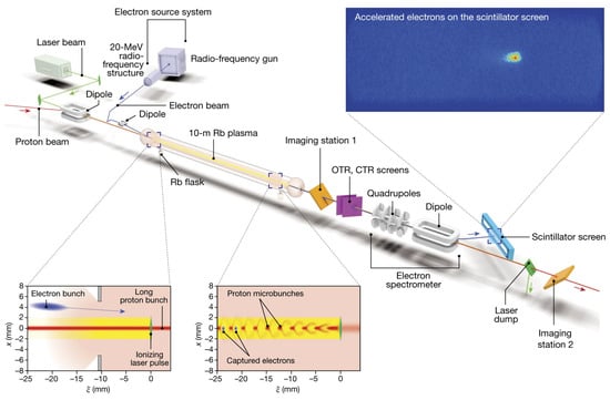
Figure 1.
Schematic of the AWAKE Run 1 (2016–18) layout. The laser and proton beams are merged before entering the plasma source. A beam of 10–20 MeV electrons is also merged with the beam line and injected into the entrance of the plasma source. The plasma source contains rubidium vapour at about 200 C with precise temperature control over the full 10 m. The beams exit the plasma source and a series of diagnostics are used to characterise them. There are two imaging stations to measure the transverse profile of the proton bunch and screens emitting optical and coherent transition radiation (OTR and CTR) to measure the longitudinal profile of the proton bunch. Electrons are separated from the protons using a dipole magnet which also induces an energy-dependent spread which is measured on a scintillator screen, imaged by a camera. Diagrams of the proton bunch self-modulation and electron capture are shown in the bottom left. A typical image of the accelerated electron bunch as observed on the scintillator screen is shown in the top right.
The proton bunch propagates in a plasma created by a relativistic ionisation front (RIF). The RIF is the result of the propagation of a short and intense laser pulse in a rubidium vapour [25,26,27,28]. When the RIF is placed within the proton bunch, the part of the bunch behind the RIF travelling in plasma is transformed into a train of microbunches. This is shown in Figure 2a where a clear periodic charge density structure at ps is observed.
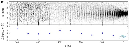
Figure 2.
(a) Time-resolved image of the SM proton bunch with the RIF placed 125 ps (0.5, where is the RMS duration of the proton bunch) ahead of bunch centre (front of the bunch at ps), and plasma electron density 10 cm (other parameters in [29]). The RIF is at ps on the image. (b) Relative RMS phase variation of the modulated bunches (in % of 2 or of a modulation period) for each set of images acquired every 50 ps along the bunch and aligned in time using a reference laser pulse signal visible as a vertical line at the bottom of image (a) ( mm). From Ref. [29].
The front ( ps on Figure 2a) is unaffected. The period of the train or the modulation frequency is determined by the plasma electron frequency, [30], measured over one order of magnitude in plasma electron density : (the electron plasma frequency in a plasma with electron density is: , , where e is the elementary electric charge, is the permittivity of free space and is the electron mass.). The train formation is a transverse process; protons between microbunches leave the bunch axis and form an expanding halo. The halo radius measured 10 m downstream from the plasma exit indicates that protons gained radial momentum from transverse wakefields with amplitudes reaching hundreds of MV/m [31]. This amplitude exceeds their initial amplitude driven at the RIF at the plasma entrance (<10 MV/m). This indicates that wakefields grow along the plasma, whereas the increase in radius reached by halo protons along the bunch shows that they also grow along the bunch, with both growths expected [21]. Correspondingly, large longitudinal wakefields lead to a 2 GeV energy gain of externally injected 19 MeV test electrons [24,32]. Acceleration experiments also suggest that wakefields may break in the back of the bunch, due to the large amplitude of the wakefields and to the finite radial extent of the plasma [33,34]. Combined halo radius and acceleration results in experiment and simulations show that the SM process saturates a distance between three and five metres along the plasma [35].
Numerical simulation results suggest that injection and acceleration of electrons are ineffective during the SM growth. If the electrons are injected along the proton beam axis, they are defocused in the region of longitudinally varying plasma density near the entrance to the plasma section [21,36,37]. If the electrons are injected at a small angle, they cross the transverse boundary of the plasma column which reflects or scatters most of the injected charge [38]. This is the likely reason why the measured accelerated charge [24,35] is significantly smaller than that simulated without the effect of boundary crossing [21].
The phase velocity of the wakefields during SM is less than the speed of light c [18,19], which prevents electrons from being accelerated to high energies [39]. This also causes microbunch destruction at late stages of SM development [40,41]. Fortunately, the phase velocity of the wakefields can be influenced by plasma density gradients along the beam trajectory [21]. It also changes the number of protons remaining in the microbunches and the length of the train: more charge and a longer train with positive density gradients, as demonstrated experimentally [42] and detailed in simulations [43].
Experimental and simulation results also reveal that with a density gradient the modulation frequency is not unique and varies radially across the time-resolved charge distribution of the train and halo observed 3.5 m from the exit of the plasma [43]. The structure of the distribution confirms that protons forming the halo left the wakefields over the first few metres of plasma, their distribution carrying the plasma frequency near the plasma entrance. The microbunch train, having travelled through the entire plasma, carries the frequency at the end of the plasma. We observe this with negative, linear density gradients [42] with which we also observe the largest frequency variations, with shorter trains, better able to adjust their modulation frequency to the local plasma frequency.
The reproducibility of the accelerating structure in the plasma is essential for the controlled acceleration of an externally-injected electron bunch. The electron bunch must be placed at the proper phase within the wakefields. That is, at a position within the train where wakefields have reached their maximum, and more precisely, within a fraction of a period of the wakefields, where fields are accelerating and focusing. The precise location is determined, for example, by loading of the wakefields for minimisation of energy spread and for emittance preservation [44]. While we do not measure the reproducibility of the wakefields from event to event, we demonstrated that when the RIF provides initial wakefields with sufficient amplitude, the phase of the bunch modulation with respect to the RIF is reproducible, despite variation of the incoming bunch parameters [29]. That is, the SM process is seeded, i.e., reproducible and driven away from its instability (SMI) regime [17]. In this seeded mode, we measure RMS variations of the modulation phase smaller than 8% of a modulation period (Figure 2b) all along the bunch train. We observe the instability when the RIF is placed further than ahead of the centre of the bunch with RMS duration (typically ps). When we place the RIF ahead of the centre of the bunch, the bunch propagates in a pre-formed plasma whose density is decaying in time because of radial expansion and recombination. Recording the modulation frequency as a function of RIF timing provides a measurement of plasma density as a function of time after ionisation [45].
While the SM process is the lowest-order, symmetric mode of interaction between the long incoming bunch and the plasma, signs of the non-axi-symmetric mode, the hose instability [46,47], were also observed. However, this mode was only observed at low plasma densities, , much lower than those that led to significant energy gain, .
The above results, in particular the occurrence and the saturation of the SM process of the 400 GeV proton bunch over a distance less than 10 m of plasma, with its phase reproducibility, the possibility to accelerate electrons in the wakefields, the absence of hosing instability and the generally excellent agreement between experimental and simulation results [33,35,43,48], allow for the planning of the next experiments [49]. These will be conducted in a number of steps geared towards experiments with two plasmas aimed at producing a multi-GeV electron bunch with charge, emittance and relative energy spread sufficient for the applications described in this manuscript.
3. The AWAKE Run 2 Physics Programme
The Run 2 physics programme is driven mostly by the long-term goals presented in this paper: producing a high-energy electron bunch with quality sufficient for high-energy or particle physics applications. Run 2 will again use proton bunches from the SPS. The main difference with Run 1 is the use of two plasma sources, one for SM and one for acceleration, thereby allowing for on-axis injection of the electron bunch into the accelerator plasma and for better control of parameters [50].
The first part of Run 2 focuses on the self-modulator, i.e., on the generation of the self-modulated proton bunch to drive the accelerator. The second part of Run 2 focuses on the accelerator, i.e., on external injection of the electron bunch and on scaling of its energy gain to higher energies.
We determined in Run 1 that, as predicted by numerical simulations [21,51], the SM process saturates over a distance of 3–5 m [35]. Experiments with two plasmas will thus include a 10 m long self-modulator plasma, followed by a 10 m long accelerator plasma. In the current plan, the two plasma sources will be based on laser ionisation of a Rb vapour [25]. These are the only sources known so far that provide a plasma density step in the self-modulator [52] and the desired density uniformity [53] in the accelerator.
3.1. Self-Modulator
The self-modulator will have two new features: the ability of seeding the SM process using an electron bunch and the ability of imposing a plasma density step. These two features will be first tested independently, and then together.
3.1.1. Electron-Bunch Seeding
A major result of Run 1 was the demonstration of the seeding of the SM process using a RIF [30]. However, this seeding method leaves the front of the bunch, ahead of the RIF, un-modulated. Since AWAKE long-term plans call for an accelerator plasma tens to hundreds of metres long, this plasma will have to be pre-formed. The laser ionisation process of Run 1 does not scale to such long plasma because of energy depletion of the laser pulse and because of the focusing geometry. In this preformed plasma, the un-modulated front of the bunch could experience SMI in the accelerator plasma. The wakefields driven by this front SMI could interfere with the self-modulated back of the bunch and with the acceleration process.
The SM process can also in principle be seeded by a preceding driver of wakefields, such as an electron bunch or a laser pulse. In this case, the entire proton bunch becomes self-modulated and the possible issue with the un-modulated front would be avoided.
The programme thus consists of demonstrating that the SM process can indeed be seeded by the electron bunch available in the Run 1 experimental setup. The method to be used is similar as that of Run 1 [29], i.e., determining the timing of microbunches appearing along the bunch with respect to the time of the electron bunch, after 10 m of plasma.
3.1.2. Plasma Density Step
Numerical simulation results suggest that in a plasma with constant density along the beam path, the continuous evolution of the bunch train and wakefields leads to a decay of the amplitude of wakefields after their saturation [40,41]. These results also suggest that when applying a density step, some distance into the plasma, within the growth of the SM process, wakefields maintain a near-saturation amplitude for a long distance along the plasma. Figure 3 illustrates how the density step changes the wakefield amplitude in the SM and acceleration plasma sections. These simulations are performed in the axi-symmetric geometry with the quasi-static code LCODE [54,55]. The parameters of the density step were optimised for the strongest wakefield at m with no gap between the sections [56]. The density step is seen to strongly increase the wakefield at the acceleration stage even in the presence of a 1 m gap.
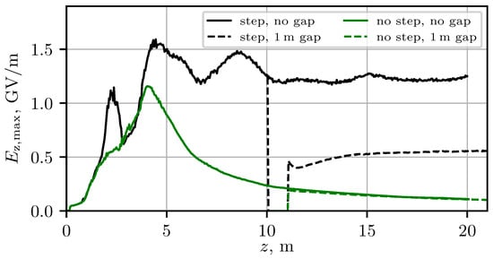
Figure 3.
The amplitude of the excited wakefield in the uniform plasma and in plasma with the optimised density step with and without a 1 m gap between SM and acceleration plasma sections. The SM process is seeded by an electron bunch. The density step is the linear growth of the plasma density from to at the interval between m and m.
The AWAKE plasma source is based on a rubidium vapour, along which a uniform temperature is imposed to obtain a correspondingly uniform vapour density. Laser-pulse ionisation then turns this uniform vapour density into an equally uniform plasma density [30]. One can therefore simply impose a temperature step along the column to obtain the corresponding plasma density step [52]. Measurements of the effect of the plasma density step on the amplitude of the wakefields will include effects of the size and shape of the bunch halo formed by defocused protons, measurements of plasma light signals, and measurements of electron acceleration.
3.2. Accelerator
The length of the accelerator plasma is 10 m for the first experiments. This is much longer than the distance it takes for the amplitude of wakefields to settle to steady values after the injection point (see Figure 3). This distance is ∼2 m and results from the transverse evolution of the proton bunch in the vacuum gap between the two plasmas. The plasma is thus long enough for the expected energy gain to be in the multi-GeV range along the ensuing length of plasma where the driving of the wakefields is stationary.
3.2.1. External Injection
In Run 1, acceleration was obtained with an off-axis injection geometry [21]. This geometry was chosen to avoid defocusing of the injected electrons in the density ramp located at the entrance of the plasma [36,37]. In this region, the yet un-modulated proton bunch drives transverse fields which are focusing for its own positive-charge sign, but defocusing for injected electrons. A scheme that avoids these issues is to inject electrons on axis after the SM process has saturated. The parameters of the electron bunch must be such that it reaches high energies, low final relative energy spread and preserves its incoming emittance. The SM process does not lead to blow-out of plasma electrons from the accelerating structure because the resonant wave drive stops when the plasma wave becomes nonlinear and its period elongates [57]. The initial electron bunch density must therefore exceed the plasma electron density: to reach blow-out. Blow-out of plasma electrons is necessary for the focusing force of the plasma to become that of the pure ion column, with strength increasing linearly with radius [58]. The normalised emittance and focus RMS size of the electron bunch at the plasma entrance must be adjusted to satisfy matching to the ion column focusing force:
For typical parameters ( mm mrad, ), electrons must have a large enough energy or relativistic factor to be focused to the small transverse size (m, ). In addition, the bunch length and timing in the wakefields must be optimised to load wakefields to minimise the final relative energy spread .
An example set of parameters was developed using a toy-model for the proton bunch [44]. This example shows that with parameters satisfying the above conditions, about 70% of the initial 100 pC bunch charge preserve their emittance and reach 1.67 GeV/c over 4 m of plasma with (core).
3.2.2. Scalable Plasma Sources
Assuming the success of experiments on electron injection into the wakefields of a 10 m long plasma, energy gain suitable for applications can in principle be achieved by extending the length of the accelerator plasma. However, the distance over which laser ionisation can occur is limited by depletion of the energy of the laser pulse and by the focusing geometry. We are therefore developing other plasma sources that do not suffer from length limitations: direct-current electrical discharge in noble gases [59] and helicon argon plasma [60].
The direct-current discharge plasma source (DPS) uses a short pulse (∼s) high-current pulse (∼kA) through the length of a glass tube, filled with a high atomic number noble gas at low pressure (∼10 Pa) [59]. This follows a fast-rising high-voltage pulse (50–100 kV) able to ignite long tubes ( m) into uniform plasma densities. We are currently developing a 10 m long plasma source consisting of a double discharge from a mid length common cathode to two anodes in the extremities. Operation at the plasma densities relevant for AWAKE has been demonstrated. We are currently engaged in demonstrating the ability of the plasma source to reach the required plasma density uniformity. With this source, the length scalability can potentially be reached by stacking together multiple plasma sections (with lengths of a few metres to a few tens of metres) using common cathodes and anodes.
Helicon plasma belong to the class of magnetised wave heated plasmas [61]. They consist of a dielectric vacuum vessel and an external wave excitation antenna, which is powered by radio frequencies. The excited helicon waves heat the plasma and have been demonstrated to generate discharges with high plasma densities [62]. Its length can thus in principle be extended over long lengths by stacking cells. Measurements show that the plasma density typical of AWAKE () can be reached [60]. The challenge is to demonstrate that the required plasma density uniformity can also be reached. This demonstration requires highly accurate and localised plasma density measurements. Specific diagnostics such as Thomson scattering [63] and optical emission spectroscopy are being developed.
4. Overview of AWAKE Run 2 Setup
The AWAKE Run 2 scheme including the two plasma sources, i.e., a self-modulator and an accelerator, and a new electron beam system is shown in Figure 4.
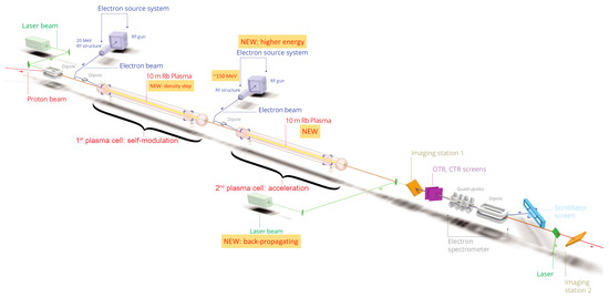
Figure 4.
Layout of AWAKE Run 2.
The AWAKE Run 2 programme is subdivided into four phases Run 2a, 2b, 2c and 2d, following the physics programme described above.
The current AWAKE experiment is installed upstream of the previous CERN neutrinos to Gran Sasso (CNGS) facility [64]. The ∼100 m long CNGS target cavern, which currently houses the CNGS target and secondary beam line while their activation levels decay, is separated from the AWAKE experiment by a shielding wall.
Phases Run 2a and Run 2b will be carried out in the existing AWAKE facility, having started in 2021 and are foreseen to continue until 2024. For Run 2c and Run 2d, however, the CNGS target area needs to be dismantled; around three years are required for the removal of the CNGS target area and the installation and commissioning of the additional equipment for AWAKE Run 2c, where AWAKE takes advantage of the general 1–2 years shutdown period of the CERN injector complex in 2026/27. It is planned to start AWAKE Run 2c with first protons after LS3 in 2028.
4.1. AWAKE Run 2a
The Run 2a experiments, focusing on electron bunch seeding of the SM process, use the same infrastructure as that of AWAKE Run 1; bunches of protons are extracted from the CERN SPS and each consists of protons, each with energy 400 GeV. The bunch length can be adjusted between 6 and 12 cm and the bunch is focused at the plasma entrance to a transverse RMS size of mm. The plasma is 10 m long, has a radius of approximately 1 mm and a density uniformity better than 0.1% [26]. To create the plasma, rubidium is evaporated in a heat exchanger and the outermost electron of each rubidium atom is ionised with a laser pulse with a pulse length of 120 fs and a pulse energy of ≤450 mJ. The vapour (and thus also the plasma) density is controlled by the temperature of the source and is adjustable between 0.5 and 10 atoms/cm.
In AWAKE Run 1, the relativistic ionisation front of the laser was also used to seed the self-modulation process by placing it close to the centre of the proton bunch. In AWAKE Run 2a the laser pulse is placed in front of the proton bunch so that the entire proton bunch interacts with plasma.
In AWAKE Run 1, electron acceleration in the proton-driven plasma wakefield was demonstrated with externally injected 10–20 MeV electrons [24]. These 100–600 pC electron bunches have a duration of ps and are produced in a RF photo injector based on an S-band structure. In AWAKE Run 2a, these electrons are used to seed the proton bunch SM.
4.2. AWAKE Run 2b
In the Run 2b experiments, the effect of the plasma density step on the SM process will be measured. This requires a new vapour source and corresponding new diagnostics. The new vapour source is in its design phase and will be exchanged with the current source for Run 2b. It includes additional observation ports in order to diagnose the electron plasma density that sustains wakefields. The experimental programme will focus on direct measurements of the plasma wakefields. To this end, different diagnostics are currently being evaluated (e.g., THz shadowgraphy diagnostics and plasma light diagnostics).
4.3. AWAKE Run 2c
The CNGS cavern needs to be emptied in order to house the baseline AWAKE Run 2c and Run 2d experiments, which includes the second electron source, beam line, klystron system and the second vapour source.
In order to be able to integrate the entire Run 2c experiment in the AWAKE facility, the first plasma cell will be shifted by around 40 m downstream of its current location and consequently the new equipment will also be accordingly moved downstream. This change also needs some downstream shifting of the proton beam line final dipole magnets; however, despite challenging aperture constraints, no extra magnets are required. The second electron source needs to deliver electrons with 150 MeV energy, bunch charge of a few 100 pC, beam emittance of 2 mm mrad and a short bunch length of 200 fs duration. The baseline proposal is a novel RF gun and two X-band structures for velocity bunching and acceleration. A prototype system is currently being developed in order to demonstrate the required beam parameters for AWAKE and to study the mechanical and integration aspects in the AWAKE facility.
The beam line design for the new 150 MeV electron beam from the electron source to the plasma source is very challenging, given the tight beam specifications [65]: the beam must be matched to the plasma at the plasma merging point, with a RMS beam size satisfying , zero dispersion and , for emittance, , and Twiss parameter, , where 0.00487 is the required function in metres. In addition, the gap between the two vapour sources must be as short as possible [66], i.e., ≤1 m. Additionally considering integration limits from the width of the tunnel, the baseline proposal of the electron transfer line is a dogleg design. Studies on the injection tolerances of the proton and electron beam are currently ongoing and are key to controlled plasma wakefield acceleration.
The accelerator plasma source will have a length of about 10 m and will be based on the laser ionised Rb vapour source (as used in AWAKE Run 1 and in the first vapour source). The laser beam for the ionisation in the second vapour source will be injected from its downstream end, counter-propagating to the proton beam. Although the same laser as for the first vapour source can be used in Run 2c by splitting its output beam on two branches, additional laser transport lines and a compressor chamber need to be integrated.
4.4. AWAKE Run 2d
Once Run 2c has demonstrated electron acceleration to high energies while controlling beam quality, the second plasma source can be exchanged with a different plasma technology. These sources will be scalable to long distances in order to accelerate electrons to energies of several 10s of GeV and beyond, allowing for the first particle physics applications.
As discussed in the previous section, the plasma technologies currently under study at CERN are helicon plasma sources and discharge plasma sources.
With the CNGS target cavern fully dismantled, there is enough space available to install a plasma source of 10s of metres in length. Therefore infrastructure changes for Run 2d concern mainly the different services such as powering, cooling, etc. needed for the plasma source.
First studies also show that enough space is available for a prototype fixed-target experimental setup, allowing the first particle physics experiments to be conducted with electrons accelerated from AWAKE.
5. Particle Physics Applications of AWAKE
As outlined in the previous sections, the AWAKE scheme aims to develop an acceleration technology that can be used to provide beams for particle physics experiments. The ultimate goal for novel acceleration schemes is to provide the technology for a high energy, high luminosity, linear electron–positron collider with centre-of-mass energies and luminosities cm s. In principle, though, any experiment that requires a source of bunched high energy electrons could utilise the AWAKE scheme. Initial application focuses on experiments with less challenging beam parameters than a linear collider, although still having a strong and novel particle physics case.
By the conclusion of Run 2, the AWAKE collaboration should have demonstrated acceleration of electrons with stable GV/m gradients. Scalable plasma sources should have been developed that can be extendable up to even kilometres in length. The acceleration process should preserve the beam quality resulting in bunches with transverse emittance of below 10 mm mrad. With these developments, using proton bunches from the SPS, acceleration of electrons to 10s of GeV, and even up to ∼200 GeV, should be possible [67]. Use of the LHC protons with energy 7 TeV would enable acceleration of electrons up to about 6 TeV [68]. A limitation of the current proton drivers is their repetition rate and hence the luminosity of any application of the AWAKE scheme. Given this, high energy applications are considered and also those where the luminosity is less critical.
The first ideas for particle physics experiments based on electron bunches from the AWAKE scheme were proposed in previous papers [69,70]. The applications are discussed below, along with extensions and new ideas that have been developed since. The first application would be to use a high energy electron beam impinging on a target in order to search for new phenomena related to dark matter, see Section 5.1. Another potential first application is collision of an electron bunch with a high-power laser pulse to investigate strong-field QED, see Section 5.2. Both of these experiments would require electrons of 10s of GeV, although higher energies could be considered. An electron–proton collider would be the potential first use of the AWAKE scheme for a high-energy collider. There is a physics case for such a collider with electrons of 10s of GeV, and up to the TeV scale, when in collision with protons from the LHC. Each has a strong particle physics case but with less strict demands on beam quality than an collider, see Section 5.3. Finally, a new development is consideration of the proton beam at Brookhaven National Laboratory (BNL) as the wakefield driver to develop a compact electron injector which is discussed in Section 5.4.
5.1. A Beam-Dump Experiment for Dark Photon Searches
Dark photons are postulated particles [71,72,73] which could provide the link to a dark or hidden sector of particles. This hidden sector could explain a number of issues in particle physics, not least of which is that they are candidates for dark matter which is expected to make up about 80% of known matter in the Universe. Dark photons are expected to have low masses (sub-GeV) [74,75] and couple only weakly to Standard Model particles and so would have not been seen in previous experiments. The dark photon, labelled , is a light vector boson which results from a spontaneously broken new gauge symmetry and kinetically mixes with the photon and couples to the electromagnetic current with strength .
A common approach to search for dark photons is through the interaction of an electron with a target in which the dark photon is produced and subsequently decays. Many experiments, current and proposed [76], are searching for dark photons and other feebly interacting particles using electrons impinging on a target. The initial electron beam energy varies, although only the NA64 experiment at CERN [77,78,79] has access to high energy electrons ()) with other experiments limited to below ()). A limitation of experiments is the rate of electrons on target which in the case of NA64 is about electrons on target per second as they are produced in secondary interactions of the SPS proton beam. Given the limitations of the number of electrons on target for a high energy beam, the AWAKE acceleration scheme could enable an experiment to extend the search for dark photons as the number of electrons is expected to be several orders of magnitude higher. Assuming [80] a bunch of electrons, each of 50 GeV in energy, and a running period of 3 months gives electrons on a target of centimetre transverse size. As the AWAKE scheme produces bunches of electrons, an experiment based on this will run as a beam-dump experiment in which electrons are absorbed in a target and a search for dark photons decaying to an pair is performed. This is in contrast to other fixed-target experiments in which single electrons impact on a target and other decay channels can be searched for such as dark photons decaying to a pair of dark matter particles which do not leave deposits in the detectors and so have a signal of missing energy.
The potential production of dark photons is sensitive to the experimental setup. Using initial electrons of 50 GeV, an experimental setup, as shown in Figure 5, has been simulated using GEANT4 [81,82,83]. To characterise the performance of the experiment, the sensitivity to the coupling strength, , and mass, , is considered and usually represented in a plot of the two. Examples are shown in Figure 6 in which the sensitivity is shown for the number of electrons on target and the thickness of the target. These results show the value of having as many electrons on target where the sensitivity to both and is increased with an increasing number of electrons. They also show that the sensitivity is reduced with increasing target thickness; however, having a thicker target is necessary in order to keep the background rate under control.
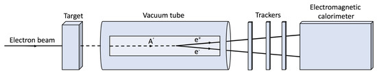
Figure 5.
Schematic layout of an experiment to search for dark photons. In the AWAKE scheme, a bunch of electrons enters from the left and impacts on a target of in length. A produced dark photon travels through a vacuum tube of length in which it decays to an pair which are then measured in a detector system such as a tracking detector and calorimeter.
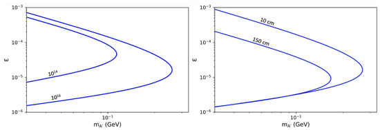
Figure 6.
Sensitivity to dark photon production shown for the coupling strength, , and mass, . The varied parameters of the proposed beam-dump experiment are (left) the number of electrons on target and (right) the thickness of the solid metal target which the electrons hit. The initial electron energy is assumed to be 50 GeV.
Expected sensitivities to dark photons in an experiment using an electron beam from the AWAKE scheme are shown in Figure 7 in comparison with previous, current and proposed experiments [84]. Limits from previous experiments are shown as grey-shaded areas in the plane. Expected sensitivities from current and future experiments are shown as coloured lines. Using electrons of energy 50 GeV will allow dark photon searches to be extended towards higher masses in the range of couplings, . As there is the possibility of producing much higher energy electron beams, at the TeV scale, with the AWAKE scheme using the LHC protons as the wakefield driver, the sensitivity is shown for 1 TeV electrons; such an experiment could run as part of a future collider facility, such as the very high energy electron–proton (VHEeP) collider [85], after collisions, and as the beam is dumped. The sensitivity is extended to much higher mass values as well as lower . The mass values reached approach 1 GeV, far beyond the capability of any other experiment, current or planned.
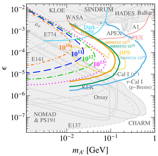
Figure 7.
Limits on dark photon production decaying to an pair in terms of the mixing strength, , and dark photon mass, , from previous measurements (light grey shading). The expected sensitivity for the NA64 experiment is shown for a range of electrons on target, –. Expectations from other potential experiments are shown as coloured lines. Expected limits are also shown for (orange line) or (green line) electrons of 50 GeV (“AWAKE50”) on target and (blue line) electrons of 1 TeV (“AWAKE1k”) on target provided to an experiment using the future AWAKE accelerator scheme. From Ref. [84].
Depending on the future running of the SPS accelerator which feeds the AWAKE experiment, a larger area of parameter space could be investigated if more electrons on target were to be possible. In addition, recent investigations indicate that higher energy electrons, up to about 200 GeV, are possible [67] using the SPS protons as the drive beam which would also extend the sensitivity beyond that shown in Figure 7 for 50 GeV electrons. Additionally, other decay channels, such as or could also be considered and the experiment optimised to be sensitive to these additional channels.
5.2. Investigation of Strong-Field QED in Electron–Laser Collisions
Progress in high-power laser technology has revived the study of strong-field quantum electrodynamics (QED) since the pioneering experiment, E144 [86], that investigated this area of physics in electron–laser collisions in the 1990s. As electrons pass through the intense laser pulse and so experience strong fields (the higher the intensity, the stronger the fields), QED becomes non-linear and experiments mimic the conditions that occur on the surface of neutron stars, at a black hole’s event horizon or in atomic physics.
The E144 experiment at SLAC investigated electron–laser collisions with bunches of electrons, each of energy ∼50 GeV. Experiments (E320 at SLAC and LUXE at DESY with the European XFEL) are underway or planned with high-quality electron bunches, with energies in the 10–20 GeV range [87,88]. Given the expectation of bunches of electrons, each of energies in the 10s of GeV range, from the AWAKE scheme, experiments investigating strong-field QED are an obvious initial application with the possibility to also have higher electron energies. As the rate of electron–laser collisions is limited by the roughly 1 Hz repetition frequency of high-power lasers, high-rate electron bunches are not required.
5.3. High Energy Electron–Proton/Ion Colliders
The HERA accelerator complex in DESY, Hamburg, has so far provided the only electron–proton collider. With electrons and protons at maximal energies of 27.5 GeV and 920 GeV, respectively, a centre-of-mass energy of about 318 GeV was achieved. An electron–ion collider (EIC) [89] is to start operation in BNL in about a decade with lower centre-of-mass energy than HERA, up to about 140 GeV. However, it will have significantly higher luminosity, highly polarised beams and variation in the centre of mass energy and ion species, providing a rich physics programme through its great flexibility. A higher energy electron–proton collider, LHeC (large hadron–electron collider) [90,91], has been proposed using electrons of 50 GeV in collision with LHC protons so yielding centre-of-mass energies just above the TeV scale. The possibility of an LHeC-like collider based on the AWAKE scheme to produce 50 GeV electrons is outlined here. A significantly more compact design should be possible, although with a much reduced luminosity performance. Even more compelling is the possibility of using the AWAKE scheme to provide TeV electrons and so have electron–proton collisions at centre-of-mass energies of 9 TeV [85] and this is briefly summarised. Electrons at 3 TeV could also be used in fixed-target mode and provide a centre-of-mass energy of ∼80 GeV, thereby achieving similar values to the EIC.
A high energy collider could be the first collider application of the AWAKE scheme. In comparison to a high energy collider, an collider poses fewer challenges to the AWAKE scheme as only one beam is required, such low emittances are not needed (as the proton emittance dominates) and potentially positrons are not needed, although they are desirable. Given the possibility of providing electrons using the SPS protons to drive wakefields, this was formulated in the PEPIC (plasma electron–proton/ion collider) project. The electrons would collide with protons from the LHC and using their expected parameters during the high-luminosity phase, this would lead to an instantaneous luminosity of , where parameters expected from a future AWAKE facility have been assumed for the electron bunches [80]. So although PEPIC has the same energy reach (and possibly even beyond) as the LHeC, it would have a luminosity many orders of magnitude lower. Such a low luminosity will not allow investigation of the Higgs sector, detailed measurements of electroweak physics or other phenomena that occur at high , where in the virtuality of the photon emitted by the electron in the collision. However, processes that occur at low x, where x is the fraction of the proton’s momentum carried by the struck parton, have very high cross sections and so even with a low luminosity, large event samples will be produced. The focus of the physics programme would then be on understanding the structure of matter and quantum chromodynamics (QCD), the theory of the strong force, in a new kinematic regime.
The PEPIC collider would be an option for CERN should the LHeC project not go ahead, where the initial study shows that it is possible, could be housed within the current CERN site, and has a novel particle physics programme. Schemes to increase the luminosity should be considered where the current design is mainly limited by the filling time of the SPS. Mechanisms to increase the SPS bunch repetition frequency would lead to a corresponding increase in luminosity and so should be studied, along with other parameters relevant for the luminosity such as the electron bunch population and proton bunch size. The possibility to accelerate electrons up to 200 GeV using the SPS protons as the drive beam would lead to a doubling of the centre-of-mass energy (2.4 TeV) and so an increased kinematic range. This provides a larger phase space to search for new physics and larger lever arm to investigate the energy dependence of high-energy cross sections.
Using the LHC protons to drive wakefields could lead to electrons at the TeV scale and so an collider with centre-of-mass energies . This has been formulated as the VHEeP collider [85] in which electrons at 3 TeV are collided with the LHC protons at 7 TeV giving a centre-of-mass energy of 9 TeV. This represents a factor of 30 increase compared to HERA and hence an extension in x and of a factor of 1000. As with PEPIC, the luminosity of VHEeP is relatively low, estimated [92] to be – or around 1 pb per year. This is mainly limited by the LHC protons needed to drive wakefields which will need to be dumped after this process and so protons will need to be refilled for the further acceleration of electrons by the AWAKE scheme. Schemes need to be considered such as squeezing the proton or electron bunches, having multiple interaction points, etc. that will increase the luminosity.
Even though the luminosity of the VHEeP collider is modest, the very high energy provides a compelling particle physics cases. At low values of , 10s of millions of events are expected and so high precision measurements and searches for new physics will be possible. This will allow investigation of hadronic cross sections and the structure of matter at very high energies. The collisions are also equivalent to a photon of energy of 20 PeV on a fixed target and so has synergy with cosmic-ray physics. Searches for physics beyond the Standard Model, such as quark substructure or leptoquarks, will also be possible. Even with modest luminosities, the very high energy ensures that the sensitivity to leptoquarks exceeds that possible in proton–proton collisions at the LHC. The particle physics case is discussed in more detail elsewhere [69,70,85]. As well as collisions which have been the focus so far, collisions should be considered.
5.4. Use of BNL Proton Beams for a Compact Electron Injector for a Future Electron–Ion Collider
The AWAKE acceleration scheme has been considered as a possible technology for the injector for the high energy electron beam for the future EIC. The EIC is expected to collide electrons of up to 20 GeV with protons of up to 275 GeV—a possible site at BNL in the US already has a circular, 4 km long proton accelerator, but will require a new electron accelerator of similar size. It has been proposed [93] to use the AWAKE technology at BNL by using their high-intensity proton bunches to generate large wakefields and hence accelerate electrons to high energies over short distances. Along with CERN, where AWAKE is currently based, BNL is one of the few places in the world with high energy proton bunches that can be used for the AWAKE acceleration scheme.
It has been assumed that the proton bunch parameters expected for the future EIC, namely a proton energy of 275 GeV, protons/bunch, a bunch length of 5 cm and a bunch radius of 40 or m. These are similar values to currently used at AWAKE using CERN’s SPS accelerator except that the smaller bunch size allows for a higher plasma density to be used which should yield larger accelerating fields. Using these parameters, the process has been simulated and the accelerating electric field determined for the two values of the bunch radius. The results are shown in Figure 8, where the larger beam radius is given by the red line and smaller beam radius by the blue line. In the more promising scenario, with a bunch radius of m, the peak field is almost 7 GV/m, which although falls rapidly, levels off above 1 GV/m, an accelerating gradient well above current conventional accelerator technology.
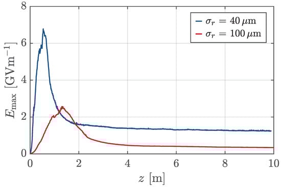
Figure 8.
Evolution of the peak longitudinal fields driven by the BNL proton drive beams over 10 m using bunch parameters which differ only in their transverse size, m or m. From Ref. [93].
This confirms that the high, >1 GV/m gradients, can be harnessed and that the required maximum energy for the EIC of 20 GeV could be achieved in under 20 m. There are indications that the accelerating gradient can be frozen [41] soon after the peak field, which will be studied at AWAKE (see Section 3.1.2 and Section 4.2), and values more like 5–6 GV/m would be observed in Figure 8 in which case electrons could be accelerated to the required 20 GeV in under 4 m. Alternatively, significantly higher electron energies than currently planned, of 50 GeV and beyond, could be achieved and so extend the kinematic reach in the investigation of parton dynamics in the proton at the EIC.
6. Summary
This article summarised the plans for AWAKE Run 2, which will take the scheme of proton-driven plasma wakefield acceleration from proof of concept to a technology which can provide beams for particle physics experiments.
The proof of concept, AWAKE Run 1, showed that a long proton bunch can be modulated into a series of microbunches, which are regularly and reproducibly spaced. These microbunches constructively interfere to generate strong electric fields in their wake. The wakefields were sampled by an externally-injected bunch of electrons which were accelerated from about 20 MeV up to about 2 GeV within 10 m of plasma, representing an average field of >200 MV/m, with peak fields of up to ∼1 GV/m expected.
In AWAKE Run 2, the proof of concept will be significantly extended to address the requirements needed to develop beams for use in particle physics experiments. The primary aims of AWAKE Run 2 are to sustain the expected peak fields of 0.5–1 GV/m over long distances, thereby increasing the accelerated electron energy; to demonstrate that the emittance of the electron bunch is preserved during acceleration in plasma; and to develop plasma sources that are scalable to 100s of metres and beyond. This will be achieved in a staged approach during the 2020s which will require significant extension to the current AWAKE facility, in particular the development of short witness electron bunches for injection, new plasma sources and a suite of diagnostics to measure the physics of the acceleration process.
After completion of AWAKE Run 2, at the end of the 2020s, the scheme should have been sufficiently demonstrated such that it can be used to provide beams for particle physics experiments. Given the challenge in producing high energy electron bunches by conventional means, electrons in the 20–200 GeV range, as driven by protons from the SPS, or even at the TeV scale if using LHC protons as the wakefield driver, can be used in a variety of particle physics experiments. Such electron bunches can be used in experiments to search for dark photons, to measure QED in strong fields or as the injector or main accelerator for the electron arm of an electron–proton or electron–ion collider. These first applications place less stringent requirements on the parameters of the electron bunch than for a high energy, high luminosity linear electron–positron collider, although they will provide a useful stepping stone, along with continued R&D, to such ultimate applications whilst also providing beams for novel particle physics experiments.
Author Contributions
E.G., K.L., P.M. and M.W. conceived, wrote and edited this article. Members of the AWAKE collaboration contributed to the review of the manuscript and to the work here summarised. All authors have read and agreed to the published version of the manuscript.
Funding
This work was supported in parts by a Leverhulme Trust Research Project Grant RPG-2017-143 and by STFC (AWAKE-UK, Cockcroft Institute core, John Adams Institute core, and UCL consolidated grants), United Kingdom; the Russian Science Foundation, project 20-12-00062, for Novosibirsk’s contribution; the National Research Foundation of Korea (Nos. NRF-2016R1A5A1013277 and NRF-2020R1A2C1010835); the Wolfgang Gentner Programme of the German Federal Ministry of Education and Research (grant no. 05E15CHA); M. Wing acknowledges the support of DESY, Hamburg. Support of the National Office for Research, Development and Innovation (NKFIH) under contract numbers 2019-2.1.6-NEMZ_KI-2019-00004 and MEC_R-140947, and the support of the Wigner Datacenter Cloud facility through the Awakelaser project is acknowledged. The work of V. Hafych has been supported by the European Union’s Framework Programme for Research and Innovation Horizon 2020 (2014–2020) under the Marie Sklodowska-Curie Grant Agreement No. 765710. TRIUMF contribution is supported by NSERC of Canada.
Data Availability Statement
No new data are provided in this article which presents a review of previous work.
Acknowledgments
The AWAKE collaboration acknowledge the SPS team for their excellent proton delivery.
Conflicts of Interest
The authors declare no conflict of interest.
Abbreviations
The following abbreviations are used in this manuscript:
| AWAKE | Advanced wakefield experiment |
| BNL | Brookhaven National Laboratory |
| CERN | European Organisation for Nuclear Research |
| (Conseil Européen pour la Recherche Nucléaire) | |
| CNGS | CERN neutrinos to Gran Sasso |
| DESY | Deutsches Elektronen-Synchrotron |
| EIC | Electron–ion collider |
| GEANT | Geometry and tracking |
| HERA | Hadron–electron ring accelerator |
| LHC | Large hadron collider |
| LHeC | Large hadron–electron collider |
| LUXE | Laser und XFEL experiment |
| PEPIC | Plasma electron–proton/ion collider |
| QCD | Quantum chromodynamics |
| QED | Quantum electrodynamics |
| RIF | Relativistic ionisation front |
| RMS | Root mean square |
| SLAC | Stanford Linear Accelerator |
| SM | Self-modulation |
| SMI | Self-modulation instability |
| SPS | Super proton synchrotron |
| VHEeP | Very high energy electron–proton |
| XFEL | X-ray free electron laser |
References
- Tajima, T.; Dawson, J.M. Laser electron accelerator. Phys. Rev. Lett. 1979, 43, 267. [Google Scholar] [CrossRef]
- Chen, P.; Dawson, J.M.; Huff, R.W.; Katsouleas, T.W. Acceleration of electrons by the interaction of a bunched electron beam with a plasma. Phys. Rev. Lett. 1985, 54, 693, Erratum in Phys. Rev. Lett. 1985, 55, 1537. [Google Scholar] [CrossRef] [PubMed]
- Joshi, C. The development of laser- and beam-driven plasma accelerators as an experimental field. Phys. Plasmas 2007, 14, 055501. [Google Scholar] [CrossRef]
- Esarey, E.; Schroeder, C.B.; Leemans, W.P. Physics of laser-driven plasma-based electron accelerators. Rev. Mod. Phys. 2009, 81, 1229. [Google Scholar] [CrossRef]
- Hogan, M.J. Electron and positron beam-driven plasma acceleration. Rev. Accel. Sci. Technol. 2016, 9, 63. [Google Scholar] [CrossRef]
- Albert, F.; Couprie, M.E.; Debus, A.; Downer, M.C.; Faure, J.; Flacco, A.; Gizzi, L.A.; Grismayer, T.; Huebl, A.; Joshi, C. 2020 roadmap on plasma accelerators. New J. Phys. 2021, 23, 031101. [Google Scholar] [CrossRef]
- Modena, A.; Najmudin, Z.; Dangor, A.E.; Clayton, C.E.; Marsh, K.A.; Joshi, C.; Malka, V.; Darrow, C.B.; Danson, C.; Neely, D.; et al. Electron acceleration from the breaking of relativistic plasma waves. Nature 1995, 377, 606. [Google Scholar] [CrossRef]
- Mangles, S.P.D.; Murphy, C.D.; Najmudin, Z.; Thomas, A.G.R.; Collier, J.L.; Dangor, A.E.; Divall, E.J.; Foster, P.S.; Gallacher, J.G.; Hooker, C.J.; et al. Monoenergetic beams of relativistic electrons from intense laser–plasma interactions. Nature 2004, 431, 535. [Google Scholar] [CrossRef] [PubMed]
- Geddes, C.G.R.; Toth, C.; Tilborg, J.V.; Esarey, E.; Schroeder, C.B.; Bruhwiler, D.; Nieter, C.; Cary, J.; Leemans, W.P. High-quality electron beams from a laser wakefield accelerator using plasma-channel guiding. Nature 2004, 431, 538. [Google Scholar] [CrossRef] [PubMed]
- Faure, J.; Glinec, Y.; Pukhov, A.; Kiselev, S.; Gordienko, S.; Lefebvre, E.; Rousseau, J.P.; Burgy, F.; Malka, V. A laser–plasma accelerator producing monoenergetic electron beams. Nature 2004, 431, 541. [Google Scholar] [CrossRef] [PubMed]
- Gonsalves, A.J.; Nakamura, K.; Daniels, J.; Benedetti, C.; Pieronek, C.; Raadt, T.C.H.; Steinke, S.; Bin, J.H.; Bulanov, S.S.; Tilborg, J. Petawatt Laser Guiding and Electron Beam Acceleration to 8 GeV in a Laser-Heated Capillary Discharge Waveguide. Phys. Rev. Lett. 2019, 122, 084801. [Google Scholar] [CrossRef]
- Blumenfeld, I.; Christopher, C.; Fran, D.; Mark, H.; Rasmus, I.; Richard, I.; Chandrashekhar, J.; Thomas, K.; Neil, K. Energy doubling of 42 GeV electrons in a metre-scale plasma wakefield accelerator. Nature 2007, 445, 741. [Google Scholar] [CrossRef] [PubMed]
- Litos, M.; Adli, E.; An, W.; Clarke, C.I.; Clayton, C.E.; Corde, S.; Delahaye, J.P.; England, R.J.; Fisher, A.S.; Frederico, J.; et al. High-efficiency acceleration of an electron beam in a plasma wakefield accelerator. Nature 2014, 515, 92. [Google Scholar] [CrossRef]
- Litos, M.; Adli, E.; An, W.; Clarke, C.I.; Clayton, C.E.; Corde, S.; Delahaye, J.P.; England, R.J.; Fisher, A.S.; Frederico, J.; et al. 9 GeV energy gain in a beam-driven plasma wakefield accelerator. Plasma Phys. Control. Fusion 2016, 58, 034017. [Google Scholar] [CrossRef]
- Schroeder, C.B.; Esarey, E.; Geddes, C.G.R.; Benedetti, C.; Leemans, W.P. Physics considerations for laser–plasma linear colliders. Phys. Rev. ST Accel. Beams 2010, 13, 101301. [Google Scholar] [CrossRef]
- Caldwell, A.; Konstantin, L.; Alexander, P.; Frank, S. Proton-driven plasma-wakefield acceleration. Nat. Phys. 2009, 5, 363. [Google Scholar] [CrossRef]
- Kumar, N.; Pukhov, A.; Lotov, K. Self-modulation instability of a long proton bunch in plasmas. Phys. Rev. Lett. 2010, 104, 255003. [Google Scholar] [CrossRef] [PubMed]
- Schroeder, C.B.; Benedetti, C.; Esarey, E.; Grüner, F.J.; Leemans, W.P. Growth and phase velocity of self-modulated beam-driven plasma waves. Phys. Rev. Lett. 2011, 107, 145002. [Google Scholar] [CrossRef] [PubMed]
- Pukhov, A.; Kumar, N.; Tückmantel, T.; Upadhyay, A.; Lotov, K.; Muggli, P.; Khudik, V.; Siemon, C.; Shvets, G. Phase velocity and particle injection in a self-modulated proton-driven plasma wakefield accelerator. Phys. Rev. Lett. 2011, 107, 145003. [Google Scholar] [CrossRef] [PubMed]
- Assmann, R.; Bingham, R.; Bohl, T.; Bracco, C.; Buttenschön, B.; Butterworth, A.; Caldwell, A.; Chattopadhyay, S.; Cipiccia, S.; Feldbaumer, E. AWAKE Coll., Proton-driven plasma wakefield acceleration: A path to the future of high-energy particle physics. Plasma Phys. Control. Fusion 2014, 56, 084013. [Google Scholar] [CrossRef]
- Caldwell, A.; Adli, E.; Amorim, L.; Apsimon, R.; Argyropoulos, T.; Assmann, R.; Assmann, R.; Bachmann, A.M.; Batsch, F.; Bauche, J.; et al. AWAKE Coll., Path to AWAKE: Evolution of the concept. Nucl. Instrum. Meth. A 2016, 829, 3. [Google Scholar] [CrossRef]
- Gschwendtner, E.; Adli, E.; Amorim, L.; Apsimon, R.; Assmann, R.; Bachmann, A.M.; Batsch, F.; Bauche, J.; Berglyd, V.K.; Marin, M.; et al. AWAKE Coll., AWAKE, the advanced proton driven plasma wakefield acceleration experiment at CERN. Nucl. Instrum. Meth. A 2016, 829, 76. [Google Scholar] [CrossRef]
- Muggli, P.; Adli, E.; Apsimon, R.; Asmus, F.; Baartman, R.; Bachmann, A.M.; Marin, M.; Batsch, F.; Bauche, J.; Olsen, V.K.; et al. AWAKE Coll., AWAKE readiness for the study of the seeded self-modulation of a 400 GeV proton bunch. Plasma Phys. Control. Fusion 2018, 60, 014046. [Google Scholar] [CrossRef]
- Adli, E.; Ahuja, A.; Apsimon, O.; Apsimon, R.; Bachmann, A.M.; Barrientos, D.; Batsch, F.; Bauche, J.; Olsen, V.K.; Bernardini, M.; et al. AWAKE Coll., Acceleration of electrons in the plasma wakefield of a proton bunch. Nature 2018, 561, 363. [Google Scholar] [CrossRef] [PubMed]
- Öz, E.; Muggli, P. A novel Rb vapor plasma source for plasma wakefield accelerators. Nucl. Instrum. Meth. A 2014, 740, 197. [Google Scholar] [CrossRef]
- Öz, E.; Batsch, F.; Muggli, P. An accurate Rb density measurement method for a plasma wakefield accelerator experiment using a novel Rb reservoir. Nucl. Instrum. Meth. A 2016, 829, 321. [Google Scholar] [CrossRef]
- Demeter, G. Propagation of ultrashort resonant ionizing laser pulses in rubidium vapor. Phys. Rev. A 2019, 99, 063423. [Google Scholar] [CrossRef]
- Demeter, G.; Moody, J.T.; Kedves, M.Á.; Ráczkevi, B.; Aladi, M.; Bachmann, A.M.; Bachmann, F.; Batsch, F.; Braunmüller, G.P.; Djotyan, V. Long-range propagation of ultrafast ionizing laser pulses in a resonant nonlinear medium. Phys. Rev. A 2021, 104, 033506. [Google Scholar] [CrossRef]
- Batsch, F.; Muggli, P.; Agnello, R.; Ahdida, C.C.; Goncalves, M.A.; Andrebe, Y.; Apsimon, O.; Apsimon, R.; Bachmann, A.M. AWAKE Coll., Transition between instability and seeded self-modulation of a relativistic particle bunch in plasma. Phys. Rev. Lett. 2021, 126, 164802. [Google Scholar] [CrossRef] [PubMed]
- Adli, E.; Ahuja, A.; Apsimon, O.; Apsimon, R.; Bachmann, A.M.; Barrientos, D.; Barros, M.M.; Batkiewicz, J.; Batsch, F.; Bauche, J. AWAKE Coll., Experimental observation of proton bunch modulation in a plasma at varying plasma densities. Phys. Rev. Lett. 2019, 122, 054802. [Google Scholar] [CrossRef]
- Turner, M.; Adli, E.; Ahuja, A.; Apsimon, O.; Apsimon, R.; Bachmann, A.M.; Marin, M.; Barrientos, D.; Batsch, F.; Batkiewicz, J. AWAKE Coll., Experimental observation of plasma wakefield growth driven by the seeded self-modulation of a proton bunch. Phys. Rev. Lett. 2019, 122, 054801. [Google Scholar] [CrossRef] [PubMed]
- Gschwendtner, E.; Turner, M.; Adli, E.; Ahuja, A.; Apsimon, O.; Apsimon, R.; Bachmann, A.M.; Batsch, F.; Bracco, C.; Braunmüller, F.; et al. AWAKE Coll., Proton-driven plasma wakefield acceleration in AWAKE. Phil. Trans. R. Soc. A 2019, 377, 20180418. [Google Scholar] [CrossRef] [PubMed]
- Chappell, J.; Adli, E.; Agnello, R.; Aladi, M.; Andrebe, Y.; Apsimon, O.; Apsimon, R.; Bachmann, A.M.; Baistrukov, M.A.; Batsch, F.; et al. AWAKE Coll., Experimental study of extended timescale dynamics of a plasma wakefield driven by a self-modulated proton bunch. Phys. Rev. Accel. Beams 2021, 24, 011301. [Google Scholar] [CrossRef]
- Spitsyn, R.I.; Lotov, K.V. Wakefield decay in a radially bounded plasma due to formation of electron halo. Plasma Phys. Control. Fusion 2021, 63, 055002. [Google Scholar] [CrossRef]
- Turner, M.; Muggli, P.; Adli, E.; Agnello, R.; Aladi, M.; Andrebe, Y.; Apsimon, O.; Apsimon, R.; Bachmann, A.M.; Baistrukov, M.A.; et al. AWAKE Coll., Experimental study of wakefields driven by a self-modulating proton bunch in plasma. Phys. Rev. Accel. Beams 2020, 23, 081302. [Google Scholar] [CrossRef]
- Lotov, K.V.; Sosedkin, A.P.; Petrenko, A.V.; Amorim, L.D.; Vieira, J.; Fonseca, R.A.; Silva, L.O.; Gschwendtner, E.; Muggli, P. Electron trapping and acceleration by the plasma wakefield of a self-modulating proton beam. Phys. Plasmas 2014, 21, 123116. [Google Scholar] [CrossRef]
- Gorn, A.A.; Tuev, P.V.; Petrenko, A.V.; Sosedkin, A.P.; Lotov, K.V. Response of narrow cylindrical plasmas to dense charged particle beams. Phys. Plasmas 2018, 25, 063108. [Google Scholar] [CrossRef]
- Moschuering, N.; Lotov, K.V.; Bamberg, K.; Deutschmann, F.; Ruhl, H. First fully kinetic three-dimensional simulation of the AWAKE baseline scenario. Plasma Phys. Control. Fusion 2019, 61, 104004. [Google Scholar] [CrossRef]
- Petrenko, A.; Petrenko, A.; Muggli, P.; Lotov, K.; Bracco, C.; Gschwendtner, E. Electron injection studies for the AWAKE experiment at CERN. In Proceedings of the 5th International Particle Accelerator Conference (IPAC 2014), Dresden, Germany, 15–20 June 2014; p. 1537. [Google Scholar]
- Lotov, K.V. Controlled self-modulation of high energy beams in a plasma. Phys. Plasmas 2011, 18, 024501. [Google Scholar] [CrossRef]
- Lotov, K.V. Physics of beam self-modulation in plasma wakefield accelerators. Phys. Plasmas 2015, 22, 103110. [Google Scholar] [CrossRef]
- Braunmueller, F.; Nechaeva, T.; Adli, E.; Agnello, R.; Aladi, M.; Andrebe, Y.; Apsimon, O.; Apsimon, R.; Bachmann, A.M.; Baistrukov, M.A.; et al. AWAKE Coll., Proton bunch self-modulation in plasma with density gradient. Phys. Rev. Lett. 2020, 125, 264801. [Google Scholar] [CrossRef] [PubMed]
- Morales, P.I.; Muggli, P.; Agnello, R.; Ahdida, C.C.; Aladi, M.; Goncalves, M.A.; Andrebe, Y.; Apsimon, O.; Apsimon, R.; Bachmann, A.M.; et al. AWAKE Coll., Simulation and experimental study of proton bunch self-modulation in plasma with linear density gradients. Phys. Rev. Accel. Beams 2021, 24, 101301. [Google Scholar] [CrossRef]
- Berglyd Olsen, V.K.; Adli, E.; Muggli, P. Emittance preservation of an electron beam in a loaded quasilinear plasma wakefield. Phys. Rev. Accel. Beams 2018, 21, 011301. [Google Scholar] [CrossRef]
- Gessner, S.; Adli, E.; Apsimon, O.; Apsimon, R.; Bachmann, A.M.; Batsch, F.; Bracco, C.; Braunmuller, F.; Burger, S.; Burt, G.; et al. AWAKE Coll., Evolution of a plasma column measured through modulation of a high-energy proton beam. arXiv 2020, arXiv:2006.09991. [Google Scholar]
- Whittum, D.H. Transverse two-stream instability of a beam with a Bennett profile. Phys. Plasmas 1997, 4, 1154. [Google Scholar] [CrossRef]
- Huether, M. Direct Observation of the Hosing Instability of a Long Relativistic Proton Bunch in the AWAKE Experiment. Ph.D. Thesis, Technical University, Munich, Germany, 2020. [Google Scholar]
- Gorn, A.A.; Turner, M.; Adli, E.; Agnello, R.; Aladi, M.; Andrebe, Y.; Apsimon, O.; Apsimon, R.; Bachmann, A.M.; Baistrukov, M.A.; et al. AWAKE Coll., Proton beam defocusing in AWAKE: Comparison of simulations and measurements. Plasma Phys. Control. Fusion 2020, 62, 125023. [Google Scholar] [CrossRef]
- Muggli, P. AWAKE Coll., Physics to plan AWAKE Run 2. J. Phys. Conf. Ser. 2020, 1596, 012008. [Google Scholar] [CrossRef]
- Muggli, P. AWAKE Coll., Physics Plan for AWAKE Run 2a, CERN-SPSC-2020-020/SPSC-SR-275. 2020. Available online: https://cds.cern.ch/record/2737260/files/SPSC-SR-275.pdf (accessed on 22 February 2022).
- Lotov, K.V.; Minakov, V.A.; Sosedkin, A.P. Parameter sensitivity of plasma wakefields driven by self-modulating proton beams. Phys. Plasmas 2014, 21, 083107. [Google Scholar] [CrossRef]
- Plyushchev, G.; Kersevan, R.; Petrenko, A.; Muggli, P. A rubidium vapor source for a plasma source for AWAKE. J. Phys. D Appl. Phys. 2017, 51, 025203. [Google Scholar] [CrossRef]
- Lotov, K.V.; Pukhov, A.; Caldwell, A. Effect of plasma inhomogeneity on plasma wakefield acceleration driven by long bunches. Phys. Plasmas 2013, 20, 013102. [Google Scholar] [CrossRef]
- Sosedkin, A.P.; Lotov, K.V. LCODE: A parallel quasistatic code for computationally heavy problems of plasma wakefield acceleration. Nucl. Instrum. Meth. A 2016, 829, 350. [Google Scholar] [CrossRef]
- Lotov, K.V. Fine wakefield structure in the blowout regime of plasma wakefield accelerators. Phys. Rev. ST Accel. Beams 2003, 6, 061301. [Google Scholar] [CrossRef]
- Lotov, K.V.; Minakov, V.A. Proton beam self-modulation seeded by electron bunch in plasma with density ramp. Plasma Phys. Control. Fusion 2020, 62, 115025. [Google Scholar] [CrossRef]
- Lotov, K.V. Excitation of two-dimensional plasma wakefields by trains of equidistant particle bunches. Phys. Plasmas 2013, 20, 083119. [Google Scholar] [CrossRef]
- Rosenzweig, J.B.; Katsouleas, T.; Su, J. Acceleration and focusing of electrons in two-dimensional nonlinear plasma wake fields. Phys. Rev. 1991, 44, R6189. [Google Scholar] [CrossRef]
- Torrado, N.E. Double pulse generator for unipolar discharges in long plasma tubes for the AWAKE experiment. 2022; in press. [Google Scholar]
- Buttenschön, B.; Fahrenkamp, N.; Grulke, O. A high power, high density helicon discharge for the plasma wakefield accelerator experiment AWAKE. Plasma Phys. Control. Fusion 2018, 60, 075005. [Google Scholar] [CrossRef]
- Chen, F.F.; Boswell, R.W. Helicons—The past decade. IEEE Trans. Plasma Sci. 1997, 25, 1245. [Google Scholar] [CrossRef]
- Chen, F.F. Helicon discharges and sources: A review. Plasma Sources Sci. Technol. 2015, 24, 014001. [Google Scholar] [CrossRef]
- Agnello, R.; Andrebe, Y.; Arnichand, H.; Blanchard, P.; De Kerchove, T.; Furno, I.; Howling, A.A.; Jacquier, R.; Sublet, A. Application of Thomson scattering to helicon plasma sources. J. Plasma Phys. 2020, 86, 905860306. [Google Scholar] [CrossRef]
- Gschwendtner, E.; Cornelis, K.; Efthymiopoulos, I.; Ferrari, A.; Pardons, A.; Vincke, H.; Wenninger, J.; Autiero, D.; Sala, P.; Guglielmi, A. Performance and operational experience of the CNGS facility. In Proceedings of the First International Particle Accelerator Conference, IPAC’10, Kyoto, Japan, 23–28 May 2010; p. 4164. [Google Scholar]
- Ramjiawan, R.; Muggli, P.; Farmer, J.; Gschwendtner, E.; Döbert, S.; Velotti, F.; Verra, L. Design of the proton and electron transfer lines for AWAKE Run 2c. In Proceedings of the 12th International Particle Accelerator Conference, Online, 24–28 May 2021; p. 778. [Google Scholar]
- Adli, E. AWAKE Coll., Towards AWAKE applications: Electron beam acceleration in a proton driven plasma wake. In Proceedings of the 7th International Particle Accelerator Conference, Busan, Korea, 8–13 May 2016; p. 2557. [Google Scholar]
- Lotov, K.V.; Tuev, P.V. Plasma wakefield acceleration beyond the dephasing limit with 400 GeV proton driver. Plasma Phys. Control. Fusion 2021, 63, 125027. [Google Scholar] [CrossRef]
- Caldwell, A.; Lotov, K. Plasma wakefield acceleration with a modulated proton bunch. Phys. Plasmas 2011, 18, 103101. [Google Scholar] [CrossRef]
- Wing, M. Particle physics experiments based on the AWAKE acceleration scheme. Phil. Trans. R. Soc. A 2019, 377, 20180185. [Google Scholar] [CrossRef] [PubMed]
- Caldwell, A.; Chappell, J.; Crivelli, P.; Depero, E.; Gall, J.; Gninenko, S.; Gschwendtner, E.; Hartin, A.; Keeble, F.; Osborne, J. Particle Physics Applications of the AWAKE Scheme. arXiv 2018, arXiv:1812.11164. [Google Scholar]
- Okun, L.B. Limits of electrodynamics: Paraphotons? Sov. Phys. JETP 1982, 56, 502. [Google Scholar]
- Galison, P.; Manohar, A. Two Zs or not two Zs? Phys. Lett. 1984, B 136, 279. [Google Scholar] [CrossRef]
- Holdom, B. Two U(1)s and epsilon charge shifts. Phys. Lett. 1986, B 166, 196. [Google Scholar] [CrossRef]
- Gninenko, S.N.; Krasnikov, N.V. The muon anomalous magnetic moment and a new light gauge boson. Phys. Lett. 2001, B 513, 119. [Google Scholar] [CrossRef]
- Arkani-Hamed, N.; Finkbeiner, D.P.; Slatyer, T.R.; Weiner, N.A. A theory of dark matter. Phys. Rev. 2009, D 79, 015014. [Google Scholar] [CrossRef]
- Battaglieri, M.; Belloni, A.; Chou, A.; Cushman, P.; Echenard, B.; Essig, R.; Estrada, J.; Feng, J.L.; Flaugher, B.; Fox, P.J.; et al. US Cosmic Visions: New Ideas in Dark Matter 2017: Community Report. arXiv 2017, arXiv:1707.04591. [Google Scholar]
- Gninenko, S. Search for MeV dark photons in a light-shining-through-walls experiment at CERN. Phys. Rev. 2014, 89, 075008. [Google Scholar] [CrossRef]
- Andreas, S.; Donskov, S.V.; Crivelli, P.; Gardikiotis, A.; Gninenko, S.N.; Golubev, N.A.; Guber, F.F.; Ivashkin, A.P.; Kirsanov, M.M.; Krasnikov, N.V.; et al. Proposal for an Experiment to Search for Light Dark Matter at the SPS. arXiv 2013, arXiv:1312.3309. [Google Scholar]
- Banerjee, D.; Burtsev, V.; Cooke, D.; Crivelli, P.; Depero, E.; Dermenev, A.V.; Donskov, S.V.; Dubinin, F.; Dusaev, R.R.; Emmenegger, S.; et al. NA64 Coll., Search for invisible decays of sub-GeV dark photons in missing-energy events at the CERN SPS. Phys. Rev. Lett. 2017, 118, 011802. [Google Scholar] [CrossRef] [PubMed]
- Bartmann, W.; Doebert, S.; Depero, E.; Petrenko, A.; Gall, J.; Keeble, F.R.; Hessler, C.; Gninenko, S.; Wing, M.; Damerau, H.; et al. AWAKE++: The AWAKE Acceleration Scheme for New Particle Physics Experiments at CERN. CERN-PBC-REPORT-2018-005. Available online: https://cds.cern.ch/record/2651319 (accessed on 1 January 2022).
- Allison, J.; Amako, K.; Apostolakis, J.; Arce, P.; Asai, M.; Aso, T.; Bagli, E.; Bagulya, A.; Banerjee, S.; Barrand, G.J.; et al. Recent developments in Geant4. Recent developments in GEANT4. Nucl. Instrum. Meth. A 2016, 835, 186. [Google Scholar] [CrossRef]
- Allison, J.; Amako, K.; Apostolakis, J.E.; Araujo, H.A.; Dubois, P.A.; Asai, M.A.; Barrand, G.A.; Capra, R.A.; Chauvie, S.A.; Chytracek, R.A.; et al. GEANT4 developments and applications. IEEE Trans. Nucl. Sci. 2006, 53, 270. [Google Scholar] [CrossRef]
- Agostinelli, S.; Agostinelli, S.; Allison, J.; Amako, K.A.; Apostolakis, J.; Araujo, H.; Arce, P. GEANT4—A simulation toolkit. Nucl. Instrum. Meth. A 2003, 506, 250. [Google Scholar] [CrossRef]
- Alemany, R.; Alemany, R.; Burrage, C.; Bartosik, H.; Bernhard, J.; Boyd, J.; Brugger, M. Summary Report of Physics Beyond Colliders at CERN. arXiv 2019, arXiv:1902.00260. [Google Scholar]
- Caldwell, A.; Wing, M. VHEeP: A very high energy electron–proton collider. Eur. Phys. J. 2016, C 76, 463. [Google Scholar] [CrossRef]
- Bamber, C.; Boege, S.J.; Koffas, T.; Kotseroglou, T.; Melissinos, A.C.; Meyerhofer, D.D. E144 Coll., Studies of nonlinear QED in collisions of 46.6 GeV electrons with intense laser pulses. Phys. Rev. 1999, 60, 092004. [Google Scholar]
- Abramowicz, H.; Acosta, U.; Altarelli, M.; Assmann, R.; Bai, Z.; Behnke, T.; Benhammou, Y.; Blackburn, T.; Boogert, S.; Borysov, O.; et al. LUXE Coll, Conceptual design report for the LUXE experiment. Eur. Phys. J. ST 2021, 230, 2445. [Google Scholar] [CrossRef]
- Meuren, S.; Bucksbaum, P.H.; Fisch, N.J.; Fiúza, F.; Glenzer, S.; Hogan, M.J. FACET-II SFQED Collaboration, Probing Strong-field QED at FACET-II, Experimental proposal (approved as E-320). 2018; in press. [Google Scholar]
- Accardi, A.; Dumitru, A.; Jalilian-Marian, J.; Aschenauer, E.C.; Burton, T.; Fazio, S. Electron Ion Collider: The next QCD frontier—Understanding the glue that binds us all. Eur. Phys. J. 2016, A 52, 268. [Google Scholar] [CrossRef]
- Newman, P.; Stasto, A. Dig Deeper. Nat. Phys. 2013, 9, 448. [Google Scholar] [CrossRef]
- Abelleira Fernandez, J.L.; Adolphsen, C.; Akay, A.N.; Aksakal, H.; Albacete, J.L.; Alekhin, S.; Allport, P.; Andreev, V.; Appleby, R.B.; Arikan, E.; et al. LHeC Study Group, A large hadron electron collider at CERN: Report on the physics and design concepts for machine and detector. J. Phys. G 2012, 39, 075001. [Google Scholar] [CrossRef]
- Caldwell, A.; Wing, M. VHEeP: A very high energy electron–proton collider based on proton-driven plasma wakefield acceleration. Plasma Phys. 2015, 2015, 240. [Google Scholar]
- Chappell, J.; Caldwell, A.; Wing, M. A compact electron injector for the EIC based on plasma wakefields driven by the RHIC-EIC proton beam. Plasma Phys. 2019, 2019, 219. [Google Scholar]


Publisher’s Note: MDPI stays neutral with regard to jurisdictional claims in published maps and institutional affiliations. |
© 2022 by the authors. Licensee MDPI, Basel, Switzerland. This article is an open access article distributed under the terms and conditions of the Creative Commons Attribution (CC BY) license (https://creativecommons.org/licenses/by/4.0/).