Article

Breaking Material Symmetry to Control Mechanical Performance in 3D Printed Objects

by
Lotfi Hedjazi
1,
Sofiane Belhabib
2,
Angélina D’Orlando
3,4 and
Sofiane Guessasma
3,*
1
ESTP Paris Campus de Troyes, 1 Rue Fernaud Sastre, 10430 Rosières-prés-Troyes, France
2
Department of Mechanical Engineering, Institute of Technology, Carquefou Campus, Nantes Université, ONIRIS, CNRS, GEPEA, UMR 6144, F-44000 Nantes, France
3
INRAE, UR1268 Biopolymères Interactions Assemblages, Rue de la Géraudière, F-44300 Nantes, France
4
INRAE, PROBE Research Infrastructure, BIBS Facility, F-44300 Nantes, France
*
Author to whom correspondence should be addressed.
Symmetry 2023, 15(1), 28; https://doi.org/10.3390/sym15010028
Submission received: 23 October 2022 / Revised: 18 November 2022 / Accepted: 14 December 2022 / Published: 22 December 2022
(This article belongs to the Section Engineering and Materials)

Abstract

:
Additive manufacturing is a modern manufacturing technology allowing the material structuring at a fine scale. This structuring affects the performance of printed parts. In this study, the quantification of the material arrangement in 3D printed ceramic on the mechanical performance is tackled. The experimental layout considers two main printing parameters, namely, part orientation and printing angle, where 12 different printing configurations are studied. These configurations differ in terms of filament arrangement in the building direction, and within the plane of construction. Material characterisation is undertaken through tensile testing, which are performed for vertical, lateral and longitudinal orientations, and combined with a printing angle of 0°, 15°, 30°, and 45°. In addition, Scanning Electron Microscopy is considered to study how the material symmetry affects the fractured patterns. This analysis is completed with optical imaging and is used to monitor the deformation sequences up to the rupture point. The experimental results show a wide variety of deformation mechanisms that are triggered by the studied printing configurations. This study concludes on the interpretation of the observed trends in terms of mechanical load transfer, which is related to the lack of material connectivity, and the relative orientation of the filaments with respect to the loading directions. This study also concludes on the possibility to tune the tensile performance of 3D printed ceramic material by adjusting both the part orientation and the printing angle.

1. Introduction

Additive manufacturing is one of the break-through technologies that has attracted many research areas for designing and manufacturing products with a large degree of freedom in design and architectural complexity [1,2]. This processing route for material processing can be defined as a manufacturing layer by layer technique from a digitalised model [3]. One of the distinctive features of AM is its ability to control the material laying down at a relatively fine scale [4]. Several manufacturing routes fall within the definition of AM [5,6]. One of the most known is fused deposition modelling, which is used to process polymeric structures [7,8]. In this process, the material is extruded as a filament from a near 1.75 mm in diameter as-received filament down to 0.1–0.4 mm extruded filament [9]. The motion of the printing nozzle that contains the extrusion space, and the building platform on which the filament is laid down, creates the 3D shape of the material by exploiting the rheological properties of the polymeric filament to quickly solidify after passing its thermal transition [10,11]. This process generates a particular symmetry in the material due to the crossing of filaments at particular angles [12]. The material is only continuous in one direction, which leaves two directions in which the material discontinuity materialises as a defect in cohesion between adjacent filaments called necking, but also through the building direction [13]. The presence of these discontinuities influences the mechanical performance of the parts [14]. For instance, tensile properties measured in the direction parallel to the building direction are several orders of magnitudes lower than the same properties measured in the normal directions [15]. The examination of the literature mentioned above reveals the need to conduct in depth studies to measure the footprint of the printing process on the performance of technical parts. The study of the sensitivity of process parameters on the mechanical performance of printed structures has received much attention among the community of AM users [16,17,18]. Sood et al. [17] considered the role of several printing parameters such as part orientation, layer thickness, and raster angle on the tensile, flexural, and impact properties of ABS material. Tanikella et al. [18] studied the tensile performance of different materials by varying the part orientation and printing temperature. One of the main process parameters that contributes to tune the mechanical performance is part orientation [19,20], which is found to significantly determine the amount of loss in properties depending on the loading pattern [19]. In addition, the way the filaments are arranged within the building plane is also an influential factor [21]. Generally speaking, the filaments are organised in layups with a crossing configuration at −45°/+45° [22]. These layups are complemented by an external frame, i.e., an external contour to improve the structural stability of the printed part [23]. Dawoud et al. [24] considered the role of the printing angle corresponding to different layups on the performance of ABS material. The authors showed that the load bearing capabilities are significantly improved when the selection of the printing angle allows filaments to be aligned in the loading direction.
An analysis of the literature work shows various attempts to find meaningful correlations between the process parameters and the performance of the printed parts [23]. These attempts focus mainly on the design of experiment approach that allows finding the proper windows for printing the materials [25]. However, a lack of physical explanation is generally witnessed, especially if complementary microstructural analysis is not conducted. In order to close this gap in deformation mechanism identification, the objective of this study is to relate the material symmetry generated by the filament layups in the fused filament process with the mechanical performance of a material that did not receive significant attention, namely PLA—a ceramic composite. In this study, the combined influence of the part orientation and the filament crossing angle are studied to reveal the effect of a symmetry break in material organisation at the filament scale on the mechanical performance of the printed part under tensile loading. These parameters are believed to play a central role in tuning the mechanical performance of printed materials by fused filament technology.

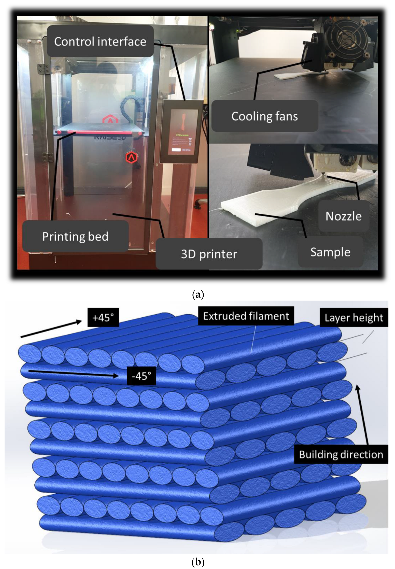
2. Experimental Layout

The printing concept using FDM technology is illustrated in Figure 1a. Two main parameters determine the 3D filament arrangement within the part (Figure 1b). The first is the in-plane filament arrangement exemplified by the raster. The second is the out-of-plane filament packing materialised by the building direction. The geometry of the part to be printed is a typical dog-bone structure. Depending on the relative orientation of the dog-bone structure with respect to the building direction, three main orientations can be selected: vertical (VE), longitudinal (LO), and lateral (LA). The filament arrangement within the plane of construction can be selected with the help of the printing angle parameter. Four different levels of printing angles are selected: 0°, 15°, 30°, and 45°. These levels correspond to filament crossings at −45°/+45°, −30°/+60°, −15°, +75°, and 0°/+90°, respectively. By combining the part orientation and the printing angle, nine different filament arrangements can be achieved, which are illustrated in Figure 1c. The nomenclature CER-XX-YY is used to differentiate between the sample conditions, where CER is PLA-ceramic filament, XX is the printing angle, and YY is the printing orientation. The printing orientation can take one of the following labels: LO (longitudinal), VE (vertical), and LA (lateral).
The printing process is conducted using a commercially available printer (Raise 3D Pro2 Plus) allowing high printing temperatures as large as 330 °C. The feedstock material is a polylactic—ceramic filament (CER) from Frontierfila company. The recommended printing temperatures for this filament are above 200 °C with a mandatory heated bed. As for the ceramic type, analysis by Energy Dispersive X-Ray Analysis (EDX) performed on areas of 5 × 5 μm2 show the presence of the following elements: C, Mo, Zn, and Si, which suggests a mixture of ceramics of the form SiC, MoC, MoC2. The fixed printing conditions are shown in Table 1. As mentioned earlier, the varied printing parameters are the part orientation and the printing angle. Table 1 also summarises the levels considered in this study. The printed dog-bone structures are subjected to tensile loading using a universal machine (Zwick Roell Group, Ulm, Germany). The standard ISO 527-1/-2 is adopted to perform tensile tests. This machine is equipped with a load cell of 10 kN. The rate of displacement is adjusted to 5 mm/min. The experiment is conducted up to the rupture point of the sample. The number of tested samples is 24 with two replicates per printing configuration. Out of the testing, stress—strain curves are built (Figure 1c) and the engineering constants, such as Young’s modulus, tensile strength, elongation at break are extracted and related to the printing conditions. It has to be mentioned that preliminary testing of the 3D printed samples shows that due to the local control of material laying down in 3D printing, there is a great confidence in the results achieved even with two prints per condition. The source of error has to come from another source which is more related to the testing setup. Indeed, several bias can be associated with tensile experiments such as if the sample length is misaligned with the loading direction, varied gauge length, etc. These are fixed in this study by monitoring the sample positioning by optical camera to ensure that the same testing conditions hold for each replicate (Figure 1d).
All experiments are monitored using optical observation. A high-speed camera (Phantom V7.3, Photonline, Marly Le Roi, 78-France) operating at a full frame of 800 × 600 pixels is used where the frame rate is adjusted between 100 and 5000 fps (frames per second).
The fractured surfaces of the tested samples are characterised using scanning electron microscopy (SEM) to reveal the relationship between the symmetry of the material and the loading configuration. SEM observations are performed on a QuattroS ESEM (ThermoScientific) microscope. Images are recorded using the low vacuum detector to avoid any deformations of the sample at high vacuum and metallization. An acceleration voltage from 5 to 8 kV is applied and a pressure of 100 Pa. Each sample is cut and taped on a carbon sheet support placed on the sample holder.

3. Results and Discussion

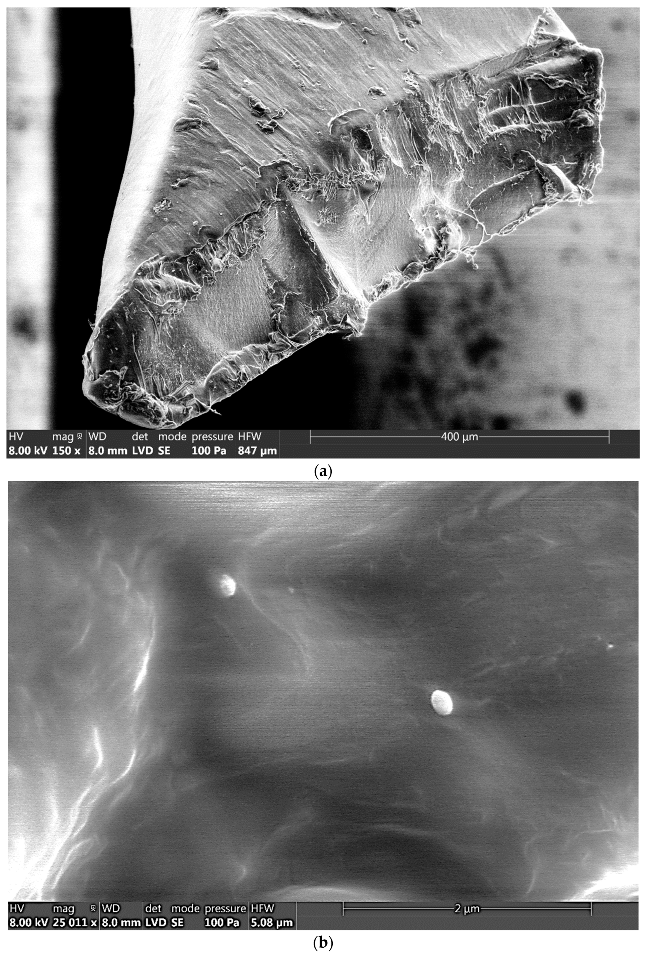
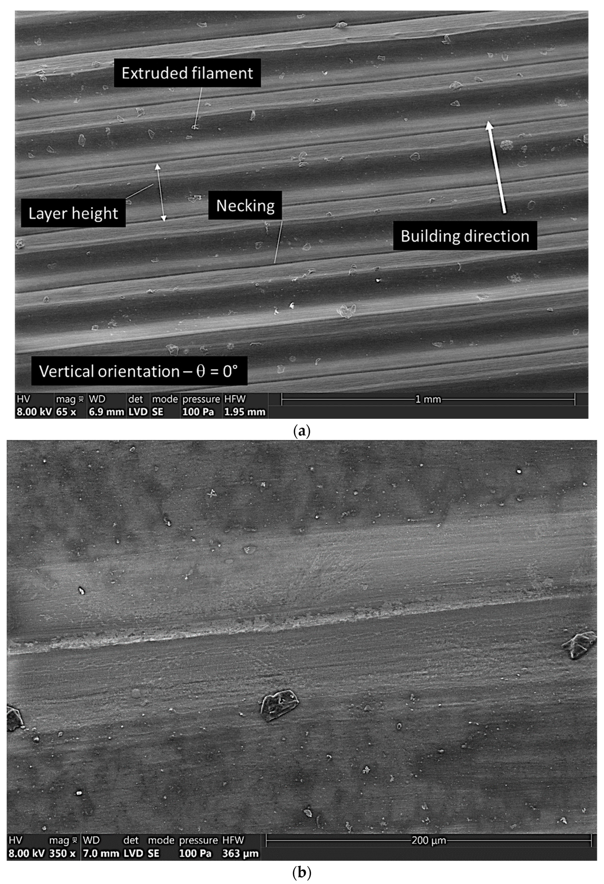
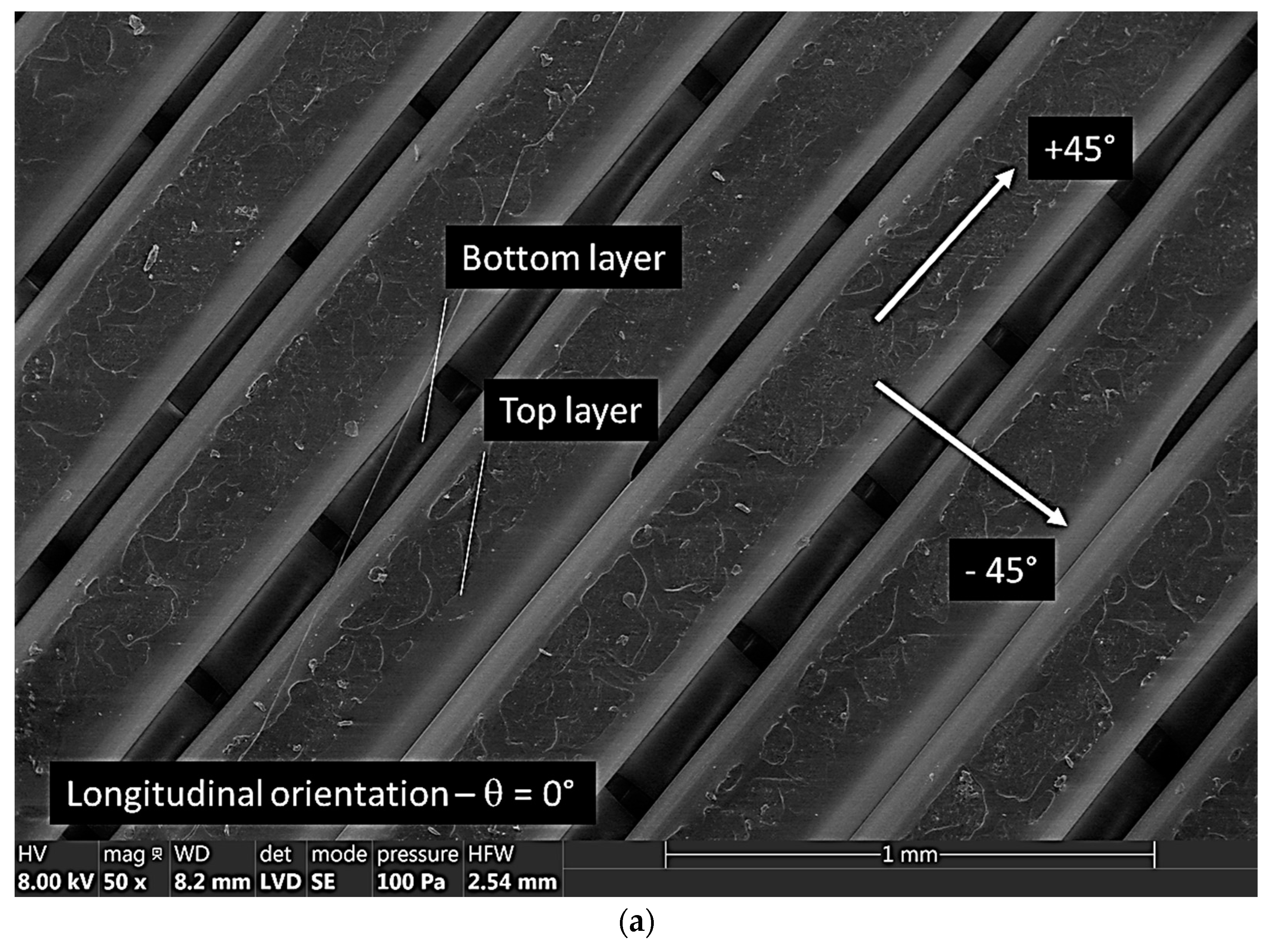
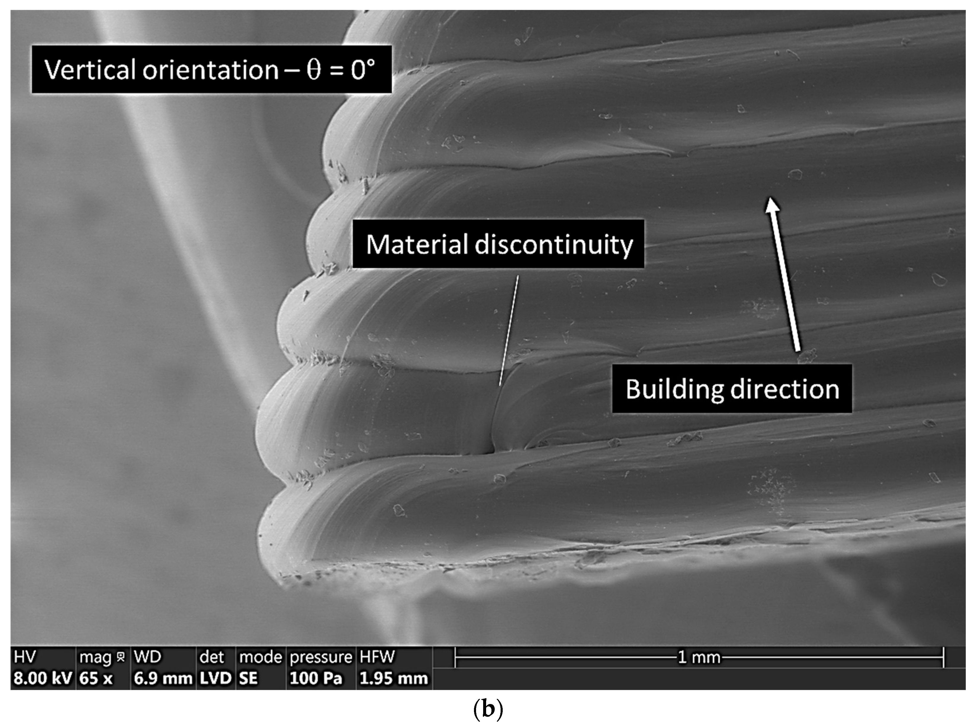
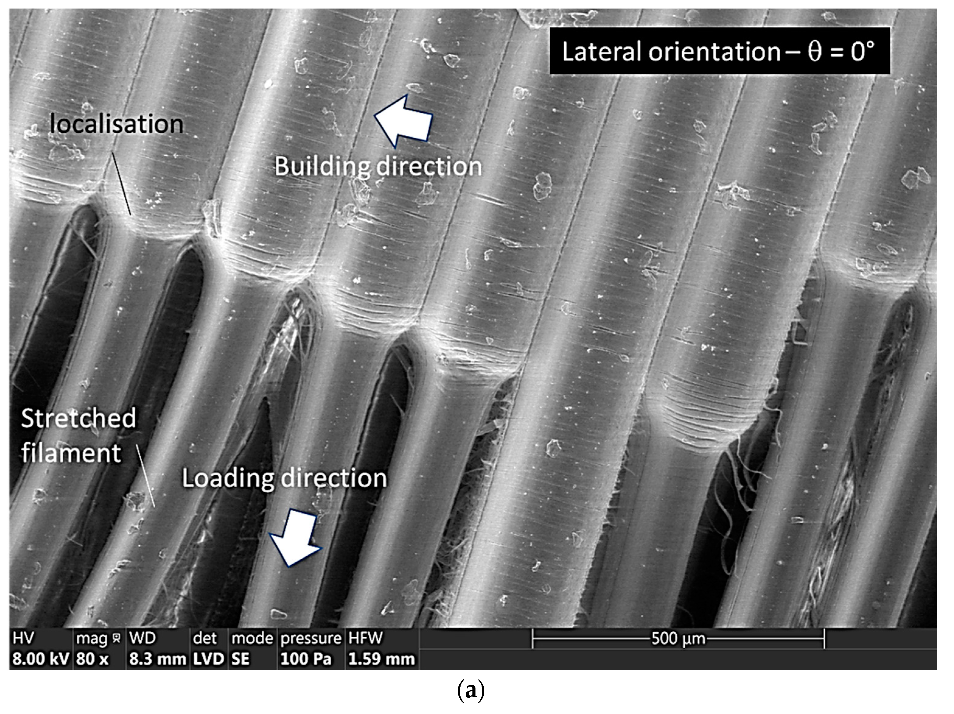
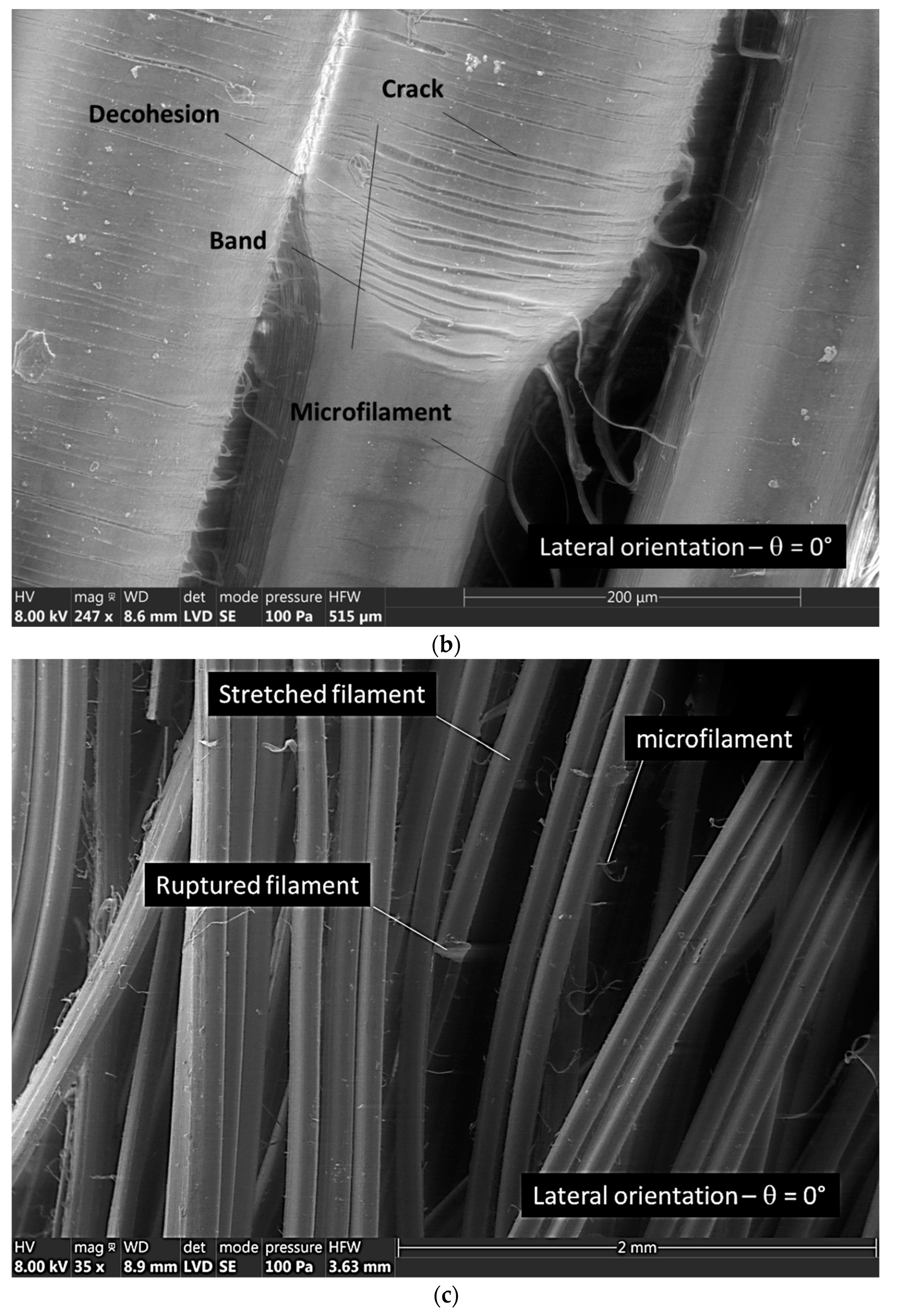
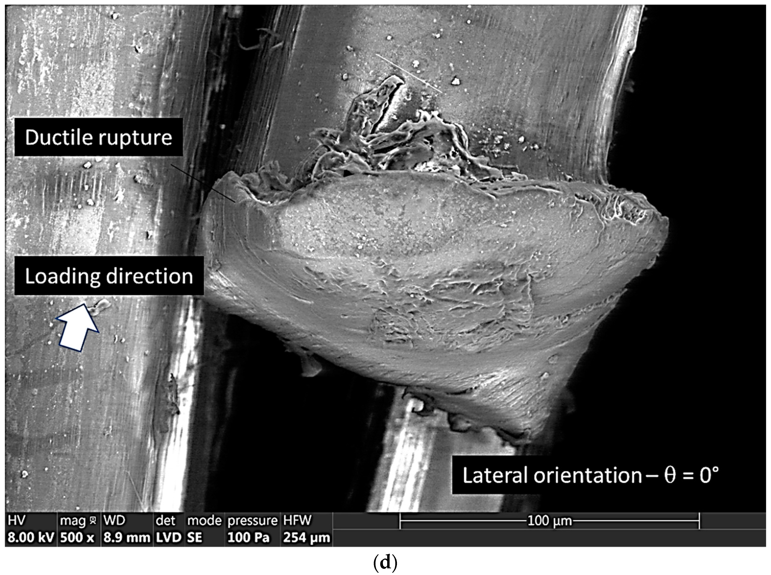
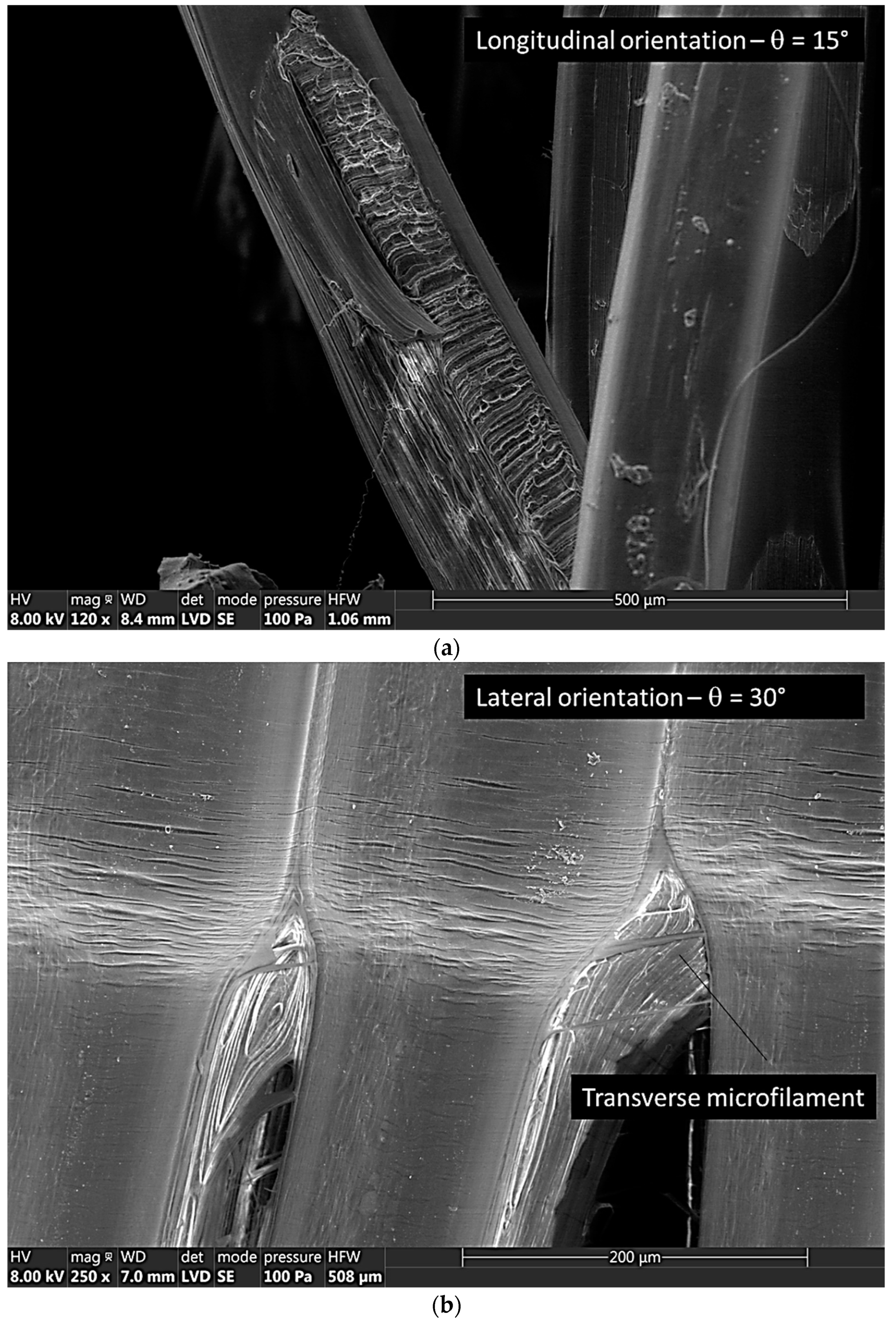
3.1. Microstructural Features

Figure 2a illustrates the modification of the PLC filament shape from nearly circular to elliptical due to the strategy of laying down. Indeed, the layer height is adjusted to half of the nozzle diameter, which forces the layers to have a larger contact along the building direction. In former studies [26,27,28], the layer height is introduced as a key parameter to control the overlapping between filaments in the building direction. A value lower than the nozzle diameter is found to improve both the mechanical performance and the surface finish. In this study, the same strategy is used to improve the mechanical stability of the 3D printed parts. The consequence is the change in the filament shape factor that affects the packing of the filaments, and in turn the generated porosity network. Within the filament, the ceramic particles are not affected by the increase of the temperature during the printing stage (Figure 2b). These appear as globular particles with a typical dimension of the order of 1 µm and a volume content of 15% according to the manufacturer datasheet. The examination of the interface between PLA and ceramic particles does not reveal particular interfacial damage, which puts more weight on the effect of filament arrangement in triggering the mechanical performance.
Figure 3 shows the out-of-plane layered structure corresponding to the vertical orientation, which is taken at an area far from the rupture region. Continuity in material structuring goes normal to the building direction (Figure 3a). The distance between adjacent filaments is nearly 200 µm, which also refers to the layer height. The central part of the filament appears smooth. However, the junction between adjacent filaments highlights a gap called necking. A close view of the necking (Figure 3b) reveals a textured white large structure of about 100 µm in width. This area emerges as a result of the deformation induced by the packing as the filament is forced to reduce its lateral dimension for 400 µm to 200 µm in the building direction. The cohesion between the filaments in this direction is only ensured by the limited contact area, which makes the 3D printed structure vulnerable to uniaxial loading along the same direction.
The in-plane arrangement of filaments for a sample printed according to the longitudinal orientation is shown in Figure 4. In order to highlight the filament crossing at +45°/−45° within the raster, the observed area is selected near the ruptured region where the stretching of the filaments allows both bottom and top layers to be viewed. Besides the limited connectivity between adjacent filaments within the same layer, filaments are cohesively connected between layers, where the contact area is substantially larger than for printed samples according to the vertical orientation. This connectivity confers to the printed part a tuneable performance depending on the relative orientation between the loading direction and the raster angle [29,30].
In addition to the raster that is defined by the in-plane filament arrangement within the core of the sample, an external frame is added to confer more structural stability. Figure 4b shows the structure of this external frame along the edges in the case of a sample printed according to the vertical orientation. At the edges of the printed structure, the filament dimension is affected by both the compression of the top layers and the deceleration of the printing nozzle that occurs when trajectory changes drastically close to the edge. In addition, after the completion of the frame, the printing nozzle moves to the next position, which leaves a discontinuity as the one shown in Figure 4b.

3.2. Effect of Part Orientation

Figure 5a shows the effect of the vertical orientation on the fracture patterns of PLC printed samples. As the loading is performed in the same direction of material building, the load transfer is directed into a large area where the cohesion between filament is limited. As a consequence, this building configuration results in a limited mechanical strength and the instable cracking along the necking occurs substantially causing the ruin of the material (Figure 5b). This leads to a limited performance as observed in several studies, for instance in bending loading configuration when upright position is selected [31], or in tensile configuration leading to the lowest mechanical strength scores [32]. The uniaxial loading is also transferred to the sample edge, which leads to the filament decohesion observed in Figure 5c. It can be concluded that for the vertical orientation, the structural role of the external frame is limited because the load bearing does not exploit the longitudinal performance of the filament.
Figure 6a shows the effect of the lateral orientation on the fracture patterns of PLC printed structures. In this case, the loading direction is no more aligned with the building direction. This means that the uniaxial stretching of the filament along its length represents most of the load transfer. This result is confirmed by several studies such as by Eryildiz [33], which shows the improvement of the tensile performance of PLA when the specimen is printed throughout its edge compared to the upright configuration. This is also confirmed by Yao et al. [34] in the case of PLA printing according to different out-of-plane angles, where the configuration similar to the one considered here calls for an out-of-plane angle of 90°. Because the volume fraction of PLA matrix is predominant, the amount of stretching induces a severe plasticity behaviour, which is followed by a localisation phenomenon as shown in Figure 6a. The strain localisation induces significant reduction in filament cross-section prior rupture. A closer view at the junction between original and reduced sections of the filament highlights the presence of series of transverse cracks organised in bands (Figure 6b). The filament section reduction allows a large filament volume to be heterogeneously stretched along the length. This section reduction also has another consequence on the filament cohesion in the transverse direction. As shown in Figure 6b, a decohesion front develop in the direction opposite to the loading direction. Between adjacent filaments, the decohesion can be complete or partial, and can possibly leads to the formation and detachment of microfilaments as shown in Figure 6b.
Far from the localisation area, the overstretching of filaments involves mostly the filaments belonging to the external frame (Figure 6c). When the amount of stretching reaches the ultimate elongation at break of the filaments, the rupture pattern captured in Figure 6d eventually occurs. This pattern is typical of a ductile behaviour associated with the PLA matrix behaviour.
Figure 7a shows the last configuration among the possible part orientations, which is the longitudinal orientation. In this configuration, the filaments are stretched in a predominant +45°/−45° arrangement. This means that only a partial load transfer is obtained in the loading direction. This partial load transfer limits the stretching of the filaments compared to the previous filament arrangement (Figure 7a). A zoom-in view on the ruptured filaments shows the change of orientation of the filament observed in Figure 7b, which is a distinctive feature of the longitudinal orientation. This orientation shows also superior performance compared to the vertical orientation. This is confirmed by Ambrus et al. [35] in the case of a PLA-copper filament, where the tensile strength was found superior for the horizontal orientation. In addition, out-of-plane decohesion between successive layers generates an inhomogeneous deformation for which the extent is guided by the width of the contact area. In fact, the filaments are overstretched between the contact points which act as anchoring points. Figure 7c provides proof of the development of inhomogeneous stretching, for which the overstretched areas can be as large as 2 mm. A closer view of the overstretched filament does not show the presence of significant cracking bands. In addition, the transition between overstretched and under-stretched areas is abrupt.

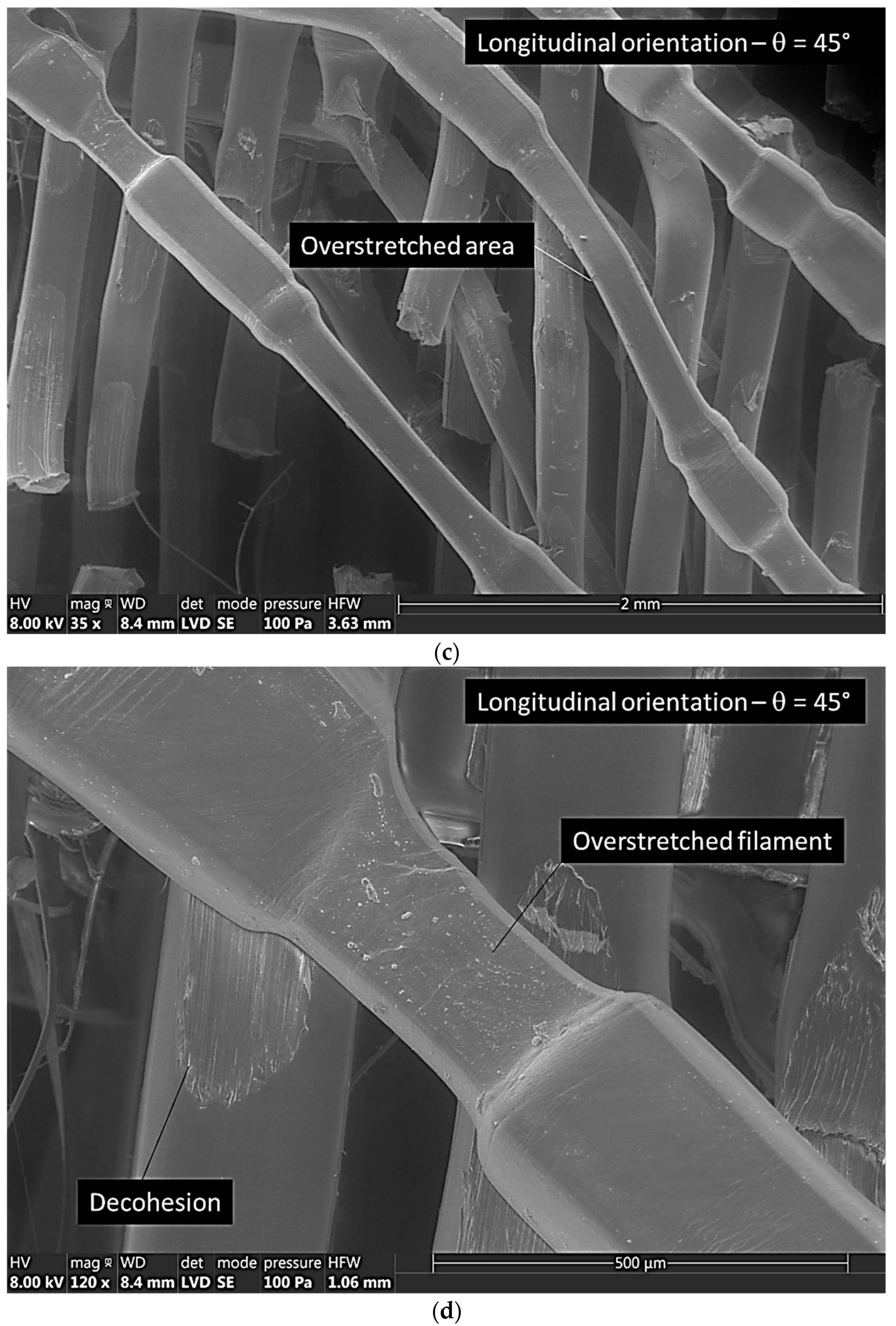
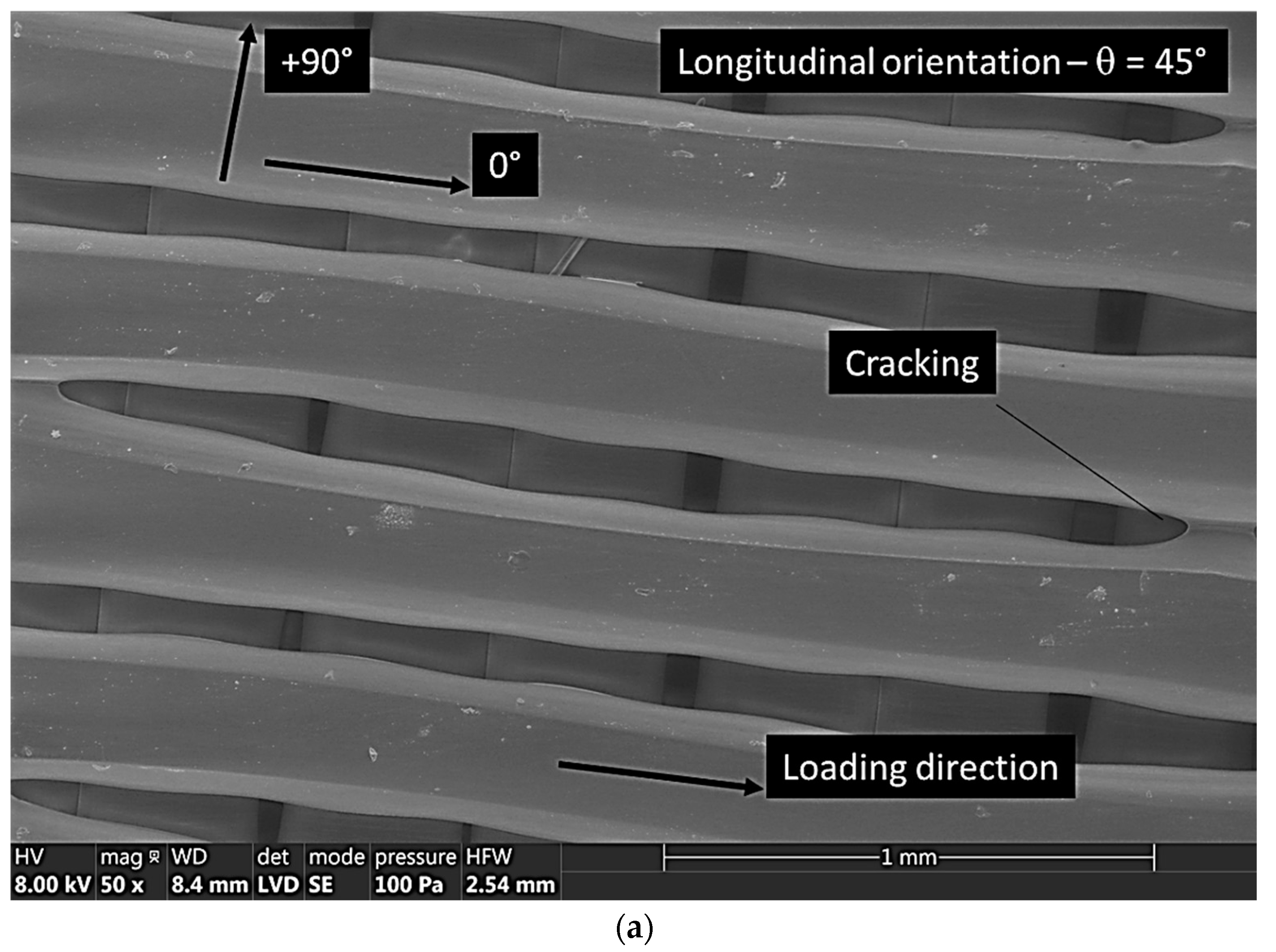
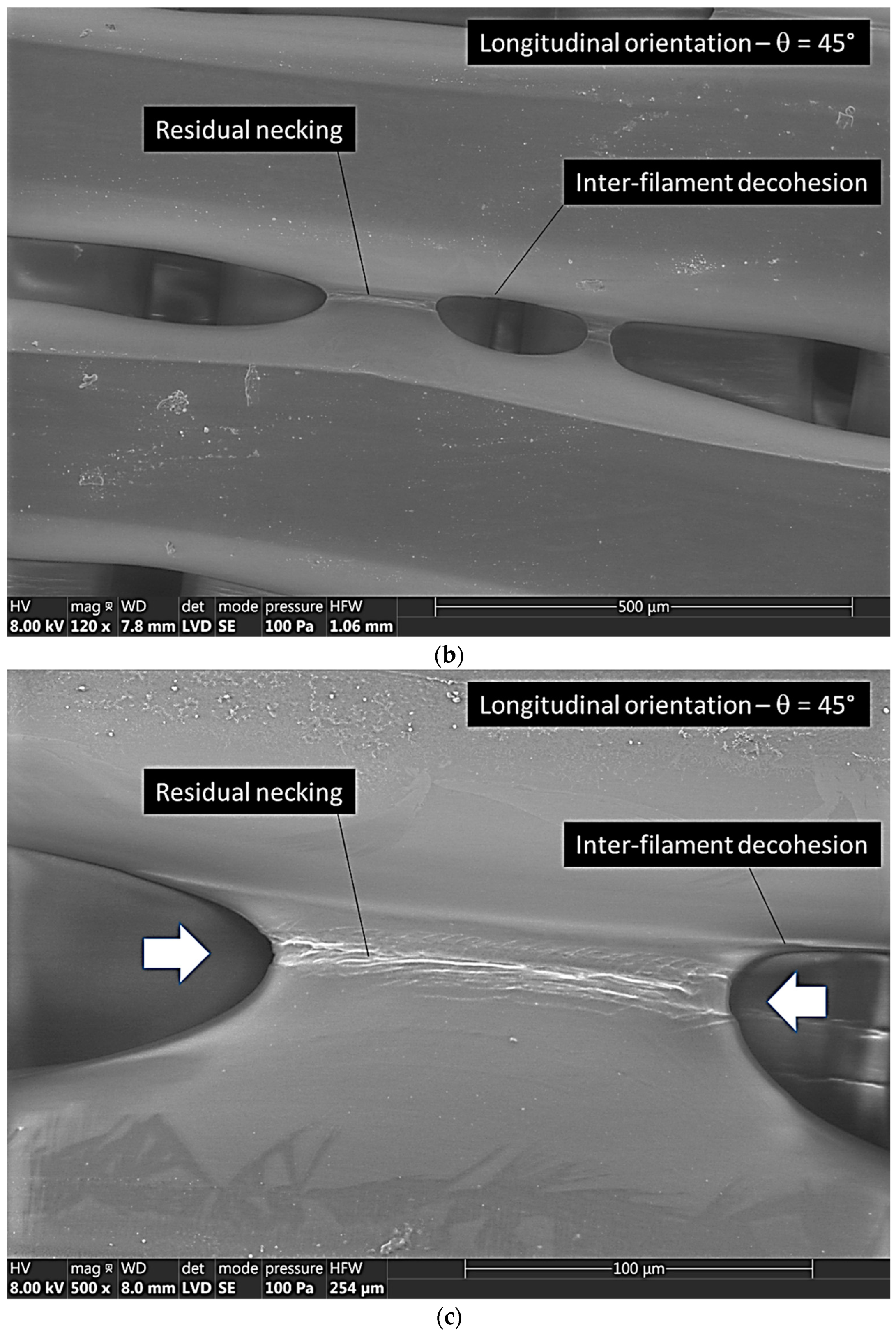
3.3. Effect of Printing Angle

Depending on the part orientation, the effect of the printing angle can be amplified or inhibited. For a sample printed in the longitudinal direction, the in-plane arrangement of the filaments significantly influences the load transfer. The printing angle associated to the longitudinal orientation can alter significantly the magnitude of the load transfer as well as the nature of the deformation mechanisms. This is, for instance, highlighted in the study by Khosravani et al. [36], which show the dependence of the cracking behaviour with respect to the raster angle. Figure 8 illustrates such influence for a part printed according to the longitudinal direction with a printing angle of 45°. The filament arrangement corresponding to this printing angle generates layups of 0°/90°. This arrangement allows half of the filaments to be oriented along the loading direction, which contributes significantly to the load bearing. It also generates a particular deformation mechanism that trigger inter-filament cracking due to the retraction of the filament in the transverse direction. This retraction induces inter-filament decohesion, which travels in the loading direction (Figure 8a). This situation occurs at multiple spots driven by the lack of connectivity between the filament on top of each other. The longitudinal cracks that are created along the loading direction grow in number and possibly connect to each other as suggested in Figure 8b. Below these cracks, where another mechanism of inter-filament decohesion occurs in the transverse direction. However, the resulting crack propagates faster because the filament necking is normal to the loading direction. This explains the low performance of such printing configuration as observed by Iyer et al. [37] for the short carbon fibre reinforced acrylonitrile butadiene styrene (ABS) filament. Figure 8c shows a closer view of the residual necking, which hosts a large number of microcracks that are formed by the reduction in filament section. According to this process, the crack bridging in the longitudinal direction adds more complexity to the deformation mechanisms induced by uniaxial loading.
Figure 9a shows the effect of an intermediate printing angle between 0° and 45° for a sample printed according to the longitudinal orientation. This figure exhibits partial detachment of the filament, which is induced by a large contact area between two successive filaments. This induces particular fracture patterns with significant deviation as illustrated in the former work by Khosravani et al. [36] for raster angles between 30° and 60°. The amount of damage observed is directly related to the extent of connectivity that is induced by the printing angle. In Figure 9b, the combination of lateral orientation with a printing angle of 30° allows more filaments to be more aligned with the loading direction. As a consequence, the localisation phenomenon introduced earlier results in the partial detachment of filaments according to the same mechanism shown in Figure 6b. However, the larger load transfer triggered by a larger printing angle (30°) allows more the microfilaments to act transversely against longitudinal cracking. This is further enhanced when the printing angle is increased to 45° (Figure 9c).

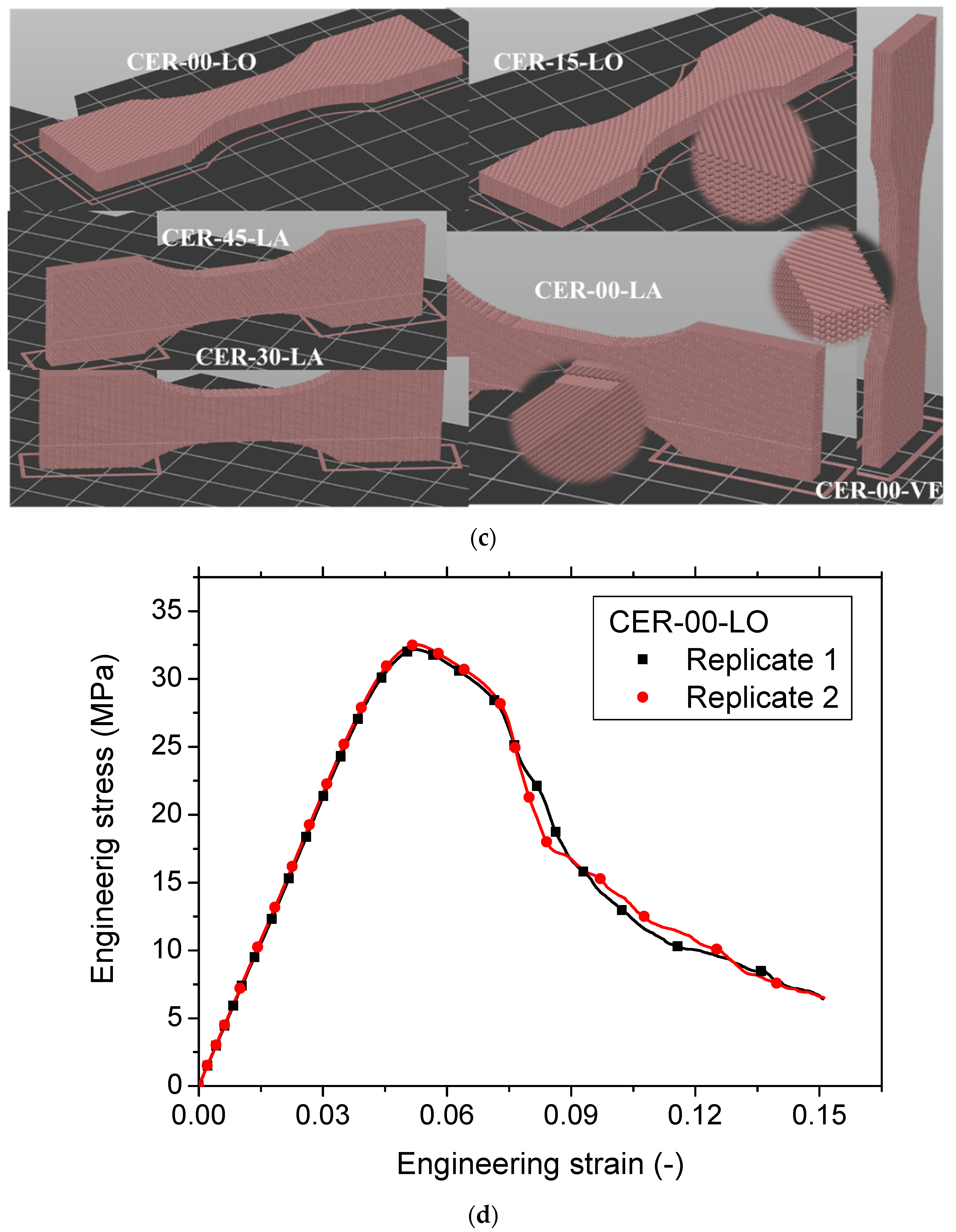
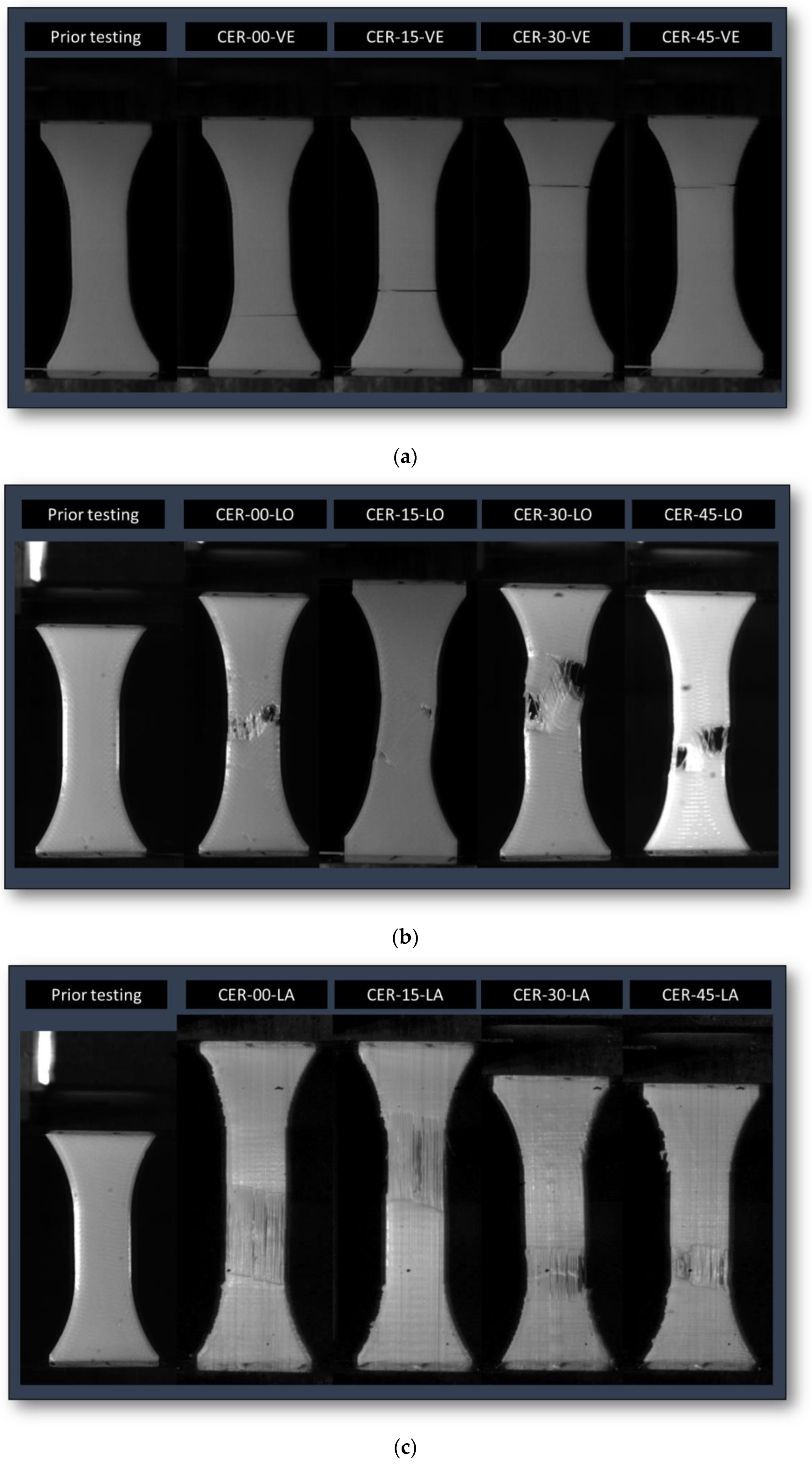
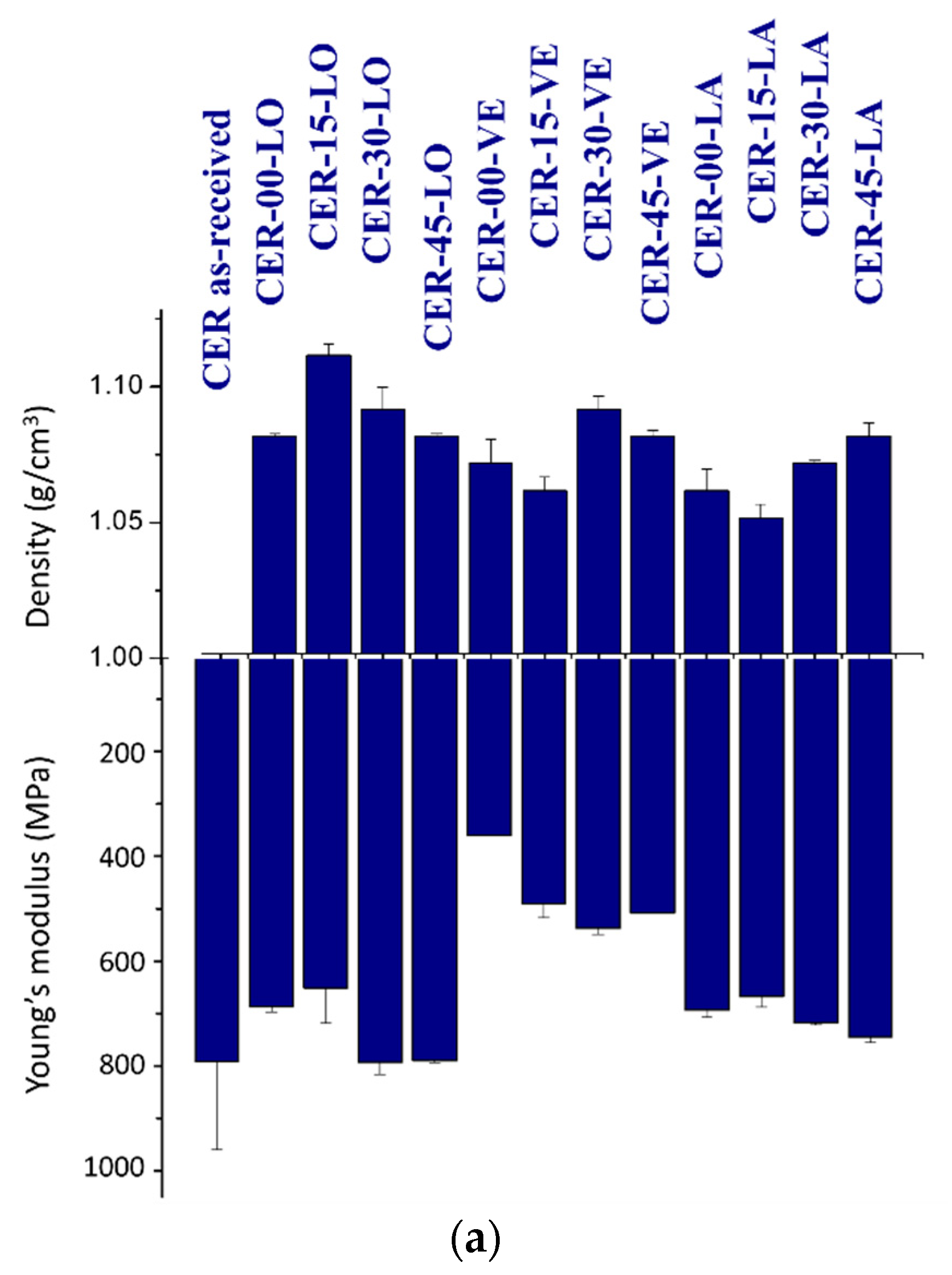
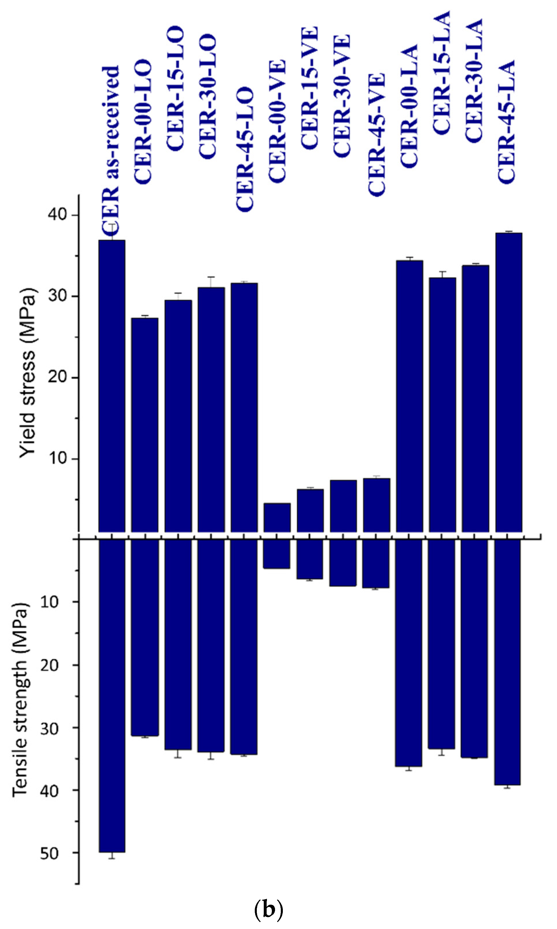
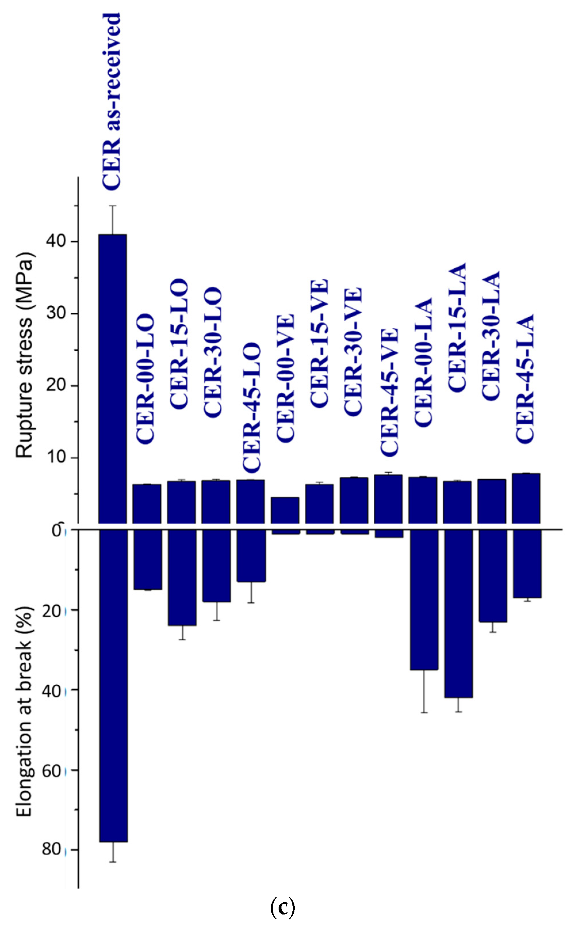
3.4. Consequence on Mechanical Behaviour

Figure 10 illustrates the consequence of printing configurations on the overall tensile behaviour. Figure 10a demonstrates that irrespective of the printing angle, the deformation behaviour of printed structures according to the vertical orientation share the same cracking behaviour and the limited stretching prior rupture. It can be stated that when the building direction is parallel to the loading direction, the printing angle has no significant effect on the tensile response. However, this printing orientation leads in all cases to limited performance. This is confirmed by several studies irrespective of the filament material [31,32,33]. The opposite situation is shown in Figure 10b for samples printed according to the longitudinal orientation. In this case, the plane of construction contributes significantly to the overall load bearing as shown by several contributions [34,35]. Indeed, according to this orientation, the plane defining the filament arrangement contains the direction of loading. This means that the overall tensile behaviour depends on the printing angle as shown in Figure 10b. For instance, cracking behaviour is directly related to the printing angle. In addition, shearing develops for particular printing angles such as 0°, 15°, and 30°, whereas for 45°, uniaxial deformation prevails. Additionally, the large deformation observed in the case of longitudinal orientation compared to Figure 10a is directly related to the stronger contribution of the filament stretching in the load transfer. The most contrasting case is related to the lateral orientation (Figure 10c). This orientation allows the filaments belonging to the frame to be fully oriented in the loading direction. As a consequence, a large stretching prior ruptured is observed for all printing configurations. In addition, similarly to Figure 10b, there is a correlation between the printing angle and the amount of deformation that the printed structures can ensure prior rupture.
Figure 11 summarises the quantified effects of both the printing angle and printing orientation on the mechanical parameters extracted from the mechanical responses. There is no clear trend between the density of the printed structures and the printing angle (Figure 11a). However, on average, it is found that the printed structures according to the lateral orientation exhibits the lowest densities (ρ = 1.06 ± 0.009 g/cm3). The same parts printed according to the longitudinal orientation exhibit the highest densities (ρ = 1.09 ± 0.013 g/cm3). This can be attributed to the amount of support needed to stabilise the structure during the printing process. The removal of this support can alter the density of the material. The intermediate case corresponds to the vertical orientation (ρ = 1.07 ± 0.012 g/cm3). Considerations about large discontinuities in the filament trajectories and the limited length laid down within the plane of construction can explain the lower density associated with this printing orientation. Regarding the mechanical performance, although it appears that there is no strong trend with respect to the printing angle, the reported results in Figure 11 suggest that higher performance is expected from a large printing angle. This is, for instance, true for Young’s modulus at θ = 30° and θ = 45°, irrespective of the printing orientation (Figure 11a). In the case of the longitudinal orientation, the stiffness performance of the as-received filament is even restored for these angles. In average, samples printed according to the longitudinal orientation are the top ranked ones (EY = 730 ± 72 MPa). The lowest ranked ones correspond to the vertical orientation (EY = 474 ± 78 MPa), which corresponds to a 40% of loss in the stiffness with respect to the as-received filament performance.
The fitting procedure allows to capture the general trend of Young’s modulus dependence on the printing angle, as follows.
For longitudinal orientation, the linear approximation is verified with a large correlation factor:
E Y MPa = 688 + 2.27 × θ d e g . ;   R 2 = 0.96  
For the lateral orientation, the linear trend is not obvious due to the small value of the correlation factor:
E Y MPa = 679 + 1.31 × θ d e g . ;   R 2 = 0.76  
For the vertical orientation, the linear fitting routine fails.
Thus, the overall trend of Young’s modulus dependence on the printing angle is verified but the linear fitting result does not suggest a strong dependence.
The analysis of the yield performance shows that the same rationale holds for the effect of the printing angle (Figure 11b). However, the yield stress is found to be the largest one for the lateral orientation (σY = 35 ± 2.32 MPa) whereas it decreases to σY = 6 ± 1.4 MPa for the vertical orientation. For both cases, the yielding performance of the CER as-received filament are not restored. The loss in the yielding performance represents 6% and 82%, respectively.
The fitting analysis performed to show the dependence of yield stress on the printing angle generate the following trend.
For longitudinal orientation, the linear approximation is nearly perfect:
σ Y MPa = 28 + 0.09 × θ d e g . ;   R 2 = 0.98  
For the lateral orientation, the linear trend is not obvious due to the small value of the correlation factor:
σ Y MPa = 33 + 0.09 × θ d e g . ;   R 2 = 0.48  
For the vertical orientation, the linear fitting routine fails.
Thus, the overall trend for yield stress is thus similar to that of Young’s modulus with regards to the dependence on the printing angle.
The tensile strength of the printed material follows the same tendency, where the gap between the yield stress and the tensile strength is limited for the longitudinal ( σ M σ Y / σ M = 11 ±   3 % ) and lateral ( σ M σ Y / σ M = 4 ±   1 % ) orientation (Figure 11b). The samples printed according to the vertical orientation do not present a plasticity behaviour. This means that the plasticity behaviour is significantly affected by the printing orientation. The best performing structures are those printed according to the lateral orientation (σM = 36 ± 2.47 MPa) whereas the less performing ones are those printed according to the vertical orientation (σM = 6 ± 1.41 MPa). This corresponds to a 28% and 87% of loss in the tensile strength with respect to the as-received filament performance, respectively.
The fitting analysis performed on the tensile strength shows the following results.
For longitudinal orientation, the linear function works fine:
σ M MPa = 32 + 0.06 × θ d e g . ;   R 2 = 0.96  
For the lateral orientation, the linear trend is realistic due to the small correlation factor (R2 = 0.31) whereas it fails again for the vertical orientation.
The low values of ultimate stress (σR) compared to the tensile strength observed for the lateral and longitudinal orientation demonstrates the development of localisation behaviour as shown in Figure 6 and Figure 7. There is no clear difference between the printing orientations and all configurations rank the same (σR = 7 ± 0.84 MPa). The ultimate stress is significantly reduced by 83% compared to the as-received filament properties (Figure 11c).
The linear fitting function provides the trend of the ultimate stress with respect to the printing angle.
For longitudinal orientation, the linear approximation is successful:
σ R MPa = 6.3 + 0.01 × θ d e g . ;   R 2 = 0.98  
For the other orientations, the linear trend produces the same unrealistic result similarly to the tensile strength.
The elongation at break follows the same trend as the tensile strength (Figure 11c). It is significantly reduced for the vertical orientation (εR = 1 ± 0.12%), which represents 98% of reduction with respect to the as-received filament properties. The same elongation at break increases to its maximum level for the lateral orientation (εR = 29 ± 11.71%), allowing to limit the performance loss to 62%.
The linear fitting procedure does not provide a clear trend of both longitudinal and lateral orientations. However, it does for the vertical orientation:
ε R % = 47 0.06 × θ d e g . ;   R 2 = 0.90  

4. Conclusions

This study demonstrates that the modulation of the mechanical performance of 3D printed ceramic materials can be obtained by combining both the part orientation and printing angle with respect to the loading direction. The SEM micrographs of fractured patterns conclude on varieties of deformation mechanisms that are activated and enhanced by playing on the relative orientation of the filaments with respect to the loading direction. These mechanisms are explained by the lack of material connectivity both in the building direction and within the plane of construction. The worst performing printing configurations are those printed according to the vertical orientation, in which the limited load transfer affects severely the stiffness, strength and ultimate performance. This is proved from SEM observations showing that the load is directed into a large area where the cohesion between filament is limited. The lateral orientation appears to be the best compromise if the strength and ultimate properties are the main target. The maximum modulation of the tensile performance is found for the longitudinal orientation, where it is possible to significantly change the resulting performance by adjusting the printing angle. This configuration also fully restores the stiffness of the ceramic reinforced polymer filament, especially for two printing angles, namely θ = 30° and θ = 45°, where the same Young’s modulus of the as-received filament is obtained for the 3D printed structures.

Author Contributions

Conceptualization, S.G. and S.B.; methodology, L.H., S.G., A.D. and S.B.; software, L.H., S.G., A.D. and S.B.; validation, S.B. and S.G.; formal analysis, L.H., S.G., A.D. and S.B.; investigation, L.H., S.G., A.D. and S.B.; resources, L.H., S.G., A.D. and S.B.; data curation, S.G., S.B.; writing—original draft preparation, S.G.; writing—review and editing, L.H., S.G., A.D. and S.B.; visualization, L.H., S.G.; supervision, S.G.; project administration, S.G.; funding acquisition, L.H., S.G. All authors have read and agreed to the published version of the manuscript.

Funding

This research received no external funding.

Institutional Review Board Statement

Not applicable.

Informed Consent Statement

Not applicable.

Data Availability Statement

Not applicable.

Conflicts of Interest

The authors declare no conflict of interest.

References

  1. Yan, X.; Gu, P. A review of rapid prototyping technologies and systems. Comput. Aided Des. 1996, 28, 307–318. [Google Scholar] [CrossRef]
  2. Praveena, B.A.; Lokesh, N.; Buradi, A.; Santhosh, N.; Praveena, B.L.; Vignesh, R. A comprehensive review of emerging additive manufacturing (3d printing technology): Methods, materials, applications, challenges, trends and future potential. Mater. Today Proc. 2021, 52, 1309–1313. [Google Scholar]
  3. Zhai, Y.W.; Lados, D.A.; Lagoy, J.L. Additive manufacturing: Making imagination the major limitation. JOM 2014, 66, 808–816. [Google Scholar] [CrossRef] [Green Version]
  4. Turner, B.N.; Gold, S.A. A review of melt extrusion additive manufacturing processes: II. Materials, dimensional accuracy, and surface roughness. Rapid Prototyp. J. 2015, 21, 250–261. [Google Scholar] [CrossRef]
  5. Gao, W.; Zhang, Y.; Ramanujan, D.; Ramani, K.; Chen, Y.; Williams, C.B.; Wang, C.C.L.; Shin, Y.C.; Zhang, S.; Zavattieri, P.D. The status, challenges, and future of additive manufacturing in engineering. Comput. Aided Des. 2015, 69, 65–89. [Google Scholar] [CrossRef]
  6. Gibson, I.; Rosen, D.; Stucker, B. Additive Manufacturing Technologies; Springer: Berlin/Heidelberg, Germany, 2010. [Google Scholar]
  7. Subramaniyan, M.; Karuppan, S.; Eswaran, P.; Appusamy, A.; Naveen Shankar, A. State of art on fusion deposition modeling machines process parameter optimization on composite materials. Mater. Today Proc. 2020, 45, 820–827. [Google Scholar] [CrossRef]
  8. Mazzanti, V.; Malagutti, L.; Mollica, F. Fdm 3d printing of polymers containing natural fillers: A review of their mechanical properties. Polymers 2019, 11, 1094. [Google Scholar] [CrossRef] [Green Version]
  9. Solomon, I.J.; Sevvel, P.; Gunasekaran, J. A review on the various processing parameters in fdm. Mater. Today Proc. 2020, 37, 509–514. [Google Scholar] [CrossRef]
  10. Chaunier, L.; Guessasma, S.; Belhabib, S.; Valle, G.D.; Lourdin, D.; Leroy, E. Material extrusion of plant biopolymers: Opportunities & challenges for 3d printing. Addit. Manuf. 2018, 21, 220–233. [Google Scholar]
  11. Gao, X.; Qi, S.; Kuang, X.; Su, Y.; Li, J.; Wang, D. Fused filament fabrication of polymer materials: A review of interlayer bond. Addit. Manuf. 2021, 37, 101658. [Google Scholar] [CrossRef]
  12. Nouri, H.; Guessasma, S.; Belhabib, S. Structural imperfections in additive manufacturing perceived from the x-ray micro-tomography perspective. J. Mater. Process. Technol. 2016, 234, 113–124. [Google Scholar] [CrossRef]
  13. Vyavahare, S.; Teraiya, S.; Panghal, D.; Kumar, S. Fused deposition modelling: A review. Rapid Prototyp. J. 2020, 26, 176–201. [Google Scholar] [CrossRef]
  14. Ahn, S.-H.; Montero, M.; Odell, D.; Roundy, S.; Wright, P.K. Anisotropic material properties of fused deposition modeling abs. Rapid Prototyp. J. 2002, 8, 248–257. [Google Scholar] [CrossRef] [Green Version]
  15. Anna, B.; Selçuk, G. Mechanical characterization of parts fabricated using fused deposition modeling. Rapid Prototyp. J. 2003, 9, 252–264. [Google Scholar]
  16. Heidari-Rarani, M.; Rafiee-Afarani, M.; Zahedi, A.M. Mechanical characterization of fdm 3d printing of continuous carbon fiber reinforced pla composites. Compos. Part B Eng. 2019, 175, 107147. [Google Scholar] [CrossRef]
  17. Sood, A.K.; Ohdar, R.K.; Mahapatra, S.S. Parametric appraisal of mechanical property of fused deposition modelling processed parts. Mater. Des. 2010, 31, 287–295. [Google Scholar] [CrossRef]
  18. Tanikella, N.G.; Wittbrodt, B.; Pearce, J.M. Tensile strength of commercial polymer materials for fused filament fabrication 3d printing. Addit. Manuf. 2017, 15, 40–47. [Google Scholar] [CrossRef] [Green Version]
  19. McLouth, T.D.; Severino, J.V.; Adams, P.M.; Patel, D.N.; Zaldivar, R.J. The impact of print orientation and raster pattern on fracture toughness in additively manufactured abs. Addit. Manuf. 2017, 18, 103–109. [Google Scholar] [CrossRef]
  20. Medellin-Castillo, H.I.; Zaragoza-Siqueiros, J. Design and manufacturing strategies for fused deposition modelling in additive manufacturing: A review. Chin. J. Mech. Eng. 2019, 32, 53. [Google Scholar] [CrossRef] [Green Version]
  21. Mohan Pandey, P.; Venkata Reddy, N.; Dhande, S.G. Slicing procedures in layered manufacturing: A review. Rapid Prototyp. J. 2003, 9, 274–288. [Google Scholar] [CrossRef] [Green Version]
  22. Abouzaid, K.; Guessasma, S.; Belhabib, S.; Bassir, D.; Chouaf, A. Printability of co-polyester using fused deposition modelling and related mechanical performance. Eur. Polym. J. 2018, 108, 262–273. [Google Scholar] [CrossRef]
  23. Gebisa, A.W.; Lemu, H.G. Influence of 3d printing fdm process parameters on tensile property of ultem 9085. Procedia Manuf. 2019, 30, 331–338. [Google Scholar] [CrossRef]
  24. Dawoud, M.; Taha, I.; Ebeid, S.J. Mechanical behaviour of abs: An experimental study using fdm and injection moulding techniques. J. Manuf. Process. 2016, 21, 39–45. [Google Scholar] [CrossRef]
  25. Lokesh, N.; Praveena, B.A.; Sudheer Reddy, J.; Vasu, V.K.; Vijaykumar, S. Evaluation on effect of printing process parameter through Taguchi approach on mechanical properties of 3d printed pla specimens using fdm at constant printing temperature. Mater. Today Proc. 2022, 52, 1288–1293. [Google Scholar] [CrossRef]
  26. Drugă, C.; Șerban, I.; Braun, B.; Tulică, A. Analysis of the Influence of the Layer Height on the Strength of 3d Printed Structures. In Proceedings of the 11th International Conference on Information Science and Information Literacy, Brașov, Romania, 11–12 March 2021; pp. 177–181. [Google Scholar]
  27. Bintara, R.D.; Lubis, D.Z.; Aji Pradana, Y.R. The effect of layer height on the surface roughness in 3d printed polylactic acid (pla) using fdm 3d printing. IOP Conf. Ser. Mater. Sci. Eng. 2021, 1034, 012096. [Google Scholar] [CrossRef]
  28. Nair, S.A.O.; Tripathi, A.; Neithalath, N. Examining layer height effects on the flexural and fracture response of plain and fiber-reinforced 3d-printed beams. Cem. Concr. Compos. 2021, 124, 104254. [Google Scholar] [CrossRef]
  29. Maurya, N.K.; Rastogi, V.; Singh, P. An overview of mechanical properties and form error for rapid prototyping. CIRP J. Manuf. Sci. Technol. 2020, 29, 53–70. [Google Scholar] [CrossRef]
  30. Doshi, M.; Mahale, A.; Kumar Singh, S.; Deshmukh, S. Printing parameters and materials affecting mechanical properties of fdm-3d printed parts: Perspective and prospects. Mater. Today Proc. 2022, 50, 2269–2275. [Google Scholar] [CrossRef]
  31. Katiyar, P.C.; Singh, B.P.; Chhabra, M.; Parle, D. Effect of build orientation on load capacity of 3d printed parts. Int. J. Recent Technol. Eng. (IJRTE) 2022, 10, 38–52. [Google Scholar] [CrossRef]
  32. Tanoto, Y.Y.; Anggono, J.; Siahaan, I.H.; Budiman, W. The effect of orientation difference in fused deposition modeling of abs polymer on the processing time, dimension accuracy, and strength. AIP Conf. Proc. 2017, 1788, 030051. [Google Scholar]
  33. Eryildiz, M. Effect of build orientation on mechanical behaviour and build time of fdm 3d-printed pla parts: An experimental investigation. Eur. Mech. Sci. 2021, 5, 116–120. [Google Scholar] [CrossRef]
  34. Yao, T.; Deng, Z.; Zhang, K.; Li, S. A method to predict the ultimate tensile strength of 3d printing polylactic acid (pla) materials with different printing orientations. Compos. Part B Eng. 2019, 163, 393–402. [Google Scholar] [CrossRef]
  35. Ambruş, S.; Muntean, R.; Codrean, C.; Uţu, I.-D. Influence of printing conditions on the mechanical properties of copper-polylactic acid composites obtained by 3d printing fused deposition modelling. Mater. Today Proc. 2022. [Google Scholar] [CrossRef]
  36. Khosravani, M.R.; Berto, F.; Ayatollahi, M.R.; Reinicke, T. Characterization of 3d-printed pla parts with different raster orientations and printing speeds. Sci. Rep. 2022, 12, 1016. [Google Scholar] [CrossRef] [PubMed]
  37. Srinivasan Ganesh Iyer, S.; Keles, O. Effect of raster angle on mechanical properties of 3d printed short carbon fiber reinforced acrylonitrile butadiene styrene. Compos. Commun. 2022, 32, 101163. [Google Scholar] [CrossRef]
Figure 1. (a) Illustration of the fused deposition modelling technique; (b) filament arrangement in 3D printed parts; (c) printing configurations using a combination of orientation and printing angle; and (d) typical stress—strain response for two replicates.
Symmetry 15 00028 g001aSymmetry 15 00028 g001b
Figure 2. Extruded PLC filament showing (a) the shape factor and (b) the ceramic particle shape.
Symmetry 15 00028 g002
Figure 3. Out-of-plane microstructural arrangement showing (a) the filament alignment along the building direction for a sample printed according to the vertical orientation and (b) a close view of the necking structure.
Symmetry 15 00028 g003
Figure 4. In-plane filament arrangement in (a) 3D printed sample according to the longitudinal orientation and (b) filament arrangement in the external frame.
Symmetry 15 00028 g004aSymmetry 15 00028 g004b
Figure 5. Fractured surfaces of samples printed according to the vertical orientation (i.e., building direction parallel to the loading direction): (a) zoom-out; and (b) zoom-in views at the central part of the printed sample; (c) a shifted view at the edge of the sample; and (d) a zoom-in view of the edge highlighting the filament decohesion along the neck.
Symmetry 15 00028 g005aSymmetry 15 00028 g005b
Figure 6. Fractured surfaces of a sample printed according to the lateral orientation: (a) zoom-out at the stretched area; (b) a close view at the localisation area; (c) a global view of the overstretched filaments; and (d) a zoom-in view on a ruptured filament.
Symmetry 15 00028 g006aSymmetry 15 00028 g006bSymmetry 15 00028 g006c
Figure 7. Fractured surfaces of a sample printed according to the longitudinal orientation: (a) zoom-out at the rupture area; (b) a close view at the ruptured area; (c) a global view of the overstretched filaments; and (d) a zoom-in view on a ruptured filament.
Symmetry 15 00028 g007aSymmetry 15 00028 g007b
Figure 8. Top view normal to the raster showing the layup of 0°/90° corresponding to a printing angle of 90°. (a) The formation of inter-filament cracking, which propagates in the loading direction; (b) a magnified view showing the bridging process between longitudinal cracks generated by the inter-filament decohesion; and (c) a magnified view showing the residual necking (region highlighted by arrows) in sandwich between two longitudinal cracks.
Symmetry 15 00028 g008aSymmetry 15 00028 g008b
Figure 9. Effect of the printing angle on the deformation mechanisms: (a) longitudinal orientation—printing angle of 15°; (b) lateral orientation—printing angle of 30°; and (c) lateral orientation—printing angle of 45°.
Symmetry 15 00028 g009aSymmetry 15 00028 g009b
Figure 10. Deformed structures captured at the end of the tensile loading showing the combined effect of printing angle and orientation: (a) vertical, VE; (b) longitudinal, LO; and (c) lateral, LA orientations.
Symmetry 15 00028 g010
Figure 11. Observed tensile performance of CER versus printing conditions. In the nomenclature CER-XX-YY, CER is PLA-ceramic filament, XX is the printing angle, and YY is the printing orientation. (a) The density and Young’s modulus; (b) yield stress and tensile strength; and (c) ultimate stress and elongation at break.
Symmetry 15 00028 g011aSymmetry 15 00028 g011bSymmetry 15 00028 g011c
Table 1. Fixed and varied printing conditions considered in this study.
PropertyLevel
Infill, IF (%)100
Nozzle diameter, DN (mm)0.4
Printing temperature, TP (°C)210
Layer height (mm)0.2
Bed temperature, TB (°C)60
Printing speed, VP (mm/s)50
Support density, SPD (%)10
Frame width, WF (mm)0.8
Orientation, OR (-)Vertical (VE), Longitudinal (LO), Lateral (LA)
Printing angle, AP (°)0, 15, 30, 45
Disclaimer/Publisher’s Note: The statements, opinions and data contained in all publications are solely those of the individual author(s) and contributor(s) and not of MDPI and/or the editor(s). MDPI and/or the editor(s) disclaim responsibility for any injury to people or property resulting from any ideas, methods, instructions or products referred to in the content.

