
Multi-Objective Reliability-Based Partial Topology Optimization of a Composite Aircraft Wing


Abstract
:1. Introduction
- A novel fuzzy-based metaheuristic (MRBPTOFBMH) approach is suggested to optimize composite aircraft wing structure.
- A non-probabilistic approach called possibilistic safety index-based design optimization (PSIBDO) with fuzzy uncertainties is proposed to improve the computational efficiency of the aircraft wing design.
- An efficient framework that facilitates easy integration with a multi-objective evolutionary algorithm (MOEA) is suggested.
- The effectiveness of the suggested methodology is evaluated using a multi-objective aircraft wing topology optimization case study.
2. Aeroelastic Partial Topology
2.1. Aircraft Wing Model
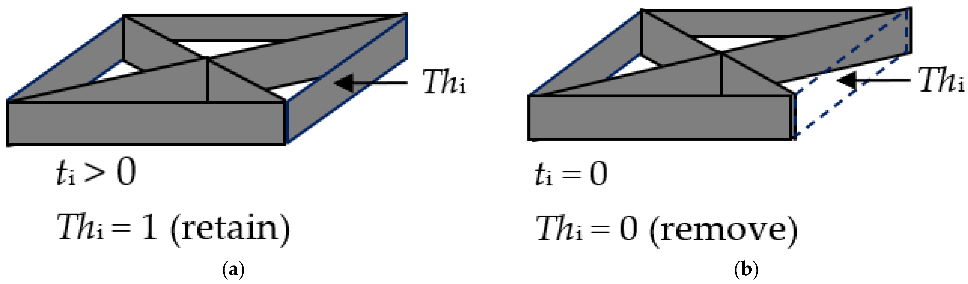
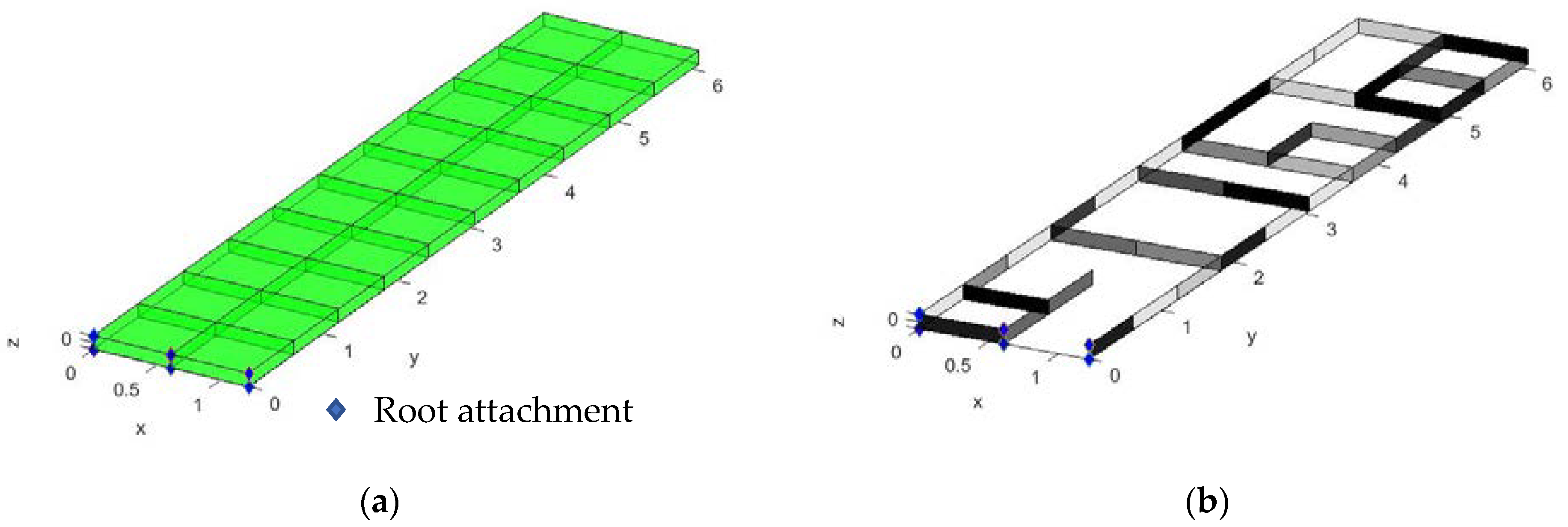
2.2. Partial Topology Design
2.3. Aerodynamic Model
2.4. Aeroelastic Analysis
2.5. Lift Effectiveness
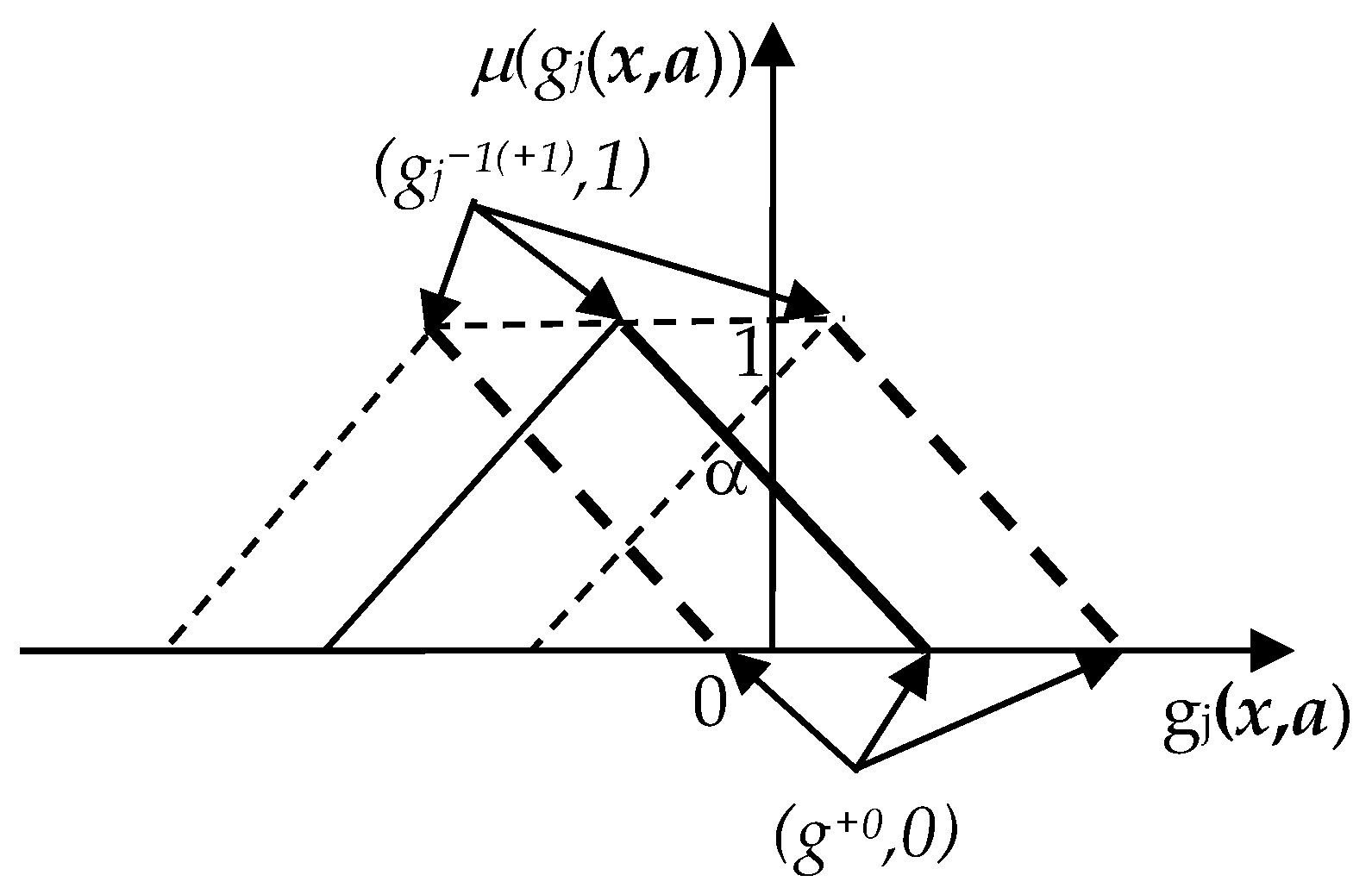
3. Multi-Objective Reliability-Based Partial Topology Optimization Using Fuzzy-Based Metaheuristic (MRBPTOFMH)
- (1)
- Start with the initial interval: let α1 = 0, α2 = 1; it should be noted that the specified tolerance is ε = 1 × 10⁻⁸.
- (2)
- Find α3 = (α1 + α2)/2.
- (3)
- If gjα1 × gjα3 < 0, set α2 = α3, and go to step 2.
- (4)
- Otherwise, set α1 = α3, and go to step 2.
- (5)
- If (α1 − α2) < ε is sufficiently small, then the procedure is stopped.
- (6)
- The approximation of the last root is α3 = (α1 + α2)/2.
4. Numerical Experiment
ηL,al − ηL ≤ 0
xl ≤ x ≤ xu
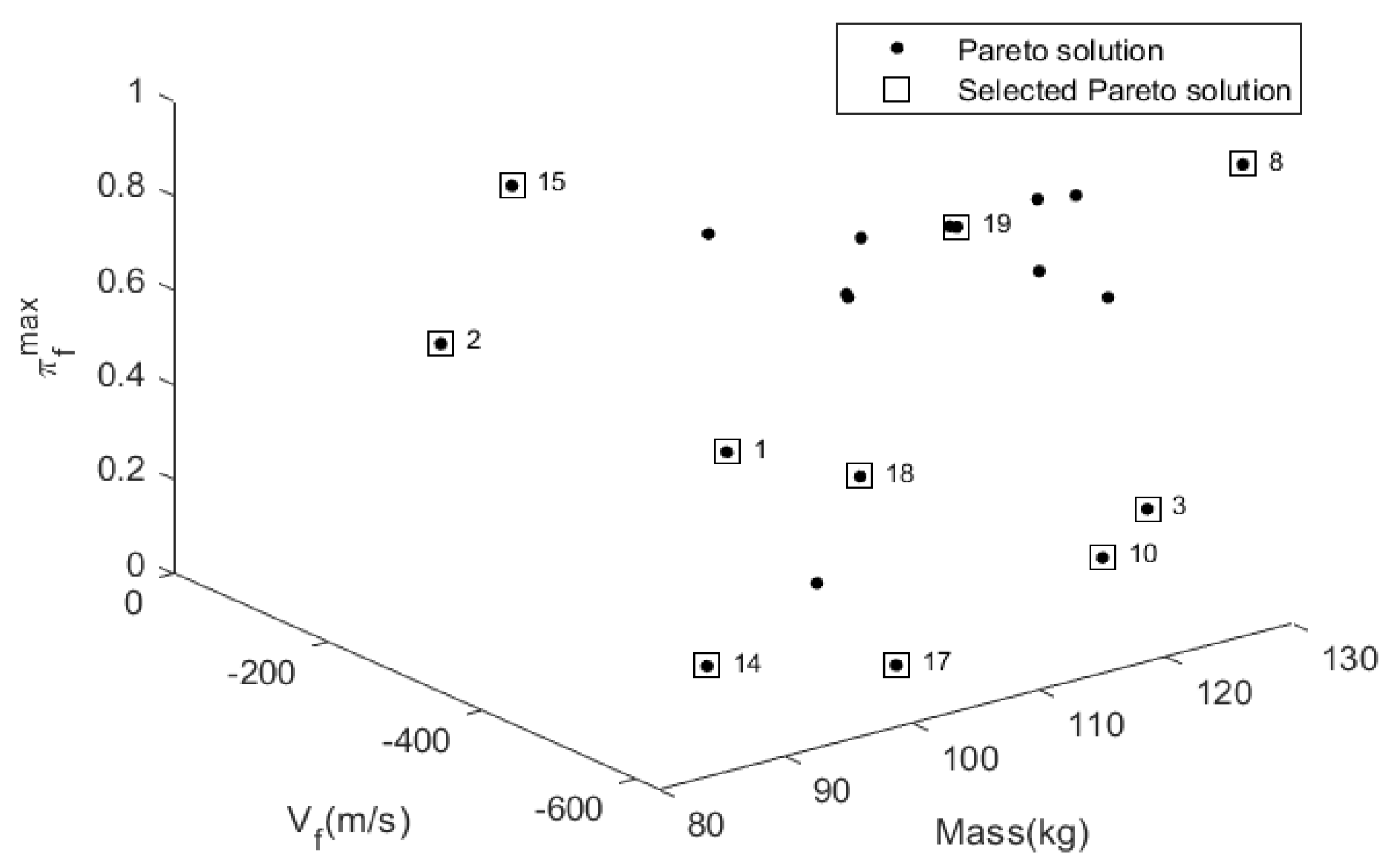
5. Results and Discussion
6. Conclusions
Author Contributions
Funding
Institutional Review Board Statement
Informed Consent Statement
Data Availability Statement
Acknowledgments
Conflicts of Interest
References
- Grihon, S.; Krog, L.; Tucker, A.; Hertel, K. A380 weight savings using numerical structural optimization. In Proceedings of the 20th AAAF Colloquium on Material for Aerospace Applications, Paris, France, 9–12 November 2004; pp. 763–766. [Google Scholar]
- Krog, L.; Tucker, A.; Kemp, M.; Boyd, R. Topology optimization of aircraft wing box ribs. In Proceedings of the 10th AIAA/ISSMO Multidisciplinary Analysis and Optimization Conference, New York, NY, USA, 30 August–1 September 2004. [Google Scholar]
- Wang, Q.; Lu, Z.; Zhou, C. New topology optimization method for wing leading-edge ribs. AIAA J. 2011, 48, 1741–1748. [Google Scholar] [CrossRef]
- López, C.; Baldomir, A.; Hernández, S. Deterministic versus reliability-based topology optimization of aeronautical structures. Struct. Multidiscip. Optim. 2017, 53, 907–921. [Google Scholar] [CrossRef]
- Saitou, K.; Izui, K.; Nishiwaki, S.; Papalambros, P.A. Survey of structural optimization in mechanical product development. Trans. ASME 2005, 5, 214–226. [Google Scholar] [CrossRef]
- Rothwell, A. Multi-level optimization of aircraft shell structures. Thin-Walled Struct. 1991, 11, 85–103. [Google Scholar] [CrossRef] [Green Version]
- Lencus, A.; Querin, O.M.; Steven, G.P.; Xie, Y.M. Aircraft wing design automation with ESO and GESO. Int. J. Veh. Des. 2001, 28, 98–111. [Google Scholar] [CrossRef]
- Harzen, L.U.; Peter, H. Multilevel optimization in aircraft structuraldesign evaluation. Comput. Struct. 2008, 86, 104–118. [Google Scholar]
- Sleesongsom, S.; Bureerat, S. New conceptual design of aeroelastic wing structures by multiobjective optimization. Eng. Optim. 2013, 45, 107–122. [Google Scholar] [CrossRef]
- Bendsøe, M.; Sigmund, O. Topology Optimization; Springer: Berlin/Heidelberg, Germany, 2003. [Google Scholar]
- Saggere, L.; Kota, S. Static shape control of smart structures usingcompliant mechanisms. AIAA J. 1999, 37, 572–578. [Google Scholar] [CrossRef]
- Sleesongsom, S.; Bureerat, S. Aircraft morphing wing design by using partial topology optimization. Struct Multidisc. Optim. 2013, 48, 1109–1128. [Google Scholar] [CrossRef]
- Sleesongsom, S.; Bureerat, S. Morphing Wing Structural Optimization Using Opposite-Based Population-Based Incremental Learning and Multigrid Ground Elements. Mathl. Probl. Eng. 2015, 2015, 730626. [Google Scholar] [CrossRef] [Green Version]
- Meng, L.; Zhang, W.; Quan, D.; Shi, G.; Tang, L.; Hou, Y.; Breitkopf, P.; Zhu, J.; Gao, T. From topology optimization design to additive manufacturing: Today’s success and tomorrow’s roadmap. Arch. Comput. Methods Eng. 2020, 27, 805–830. [Google Scholar] [CrossRef]
- Stanford, B.; Dunning, P. Optimal Topology of Aircraft Rib and Spar Structures Under Aeroelastic Loads. J. Aircr. 2015, 52, 1298–1311. [Google Scholar] [CrossRef] [Green Version]
- Stanford, B. Aeroelastic Wingbox stiffener topology optimization. J. Aircr. 2018, 55, 1244–1251. [Google Scholar] [CrossRef]
- Stanford, B.; Beran, B.; Bhatia, M. Aeroelastic Topology Optimization of Blade-Stiffened Panels. J. Aircr. 2014, 51, 938–944. [Google Scholar] [CrossRef] [Green Version]
- Maute, K.; Allen, M. Conceptual design of aeroelastic structures by topology optimization. Struct. Multidiscip. Optim. 2004, 27, 27–42. [Google Scholar] [CrossRef]
- Towsend, S.; Kim, H. A level set topology optimization method for the buckling of shell structures. Struct. Multidiscip. Optim. 2019, 60, 1783–1800. [Google Scholar] [CrossRef] [Green Version]
- Gomes, P.; Palacios, R. Aerostructural topology optimization using high fidelity modeling. Struct. Multidisc. Optim. 2022, 65, 137. [Google Scholar] [CrossRef]
- Wang, X.; Zhang, S.; Wan, Z.; Wang, Z. Aeroelastic Topology Optimization of Wing Structure Based on Moving Boundary Meshfree Method. Symmetry 2022, 14, 1154. [Google Scholar] [CrossRef]
- Oliveira, É.; Sohouli, A.; Afonso, F.; da Silva, R.G.A.; Suleman, A. Dynamic Scaling of a Wing Structure Model Using Topology Optimization. Machines 2022, 10, 374. [Google Scholar] [CrossRef]
- Thel, S.; Hahn, D.; Haupt, M.; Heimbs, S. A passive load alleviation aircraft wing: Topology optimization for maximizing nonlinear bending–torsion coupling. Struct. Multidisc. Optim. 2022, 65, 155. [Google Scholar] [CrossRef]
- Yang, W.; Yue, Z.; Li, L.; Wang, P. Aircraft wing structural design optimization based on automated finite element modelling and ground structure approach. Eng. Optim. 2016, 48, 94–114. [Google Scholar] [CrossRef]
- López, C.; Baldomir, A.; Hern’andez, S. The relevance of reliability-based topology optimization in early deign stages of aircraft structures. Struct. Multidiscip. Optim. 2017, 55, 1121–1141. [Google Scholar] [CrossRef]
- D’Ippolito, R.; Donders, S.; Hack, M.; Van Der Linden, G.; Vandepitte, D. Reliability-based design optimization of composite and steel aerospace structures. In Proceedings of the 47th AIAA/ASME/ASCE/AHS/ASC Structures, Structural Dynamics and Materials Conference, Newport, RI, USA, 1–4 May 2006; pp. 6621–6633. [Google Scholar]
- Elishakoff, I.; Colombi, P. Combination of probabilistic and convex models of uncertainty when scare knowledge is present on acoustic excitation parameters. Conput. Method Appl. M 1993, 104, 187–209. [Google Scholar] [CrossRef]
- Manan, A.; Cooper, J. Design of composite wings including uncertainties: A probabilistic approach. J. Aircr. 2009, 46, 601–607. [Google Scholar] [CrossRef]
- Scarth, C.; Cooper, J.E.; Weaver, P.M.; Silva, G.H.C. Uncertainty quantification of aeroelastic stability of composite plate wings using lamination parameters. Comput. Struct. 2014, 116, 84–93. [Google Scholar] [CrossRef]
- Scarth, C.; Cooper, J.E. Reliability-based aeroelastic design of composite plate wings using a stability margin. Struct. Multidiscip. Optim. 2018, 57, 695–1709. [Google Scholar] [CrossRef] [Green Version]
- Papageorgiou, A.; Tarkian, M.; Amadori, K.; Ölvander, J. Multidisciplinary design optimization of aerial vehicles: A review of recent advancements. Int. J. Aerosp. Eng. 2018, 2018, 4258020. [Google Scholar] [CrossRef] [Green Version]
- Helton, J.C.; Davis, F.J. Latin hypercube sampling and the propagation of uncertainty in analyses of complex systems. Reliab. Eng. Syst. Saf. 2003, 81, 23–69. [Google Scholar] [CrossRef] [Green Version]
- Pholdee, N.; Bureerat, S. An efficient optimum latin hypercube sampling technique based on sequencing optimisation using simulated annealing. Int. J. Syst. Sci. 2015, 46, 1780–1789. [Google Scholar] [CrossRef]
- Wansaseub, K.; Sleesongsom, S.; Panagant, N.; Pholdee, N.; Bureerat, S. Surrogate-Assisted Reliability Optimisation of an Aircraft Wing with Static and Dynamic Aeroelastic Constraints. Int. J. Aeronaut. Space Sci. 2020, 21, 723–732. [Google Scholar] [CrossRef]
- Fang, J.; Smith, S.M.; Elishakoff, I. Combination of anti-optimization and fuzzy-set-based analyses for structural optimization under uncertainty. Math Probl. Eng. 1998, 4, 187–200. [Google Scholar] [CrossRef]
- Moller, B.; Graf, W.; Beer, M. Fuzzy structural analysis using α-level optimization. Comput. Mech. 2000, 26, 547–565. [Google Scholar] [CrossRef]
- Tang, Z.C.; Lu, Z.Z.; Hu, J.X. An efficient approach for design optimization of structures involving fuzzy variables. Fuzzy Set Syst. 2014, 255, 52–73. [Google Scholar] [CrossRef]
- Yin, H.; Yu, D.; Xia, R. Reliability-based topology optimization for structures using fuzzy set model. Comput. Method Appl. M 2018, 333, 197–217. [Google Scholar] [CrossRef]
- Sleesongsom, S.; Yooyen, S.; Prapamonthon, P.; Bureerat, S. Reliability-based Design Optimization of Classical Wing Aeroelasticity. IOP Conf. Ser. Mater. Sci. Eng. 2020, 886, 012015. [Google Scholar] [CrossRef]
- Sleesongsom, S.; Bureerat, S. Multi-objective reliability-based topology Optimization of Structures Using a Fuzzy Set Model. J. Mech. Sci. Technol. 2020, 34, 3973–3980. [Google Scholar] [CrossRef]
- Sleesongsom, S.; Bureerat, S. Multi-objective, reliability-based design optimization of a steering linkage. Appl. Sci. 2020, 10, 5748. [Google Scholar] [CrossRef]
- Zheng, J.; Luo, Z.; Jiang, C.; Ni, B.; Wu, J. Non-probabilistic reliability-based topology optimization with multidimensional parallelepiped convex model. Struct. Multidisc. Optim. 2018, 57, 2205–2221. [Google Scholar] [CrossRef]
- Xia, H.; Qiu, Z. Non-probabilistic reliability-based topology optimization (NRBTO) of continuum structures with displacement constraints via single-loop strategy. Struct. Multidisc. Optim. 2022, 65, 166. [Google Scholar] [CrossRef]
- Wang, L.; Lui, G.; Qiu, Z. Review: Recent Developments in the Uncertainty-Based Aero-Structural Design Optimization for Aerospace Vehicles. J. Harbin Inst. Technol. 2018, 25, 1–15. [Google Scholar]
- Winyangkul, S.; Sleesongsom, S.; Bureerat, S. Reliability-based design of an aircraft wing using a fuzzy-based metaheuristic. Appl. Sci. 2021, 11, 6463. [Google Scholar] [CrossRef]
- Sleesongsom, S.; Winyangkul, S.; Bureerat, S. Multiobjective reliability-based design of an aircraft wing using a fuzzy-based metaheuristic. In Proceedings of the ASME 2021 International Mechanical Engineering Congress and Exposition, Volume 13: Safety Engineering, Risk, and Reliability Analysis, Research Posters, Virtual, 1–5 November 2021; V013T14A016. ASME: New York, NY, USA, 2021. [Google Scholar]
- Sleesongsom, S.; Kumar, S.; Bureerat, S. Two-Step Multi-Objective Reliability-Based Design Optimization of Aircraft Wing Structures. Symmetry 2022, 14, 2125. [Google Scholar] [CrossRef]
- Chanu, S.; Wattanathorn, A.; Senpong, M.; Sleesongsom, S. Reliability-Based Design Optimization of a Goland Wing with a Two-Step Approach. In: Tan, Y., Shi, Y., Niu, B. (eds) Advances in Swarm Intelligence. ICSI 2022. Lect. Notes Comput. Sci. 2022, 13345, 399–410. [Google Scholar]
- Wansasueb, K.; Bureerat, S.; Kumar, S. Ensemble of four metaheuristic using a weighted sum technique for aircraft wing design. Eng. Appl. Sci. Res. 2021, 48, 385–396. [Google Scholar]
- Winyangkul, S.; Wansaseub, K.; Sleesongsom, S.; Panagant, N.; Kumar, S.; Bureerat, S.; Pholdee, N. Ground Structures-Based Topology Optimization of a Morphing Wing Using a Metaheuristic Algorithm. Metals 2021, 11, 1311. [Google Scholar] [CrossRef]
- Tejani, G.G.; Kumar, S.; Gandomi, A.H. Multi-objective heat transfer search algorithm for truss optimization. Eng. Comput. 2021, 37, 641–662. [Google Scholar] [CrossRef]
- Kumar, S.; Jangir, P.; Tejani, G.G.; Premkumar, M. A Decomposition based Multi-Objective Heat Transfer Search algorithm for structure optimization. Knowl. Based Syst. 2022, 253, 109591. [Google Scholar] [CrossRef]
- Kumar, S.; Tejani, G.G.; Pholdee, N.; Bureerat, S. Performance enhancement of meta-heuristics through random mutation and simulated annealing-based selection for concurrent topology and sizing optimization of truss structures. Soft Comput. 2022, 26, 5661–5683. [Google Scholar] [CrossRef]
- Hosseini Dehshiri, S.J.; Amiri, M.; Olfat, L.; Pishvaee, M.S. Multi-objective closed-loop supply chain network design: A novel robust stochastic, possibilistic, and flexible approach. Expert Syst. Appl. 2022, 206, 117807. [Google Scholar] [CrossRef]
- Habib, M.S.; Omair, M.; Ramzan, M.B.; Chaudhary, T.N.; Farooq, M.; Sarkar, B. A robust possibilistic flexible programming approach towards a resilient and cost-efficient biodiesel supply chain network. J. Clean. Prod. 2022, 366, 132752. [Google Scholar] [CrossRef]
- Abusaq, Z.; Habib, M.S.; Shehzad, A.; Kanan, M.; Assaf, R. A Flexible Robust Possibilistic Programming Approach toward Wood Pellets Supply Chain Network Design. Mathematics 2022, 10, 3657. [Google Scholar] [CrossRef]
- Amoozgar, M.R.; Ajaj, R.M.; Cooper, J.E. The effect of elastic couplings and material uncertainties on the flutter of composite high aspect ratio wings. J. Fluids Struct. 2022, 108, 103439. [Google Scholar] [CrossRef]


| ALUMINUM | ||
|---|---|---|
| Properties | Value | Unit |
| Young’s modulus (E) | 70 × 109 | Pa |
| Poisson’s ratio (ν) | 0.3 | - |
| Density (ρ) | 2700 | kg/m3 |
| CARBON FIBER | ||
| Young’s modulus (E11) | 207.7 × 10⁹ | Pa |
| Young’s modulus (E22) | 7.6 × 10⁹ | Pa |
| Shear modulus (G12) | 5.0 × 10⁹ | Pa |
| Shear modulus (G13) | 5.0 × 10⁹ | Pa |
| Shear modulus (G23) | 5.0 × 10⁹ | Pa |
| Poisson’s ratio (ν12) | 0.3 | - |
| Density (ρ) | 1800 | kg/m3 |
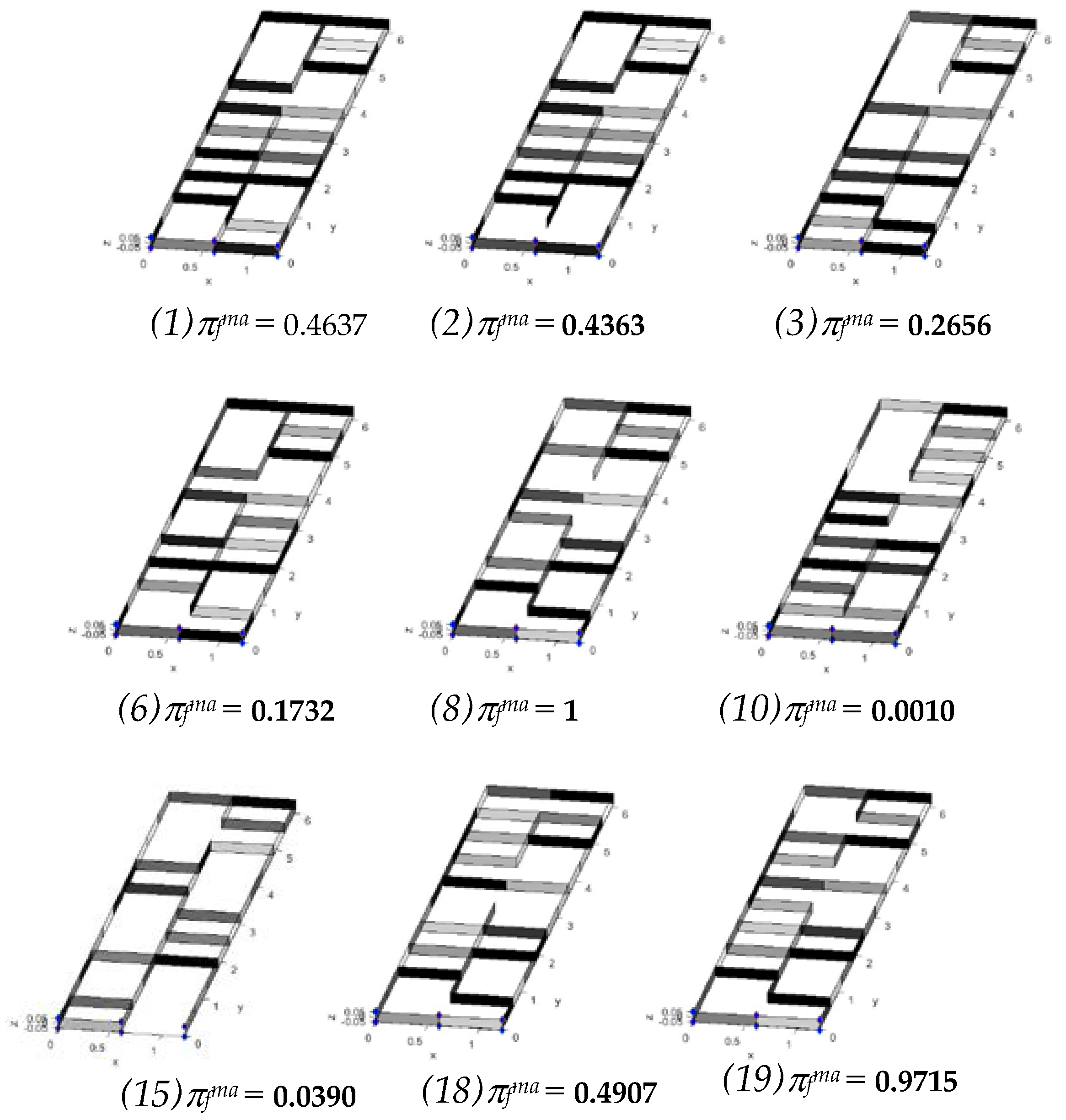
| Sol. No. | πfmax | Mass (kg) | Vf (m/s) | η | umax (m) |
|---|---|---|---|---|---|
| 1 | 0.4637 | 96.5727 | 446.6991 | 1.0636 | 0.0945 |
| 2 | 0.4363 | 95.9038 | 85.5474 | 1.0598 | 0.0949 |
| 3 | 0.2656 | 121.5729 | 581.5058 | 0.9614 | 0.0948 |
| 6 | 0.1732 | 101.7567 | 478.5590 | 1.0566 | 0.0965 |
| 8 | 1 | 126.0044 | 632.7823 | 1.0059 | 0.0435 |
| 10 | 0.0010 | 127.8439 | 419.6791 | 1.0458 | 0.0997 |
| 15 | 0.0390 | 89.3820 | 285.6084 | 1.0628 | 0.0885 |
| 18 | 0.4907 | 99.0811 | 578.8716 | 1.0032 | 0.0906 |
| 19 | 0.9715 | 106.3554 | 584.9849 | 1.0375 | 0.0808 |
| Design Variables and Objective Function | πfmax = 0.9715 (sol.19) | πfmax = 0.4637 (sol.1) | πfmax = 0.001 (sol.10) | Deterministic (sol.8) |
|---|---|---|---|---|
| Upper skin layer 1 (mm.) | 0.0045 | 0.0005 | 0.0040 | 0.0045 |
| Upper skin layer 2 (mm.) | 0.0025 | 0.0030 | 0.0030 | 0.0025 |
| Upper skin layer 3 (mm.) | 0.0010 | 0.0015 | 0.0005 | 0.0010 |
| Lower skin layer 1 (mm.) | 0.0005 | 0.0010 | 0.0050 | 0.0015 |
| Lower skin layer 2 (mm.) | 0.0010 | 0.0005 | 0.0005 | 0.0005 |
| Lower skin layer 3 (mm.) | 0.0035 | 0.0040 | 0.0005 | 0.0020 |
| Lower skin layer 1 (deg.) | 135 | 165 | 135 | 60 |
| Lower skin layer 2 (deg.) | 15 | 15 | 0 | 15 |
| Lower skin layer 3 (deg.) | 105 | 120 | 105 | 105 |
| Upper skin layer 1 (deg.) | 105 | 105 | 120 | 105 |
| Upper skin layer 2 (deg.) | 105 | 105 | 165 | 105 |
| Upper skin layer 3 (deg.) | 165 | 165 | 165 | 165 |
Disclaimer/Publisher’s Note: The statements, opinions and data contained in all publications are solely those of the individual author(s) and contributor(s) and not of MDPI and/or the editor(s). MDPI and/or the editor(s) disclaim responsibility for any injury to people or property resulting from any ideas, methods, instructions or products referred to in the content. |
© 2023 by the authors. Licensee MDPI, Basel, Switzerland. This article is an open access article distributed under the terms and conditions of the Creative Commons Attribution (CC BY) license (https://creativecommons.org/licenses/by/4.0/).
Share and Cite
Sleesongsom, S.; Kumar, S.; Bureerat, S. Multi-Objective Reliability-Based Partial Topology Optimization of a Composite Aircraft Wing. Symmetry 2023, 15, 305. https://doi.org/10.3390/sym15020305
Sleesongsom S, Kumar S, Bureerat S. Multi-Objective Reliability-Based Partial Topology Optimization of a Composite Aircraft Wing. Symmetry. 2023; 15(2):305. https://doi.org/10.3390/sym15020305
Chicago/Turabian StyleSleesongsom, Suwin, Sumit Kumar, and Sujin Bureerat. 2023. "Multi-Objective Reliability-Based Partial Topology Optimization of a Composite Aircraft Wing" Symmetry 15, no. 2: 305. https://doi.org/10.3390/sym15020305