Review

Wire-Grid and Sparse MoM Antennas: Past Evolution, Present Implementation, and Future Possibilities

Department of Television and Control, Tomsk State University of Control Systems and Radioelectronics, 634050 Tomsk, Russia
*
Author to whom correspondence should be addressed.
Symmetry 2023, 15(2), 378; https://doi.org/10.3390/sym15020378
Submission received: 31 December 2022 / Revised: 23 January 2023 / Accepted: 27 January 2023 / Published: 31 January 2023
(This article belongs to the Section Physics)

Abstract

:
Since the end of the 19th century, radioelectronic devices (REDs) have actively penetrated into all modern community spheres. Achievements in the fields of radio engineering and electronics, as well as computing, information, telecommunications, and other technologies, have greatly contributed to this. The main elements of REDs are antennas and microwave devices. For example, linear (wire) antennas are the basis of long-distance communication agency networks of various law enforcement agencies and departments. The manufacturing of REDs requires the regular and rapid appearance of more and more advanced types with minimal costs. At the same time, the design complexity of REDs and the tightening of EMC requirements caused by the growth of upper frequencies of useful and interfering signals, the mounting density, as well as the capabilities of generators of intentional electromagnetic impacts, together with the need to take into account inter-element, inter-unit, and inter-system interference, require more and more accurate designs of REDs. However, this becomes impossible without computer modeling, which saves the time and financial resources required for their development, as well as to evaluate the correctness of the proposed technical solutions. During the design process, as a rule, a multivariate analysis or optimization of the product is performed. In this case, methods of computational electrodynamics (one of which is the method of moments) are used. They are based on the replacement of continuous functions with their discrete analogues (construction of a grid), which reduces the problem to the solution of a system of linear algebraic equations (SLAE). The problem’s complexity depends on the complexity of the SLAE solution, which is determined by its order (which in turn is determined by the complexity of the simulated object and its surrounding area) and by the number of the required SLAE solutions for each problem (determined by the upper frequency of the signal, the number, and range of the optimized parameters). This dramatically increases the computational cost, which becomes the main constraint for the optimal design. Therefore, reducing the computational cost for the analysis and optimization of RED elements (in particular, linear antennas) is an important scientific problem. Meanwhile, finding new antenna structures that meet all the desired features (low price, required characteristics, manufacturable design with small dimensions and windage, etc.) is no less important today. One of the promise solutions for these problems is using a wire grid and sparse antennas for modeling and constructing antennas. Since the last century, a lot of research has been performed on them. The aim of this paper is to review their history and the main related aspects such as computational, acceleration, and optimization used methods, the fields of their application, and their evolution to this moment. In addition, this paper provides a possible future implementation of wire-grid and sparse antennas from the authors’ point of view by presenting a new method that is under research to obtain effective wire sparse antennas.

1. Introduction

One current important trend in electronic technology is to take into account more rigorous system requirements in both commercial and military sectors while maintaining low manufacturing, operating, and maintenance costs. For example, the development of a system capable of working in real time through a special virtual network is relevant to the military sector. Moreover, designing antennas for both ground and onboard subsystems is a unique challenge, as they must be as simple and inexpensive as possible, while at the same time satisfying specific radiotechnical requirements. On the other hand, in the commercial sector, the development of wireless internet access systems, 5G wireless technologies, and the internet of things has led the market to develop low-cost antennas that meet bandwidth, gain, multiband performance, and physical constraints. These trends have prompted developers to create new methodologies and approaches to antenna design. After a long period of separate development of computer-aided design (CAD) systems for antennas and optimization methods, the most promising approach that allows for the identification of design problems and the construction of an optimal structure is the combined use of full-wave electromagnetic modeling and optimization methods. Specifically, the analysis of microwave integrated circuits and printed antennas can be time-consuming, which can lead to a highly inefficient design procedure that typically requires circuit analysis at every iteration of the design cycle, which in turn requires computationally efficient CAD. Thus, it is relevant to develop new methods for synthesizing antenna structures not only to optimize some geometric or physical variables, but also to create the shapes of the structures. These methods should allow for designing an optimal structure that satisfies all the requirements and constraints.
Every decade or so, researchers try to review all the developments and advances in any scientific field. In our time, considerable reviews have been undertaken on modeling and manufacturing antennas and their technologies [1], especially on reconfigurable [2], smart [3], and wearable [4] antennas. In general, these reviews have a narrow focus. For example, this work has been undertaken on beam steering characteristics [5], liquid-based [6], microstrip [7], and switching technology [8] of reconfigurable, meta-wearable [9], smart [10], and transparent [11] antennas. In addition, some studies have been devoted to the design of these antennas where the state of art in designing MIMO [12], 5G [13], and even smart [14] and reconfigurable [15,16] antennas is presented and provides a good database for any interested researcher in this field. However, a general overview of these studies is also helpful, Especially for new researchers. On the other hand, a huge amount of research has been undertaken on modeling antennas, especially those related to modeling wire grid and sparse antennas. Of particular interest are those studies that have used MoM in the past [17,18,19,20,21,22] and today [23,24,25,26,27,28], and even those that use other computational methods [29,30,31]. However, as we know, there exists no extensive general review on modeling wire-grid and sparse antennas using MoM. Therefore, the aim of this paper is to review the issues on modeling antennas using MoM and the main related aspects such as the computational, acceleration, and optimization-employed methods and the fields of their application. In addition, this paper aims to provide a possible future implementation of wire-grid and sparse antennas from the authors’ point of view by presenting a new under research method to obtain effective wire sparse antennas.
This paper is organized as follows. In the second section we concentrate on MoM and review the studies of other researchers related to this method and other computational methods. We try to reflect the reasons behind the relevance of investigating MoM. We also provide a considerable amount of research related to the use of MoM and the methods employed to accelerate the modeling and calculating process. In addition, we mention some of the hybridization approaches that used MoM in combination with other methods. In addition, we review some research that contains remarkable experience on using MoM for modeling antennas. In the third section, and as one of the most important aspects when modeling antennas, our review focuses on optimization methods, especially genetic algorithms (GA), and the works that combined MoM and GA when modeling antennas. In the fourth section, we provide a review of reconfigurable and smart antennas, followed by a review in the fifth section of wire-grid sparse antennas, which are important to us. We also present a new method that can be used both for creating and modeling antennas and scatterers and demonstrate its capabilities. This method can be used for manufacturing a sparse wire-grid antenna. The main idea is to avoid using wires with low currents in the antenna grid, since their contribution to radiation is small.

2. Why MoM?

2.1. Overview of Computional Methods

In the past, methods were developed to efficiently solve general electromagnetic (EM) problems, which were based on either differential or integral equations. The resulting systems of linear equations are solved either by direct methods or iteratively. The development of computer technology, combined with the development of fast algorithms with reduced computational complexity and memory requirements, has made it possible to accurately solve problems of electrically large objects numerically. These numerical methods are based on solving partial differential equations (e.g., using the finite difference method [FDM] or finite element method [FEM]) that are reduced to sparse matrices, or solving integral equations that are converted to dense matrix equations (e.g., using the method of moments [MoM]). Solving EM problem with N unknown by a direct solver (Gauss elimination) requires computational complexity O(N3) and memory requirements O(N2). However, by correctly ordering the matrix elements, it is possible to effectively compress and solve the corresponding band matrix equation with computational complexity O(N).
The method of conjugate gradients (MCG) [32] is used to solve the Poisson equation. Thus, it converges in O(N0.5) iterations for two-dimensional problems and in O(N0.33) for three-dimensional problems, respectively. When a multigrid method is used to solve the same equation, the number of iterations does not depend on the order of the matrix [33]. As a consequence, the total computational cost associated with the MCG for such problems scales as O(N1,5) for two-dimensional problems and O(N1,33) for three-dimensional problems. For multigrid methods, the total computational cost scales as N.
The finite difference time domain (FDTD) method is one of the most popular methods for solving electrodynamic problems numerically and was first described in [34]. However, the abbreviation of the method’s name was suggested by the author of [35]. The method is based on a procedure deployed in the time domain during which continuous electromagnetic waves are replaced by their discrete analogues [36]. The discrete representation is realized for the space and time included in Maxwell’s equations. This method is a simple and straightforward approach to solving Maxwell’s equations and has an explicit solution scheme that does not require linear algebraic equations (SLAEs) to be stored, as well as an implicit scheme that reduces to a system of SLAEs [37]. Besides, the FDTD method quite simply describes the inhomogeneity of the medium. Working in the time domain allows for results to be obtained in a wide range of frequencies. This method allows the researcher to specify the material at each point of the volume and choose not only from a wide range of metals and dielectrics, but also materials with nonlinear properties. It allows one to directly simulate the effects on the holes as well as the shielding effects, while the fields inside and outside the shield can be calculated either, directly or not. However, this method, like all methods, has disadvantages. First, the counting volume must be divided into a very large number of cells (the subarea [cell] size is small compared to the smallest wavelength), which means large memory and simulation time costs. This makes it difficult to simulate problems with long, thin spatial structures, such as the fields obtained from currents along conductors. Second, the calculation of the fields is performed at each point of the counting volume, so if you want to find the field at a certain distance from the source, it probably means that the counting volume will be excessively large. But it must be finite to fit in the computer’s memory, which in most cases is achieved by setting artificial boundary conditions on the counting volume, the use of which can lead to data distortion. Nevertheless, in the case of using FDTD to solve the wave equation directly in the time domain, the computational complexity is the same as the MCG (N1.5 for the two-dimensional problem and N1.33 for the three-dimensional problem) [38], except that FDTD generates a solution for the entire time domain, and therefore for all frequencies at once. This algorithm is optimal because it generates O(Nx) solutions using O(Nx) operations.
The Finite Element Method (FEM) is widely used in the mechanical analysis of structures. Despite the fact that the mathematical treatment of the method was proposed in 1943 by Courant [39] for solving electromagnetic problems, this method was not applied until 1968. Since then it has been used in the analysis of waveguides, electrical machines, semiconductor devices, multiconductor lines, electromagnetic radiation from biological objects, etc. [40,41,42,43,44,45,46,47]. The general nature of the FEM allows for the building of universal computer programs based on it in order to solve a wide range of problems. Therefore, programs developed to solve problems from other disciplines can be and have been successfully applied to solve problems from another discipline with or without minor modifications [48]. The main idea of FEM is that any continuous value (temperature, pressure, etc.) is approximated by a discrete model that is constructed using a set of piecewise continuous functions defined on a finite number of subdomains [49]. The algorithm for constructing a discrete model of a continuous quantity is as follows. A finite number of points are fixed in the area under consideration. These points are further called nodes. Assume that the studied continuous value at each node is a variable that is to be determined in the process of solving the problem. The region of the continuous value change is divided into elements. These elements have common nodes between them and, together, approximate the shape of the entire region. The continuous value is approximated within each element by a polynomial, the coefficients of which are calculated according to the quantities of this value in the nodes. Each element is approximated by its own polynomial, and the coefficients of the polynomials are chosen so that the continuity of the value along the boundaries of neighboring elements is preserved. Then, the finite elements are combined into an assembly. In this assembly, the nodal quantities of the unknown functions are chosen in such a way that a sufficient approximation of a continuous distribution is achieved. This step leads to a SLAE with respect to the nodal quantities. After that, the resulting system has to be solved, i.e., the nodal quantities must be found. To approximate a continuous region, when solving the formulated boundary problems, a system of pyramidal elements is used that allows writing down a system of equations for E (or H). Their solution determines the interpolation polynomial coefficients. Then the finite elements are combined into an assembly, and the interpolation functions are expressed through global nodal quantities and global coordinates (related to the model as a whole). A sufficiently complete presentation of the method is given in [50,51]. The main advantages of FEM are the clear physical meaning at all stages of the calculation, which allows one to easily control the results, and the simplicity of calculating the characteristics of combined structures that include multiple elements of various sizes. The disadvantages of FEM lie in the need for an efficient finite element generator; the complexity of the equations; the discretization of the occupied region with a variable step, which leads to the increase in the computational cost while forming a volumetric model; and the increase in the computational cost in multicomponent environments. If the FEM nodes are ordered correctly, the dense matrix will appear only in the lower right corner of the system matrix [52,53]. In this way, it is possible to find the inversion of the system matrix using the matrix splitting method. When the nested dissection ordering [54] is applied to the sparse part and the LU-decomposition is applied to the dense part, the total computational complexity is O(N1,5) for two-dimensional problems and O(N2) for three-dimensional ones. The memory requirements are O(NlogN) for two-dimensional and O(N4/3) for three-dimensional problems.
One of the disadvantages of differential equation solvers is the mesh dispersion error that causes the wave to have a different phase velocity within the mesh compared to the exact solution [55,56]. This error can be eliminated by using a higher mesh density but causes an increase in the computational cost. Since the error is cumulative, it is especially noticeable when simulating a large region or in the case of large scatterers. To eliminate this error, the density of the mesh must be increased as the size of the modeling region increases. For second-order precision designs, the mesh density in one dimension (number of points per wavelength) is defined as (kd)0.5, where d is the diameter of the modeling region, and k is the wave number [57]. Consequently, the number of unknowns is (kd)1.5 for one dimension. Correspondingly, for two dimensions the number of unknowns scales as (kd)3, while for three dimensions it scales as (kd)4.5. The solution lies in using an accurate higher-order differential equation solver [58,59] or in combining a differential equation solver with an integral equation solver when there are large homogeneous regions.
Among the existing numerical methods, MoM [60] is one of the most frequently used methods in modeling microwave and millimeter integrated circuits and is widely applied to the problems of electromagnetic compatibility [61]. The name “method of moments” is, according to some authors, unfortunate, because it has a slightly different meaning in modern applied mathematics [62]. However, when solving the problems of electromagnetism, this approach is historically still called MoM. When Harrington chose a name for the method he used, he borrowed it from the work [63] where the authors described a method for solving an integral equation and called it MoM. Earlier, a method with this name was proposed in [64] where polynomials (moments functions) were used as test functions for solving integral equations. However, it should be noted that within Harrington’s paper, he used the term “method of moments” to refer to the method of weighted residuals (MWRs), despite the fact that he limited himself only to linear electromagnetic problems [65]. In the version of MoM proposed by Harrington, piecewise constant (impulse) functions are used as basic functions and Dirac functions as test functions. This is also known as the collocation method. Harrington in [66] made a generalization that allows us to consider the collocation, Galerkin, and least-squares methods as special cases of MoM. According to some authors, FEM and even FDM methods can also be considered as special cases of MoM [67]. In applied mathematics, however, this approach is commonly referred to in another way. Thus, in 1956, the work [68] proposed the term “weighted residuals”, which generalizes a whole family of these methods. A general discussion of this approach can be found in [69,70]. The development of the MWRs is manifested in the works of [66,71,72,73,74,75].

2.2. The Use of MoM

In MoM, the boundary value problem for the unknown current distribution over the conductor surface is often formulated as an integral electric field equation. Then, applying suitable basic and test functions, these equations can be transformed into a SLAE with a dense matrix. The computational complexity of solving a SLAE of order N is O(N3) by the direct method. When modeling millimeter-scale integrated circuits where N is fixed and relatively small, it is sufficient to use a traditional direct method for solving the SLAE. After solving it, circuit characteristics, such as S-parameters, radiation losses, etc., can be obtained from the current distribution. These can be obtained by applying MoM either in the spectral domain [76] or in the spatial domain [77].
Over time, this method has been used and developed considerably. For instance, [78] presents a method based on the Galerkin realization and is closely related to the approach in the spectral domain. The results are a full harmonic/time electromagnetic analysis of the microstrip, which can be used to evaluate individual microstrip inhomogeneities or, on faster computers, the entire microstrip circuit. The proposed approach is quite effective, since the results of the analysis of simple circuits can be obtained in a reasonable period of time, even by using a personal computer. Then, in [79] the authors also used MoM to solve the integral equation for an accurate full-wave analysis of shielded microstrip inhomogeneities, obtained by applying the reciprocity theory. This paper [80] presents the results of full-wave analysis in the spectral domain using the Galerkin method with vector functions of a triangular subarea as expansion and testing functions of the MoM procedure to investigate various microstrip inhomogeneities. This approach proved itself to be a very accurate method for analyzing compensated microstrip inhomogeneities. A grid structure and database for storing impedance matrix elements that can be used to analyze structures of different geometries are demonstrated. MoM is also used in [81] to solve an integral equation reduced to SLAE, expressed in a modified method of spectral analysis proposed by the authors to calculate three-dimensional microwave structures. Based on the realization of MoM in the spatial domain, a full-wave version was developed for analyzing and determining the circuit characteristics of passive microstrip elements (in an open environment) at microwave frequencies [82].

2.3. MoM Acceleration

Computation time and memory requirements are greatly reduced by efficient moment matrix filling, the use of closed-form Green’s functions, and symmetry in the problem formulation; thus, a circuit of moderate electrical size can be analyzed in an acceptable period of time on a personal computer. The solvers of integral equations usually use fewer unknowns than the solvers of differential equations, because in the first case only the induced sources are unknowns, whereas in the latter case the unknown is the field. However, the use of integral equation solvers results in dense matrices [83]. If the matrix equation is solved using the LU-decomposition (Gaussian elimination) or the iterative method (CG or similar methods), the computational cost can be significant [84]. Performing the LU-decomposition requires O(N3) operations and O(N2) memory and provides a solution for all scatterer excitations. The CG method requires O(N2) operations per iteration for dense matrices, since the costliest step in the CG iteration is the multiplication of the matrix by a vector. As a rule, the number of iterations increases as the electrical size of the object increases.
Many researchers have tried to reduce the complexity of the traditional MoM algorithm by reducing the computational cost of the corresponding matrix-vector multiplication. Methods that use matrix operations, such as the order recursive method of moments (ORMoM) proposed in [85] or the fast multipole method (FMM) proposed in [86], reduce the computational cost of matrix multiplication. The impedance matrix localization (IML) method developed by [87] is based on the use of basic functions that lead to a sparse MoM matrix, which, in turn, speeds up the operation of matrix multiplication by a vector. It is worth noting that IML is only suitable for smooth surfaces. Likewise, the complex multipole beam (CMB) method [88] was introduced, which is also applicable only to smooth surfaces. The pseudo-grid algorithm described in [89] has been used to develop a mixed potential integral equation method in the spatial domain. This method, which may be used to analyze microstrip inhomogeneities and antennas of arbitrary shape, is derived from applying MoM to the mixed potential integral equation (MPIE) in the spatial domain to find both current and charge distribution on the microstrip surface. The ordered recursive Gaussian elimination (ORGE) method [90] effectively exploits the data overlap that occurs when designing and optimizing millimeter-wave integrated circuits (MMICs) using MoM, because multiple subtasks involving dimensional changes in different parts of the circuit must be iteratively modeled, which leads to significant data overlap among these subtasks since each subtask is solved independently of the others, without regard to data overlap. Later, researchers proposed the direct matrix manipulation (DMM) in [91] and methods based on wavelets [92], then in [93] they proposed a multistructure MoM technique based on simultaneous analysis of different structures. In practice, all structures under study are derived from the same global structure, and solutions of derived problems are obtained by simple analytical manipulations performed on the solution of the global structure. This concept avoids a large number of repetitive calculations and therefore dramatically reduces the computation time. Unlike most other fast methods, this method does not rely on simplifying assumptions but simply reuses the available information for further calculations. As a result, the proposed simultaneous simulation provides exactly the same accuracy as the equivalent individual simulation. Meanwhile, the computer requirements are significantly reduced.
The work on reducing the modeling time is mainly related to obtaining an approximation of the original matrix with acceptable accuracy. This approximation is used to speed up the iterative solution by substituting the original matrix with the approximated one. The main results on the theory of dense matrix approximation were obtained by the research group of E. Tyrtyshnikov. During the work under the grant RNF 14-11-00806 (2014–2016), the authors, in particular, investigated the application of algebraic methods of approximation of large dense matrices to increase the computational efficiency of methods for solving integral equations of mathematical physics. Moreover, in the work [94], the researchers developed and implemented algorithms for constructing mosaic-skeleton approximations, the iterative method of GMRES in relation to the solution of SLAEs with an unchanged matrix in mosaic-skeleton format and several right-hand sides. The developed algorithms are applied to solving problems of scattering of electromagnetic waves on ideally conducting surfaces of complex shape.
Ilyin’s works are devoted to the solution of very large sparse SLAEs obtained by approximating the boundary value problem by means of a finite-volume exponential scheme, with the help of new methods under development such as the method of bisconjugate residuals, the dual method of bisconjugate residuals, and the stabilized method of bisconjugate residuals. Thus, the work [95] considers a set of algorithmic and technological problems related to the development, research, and application of high-performance parallel methods for solving large SLAEs with sparse matrices. A number of the presented original results are related to the development of iterative processes in the Krylov subspaces, as well as principles of their preconditioning and scalable parallelization based on additive domain decomposition algorithms. The concept of the Krylov library is described as integrated open software for a wide range of linear algebra problems.
There are ideas of developing iterative methods for solving sparse SLAEs [96,97] and employing the approximation of the original dense matrix, not only to reduce the required memory size, but also to speed up the iterative process by using the approximated matrix as a preconditioner. The main results of improving on E. Tyrtyshnikov’s ideas were obtained by S. Rjasanov and M. Bebendorf [98]. In work [99], the method of moments in the frequency domain was applied to model electrically large problems. To speed up the computations, a parallel version of LU decomposition was used, and the unknowns were grouped into blocks that were approximated by matrices of small rank using adaptive cross-approximation. The proposed method was tested on problems with the number of unknowns reaching four million.
In the work [100], two block iterative methods for solving sparse SLAEs obtained by finite difference and element methods were proposed. Their computational costs for solving SLAEs with a constant matrix and several right-hand sides were considered. The effectiveness of the proposed methods was demonstrated by the example of electromagnetic analysis of two test three-dimensional structures. It as shown that when using an effective preconditioner, it is preferable to use block methods to sequentially solve all SLAEs with different vectors of free terms. In the work [101], new methods for solving a number of SLAEs with a shift (with matrices differing from the original matrix by a scalar multiplied by a unit matrix) and many right-hand sides were proposed.

2.4. MoM Hybridization

Each method is applied to the problem region for which it is best suited. The appropriate boundary conditions are applied at the borders between these regions. The method of boundary integral equations is used in combination with MoM to determine, based on the analysis of frequency-dependent lossless and lossy propagation, the characteristics of open multiconductor transmission lines in multilayer media [102]. A complete procedure for optimizing microwave and millimeter-wave planar circuits using MoM is presented in [103]. In this procedure, a new concept of electromagnetic optimization using MoM was proposed. It is based on the study of the smallest independent units of information, the so-called elementary invariant operands.
None of the numerical methods are suitable for all required electromagnetic modeling problems. For example, MoM program codes are practically unsuitable for describing inhomogeneous nonlinear dielectrics. Finite element codes cannot effectively model large scattering problems. Multipole and diffraction-based approaches are not suitable for small complex geometries or problems that require accurate determination of the surface current. Unfortunately, there are tasks where all these features must be taken into account, for example, when evaluating radiation from a printed circuit board, and therefore, the analysis cannot be performed by any of these methods. There are some hyper-methods that result from combining MoM with other methods. One of the solutions is to combine two or more methods in one program code. Moreover, one of these methods is often MoM. For example, a hybrid method, which combines two numerical methods: the finite-difference formulation of alternating-direction implicit (ADI) in the time domain (ADI-FDTD) and the method of moments in the time domain (MoMTD), was proposed to simulate a short-pulse ground-penetrating radar (GPR) [104]. Another hybrid method based on the equivalence principle is presented in [105]. Additionally, the work describes the problem of antennas located on the ground. This problem has been split into two related equivalent problems: one for the antenna geometry and one for the ground geometry. The fields in each region can be modeled using the most appropriate numerical methods. FDM in the time domain was used for modeling the surroundings because it is well suited for modeling fields in inhomogeneous media, while MoM was used for antennas because it is well suited for modeling complex antennas in free space. The same hybrid approach (the combination of MoM and FDM in the time domain) was also applied to estimate the specific absorption ratio (SAR) of a rat inside a reverberation chamber (RC) [106]. This hybrid approach was an alternative method used to solve the problem of poor FDM convergence when analyzing the RC. Initially, RC with a dipole or helical antenna was numerically designed to operate at a frequency of 2 GHz. The MoM/FDM method was then used to calculate the average whole-body SAR (WBA-SAR) of a small animal inside the chamber case. The results were compared with those obtained using the FDM method to verify their accuracy. The combined MoM/FDM approach was also used to analyze the effects of millimeter waves on a rabbit’s eye, using a dielectric lens antenna as the source of electromagnetic emission [107]. MoM was used and validated by comparing the calculated and measured electric fields emitted by the dielectric lens antenna. The hybrid method was then used to determine the specific absorption coefficient of the impact of millimeter waves on the eye of a rabbit placed in the focus of the antenna. In 2007, a highly efficient computational method based on a hybrid formulation of the physical optics moment method (MM-PO) combined with impedance matrix interpolation and dynamic adaptive frequency discretization was presented for broadband analysis of antennas radiating in the presence of conducting objects [108]. The author then used this technique for broadband analysis of antennas radiating in the presence of electrically large conducting bodies (platforms). The results of using this method are presented, and they showed significant savings of both computer memory and CPU time [109]. In 2011, MoM was comprehensively hybridized with other methods (e.g., FEM, PO, or UTD) and accelerated with the multilevel fast multipole method (MLFMM) [110]. A technique for combining the FEM solution for volume electric fields and MoM (or boundary integral solutions for the cut-off boundary) to solve open boundary problems was presented in [111]. This technique was based on a highly parallelized domain decomposition infrastructure.

2.5. MoM Antennas

Historically, MoM has been developed very intensively in relation to the problems of electrostatic and electrodynamic analysis of wire structures [112,113]. Their analysis is an important task because they are used as antennas [114,115,116,117,118] in grounding and equipotential bonding systems, in surface approximation [119,120], and in the development of various electromagnetic field simulators [121]. The analysis of linear (wire) antennas is reduced to the solution of the integral (integro-differential) Pocklington [122] and Hallen [123] equations. The specific features of the solution of these equations are based on the thin-wire approximation and are discussed in detail in several works, e.g., [124,125,126,127,128]. In this approach, the conductor is assumed to be an ideal conductor in the form of a cylinder located along one of the coordinate axes (one-dimensional problem), with a cross-sectional radius much smaller than the wavelength of the excited signal and the conductor’s physical length. It is also assumed that the current is zero at the ends of the wire. This simplification allows one to use a scalar current density function instead of a vector function, which significantly reduces the complexity of the problem.
The time required to solve the problem became the determining factor in choosing one or another numerical method [129]. In addition, the required machine memory capacity is important, as it allows the use of relatively weak workstations to solve complex problems [100]. The use of methods for solving SLAE is also strictly associated with the peculiarities of storing its matrices [130,131,132]. Reducing the time to form and solve the SLAE to reduce the computational cost of modeling, for example when using MoM, can be achieved by choosing the method of structure discretization, which allows approximating its regions with a smaller number of subdomains, thereby reducing the order of SLAE [133]. In this case, the selection of the sets of basis and test functions most suitable for each specific task is the most important [134]. The choice of basis and test functions, which allow approximating the desired function with a small number of them [135], reduces the time spent on calculations. The choice of similar basis and test functions gives a symmetric matrix [136]. To accelerate MoM, solid-state storage devices (SSDs) [137] and parallel computing on the CPU and/or GPU [138] were also used.
Approximation of the SLAE matrix can be achieved by using iterative methods [139], low-rank approximation of matrices [140], zeroing (discarding) the matrix elements of the generated SLAE, whose values are less than a given threshold, and, consequently, transforming the dense matrix into a sparse one, with its further solution by one of the methods for sparse systems [141]. As a result, a general research trend is the reduction of the time required to calculate with the required accuracy and to obtain an optimal structure.
Currently there is a growing interest in the optimization of electromagnetic devices. As a consequence, significant efforts have been made to develop competitive optimization methods. However, it should be noted that different optimization algorithms may be used for different applications in order to meet the specifications of the problem [142]. It is also worth noting that the geometric shape plays an important role in changing the characteristics of the design. For example, for a patch antenna, the circular polarization characteristic can be obtained either by placing stubs in proper locations or by placing diagonal connectors in the center of the antenna. In addition, the antenna can be tuned using a powered configuration, or the bandwidth can be increased by adding parasitic elements. It is outstanding that for different types of applications, only a small part of the antenna structure is changed; it is either removing from or adding to the structure’s geometry to obtain the desired specification. Consequently, there is no need to solve the entire problem at each iteration in the optimization process. This is because in each iteration step, only a few rows and columns are added or removed from the matrix system used in the previous iteration step. Since this procedure greatly reduces the computation time, it becomes possible to evaluate, in real time, the effects caused by the changes in geometry that are made during the design process to improve system performance.

3. Optimization

3.1. Optimizing Methods

It is very important to choose the optimization algorithm that is best suited to the task being solved. The goal of optimization is to minimize (or maximize) the objective function under certain constraints. Optimization using the directed search approach can be achieved by using an iterative algorithm consisting of two steps. In the first step, the “improvement” direction is determined at the iteration point, followed by a one-dimensional search in which the point of the next iteration is calculated by finding the minimum in the “improvement” direction that was determined earlier. Among different types of directional search algorithms, the most common are the steepest descent (SD), Newton, CG, and quasi-Newton methods [143]. As a rule, SD is the first choice in many applications because of its simplicity and globally convergent behavior. However, in many other applications that require a large number of variables, CG and quasi-Newton methods are preferred, which also globally converge, because of their better performance, especially at the optimal points. The most commonly used one-dimensional search algorithms are the equal interval search, golden ratio search, dichotomous search, Fibonacci search methods, and parabolic fitting method [144]. If a fixed interval of uncertainty with a minimum number of function estimates is required, the Fibonacci search algorithm is the preferred choice. However, the genetic algorithms (GA) [145] and simulated annealing methods [146], which are stochastic rather than deterministic in nature, represent two alternatives to the traditional optimization algorithms. In addition, they use a directed random search to find optimal solutions in complex domains.

3.2. GA

Since traditional optimization algorithms deal with local properties of the iteration points, they may stall at a local extremum. In contrast, GAs use a random search in addition to a systematic search, which prevents these methods from hitting a local minimum or maximum. In fact, it was proved that under certain conditions, Gas converge to the global optimum [147]. Gas are structured to solve real-world problems by simulating processes that occur during natural evolution. The coding mechanism maps each solution as a unique binary string. The set of strings constitutes a population, and it evolves from generation to generation through the use of genetic operations, the most common of which are reproduction, crossover, and mutation [148]. The number of function estimates in one generation depends on the generation base used for optimization. For conventional Gas, determining the population size depends on the specific task and is highly dependent on chromosome length and power [149]. When applying Gas, most of the steps can be performed in different ways, and there are many parameters that require precise tuning. Consequently, it may be necessary to test different combinations of possible parameter choices and possible ways of applying genetic operators in order to achieve the maximum benefit from GA for each task. The concept of the genetic algorithm, first formalized in [150] and extended to functional optimization in [151], involves the use of optimization search strategies modeled after Darwinian notions of natural selection and evolution. Many extensions of and improvements to the simple GA optimizer have been developed and used. Among them are the concepts of elitism [152], the use of steady-state algorithms [153], the use of real coded parameters [154], the concepts of community-based genetic algorithms [155], and approaches applicable to the traveling salesman problem.

3.3. The Use of GA

The application of modern electromagnetic theory to radiation and scattering problems often requires the use of optimization. Among typical problems that require optimization are reflector design [156], object resonance extraction [157], and the development of an anti-reflective coating for a low radar cross section (RCS) [158]. Other tasks, such as the formation of the antenna array radiation pattern [159], which were solved without the use of optimization, are often easier to solve with optimization. This applies, in particular, when dealing with implementation limitations imposed by production considerations or environmental factors, differentiated regions, and/or discontinuous regions. In such situations, approximations or models of true electromagnetic phenomena are often used to save computational resources. These characteristics severely test the capabilities of many traditional optimization methods and often require their hybridization. For example, the use of GAs has become very common because of their special characteristics that make them an ideal tool that combines well with existing EM analysis methods and usually gives satisfying results. GAs are well suited for tasks where one needs to find an optimal solution among a large number of admissible ones. Consequently, in addition to the discreteness of the problem due to the large search space, GAs show good results when applied to this type of optimization problem. GAs are significantly more efficient and provide much faster convergence than random walk algorithms. In addition, they are easy to program and easy to implement. In contrast to gradient search, GA optimizers can easily handle discontinuous and undifferentiated functions.
The use of evolutionary optimization strategies for EM design has also become widespread. Thus, in [160], a new method for optimizing the design of electromagnetic devices that uses GAs as a search method was presented. The method is used to optimize the pole shape of an electric motor. The electromagnetic analysis of the implemented devices is performed using FEM. The paper [161] presents an example of GA used for electromagnetic optimization. This work describes the development of lightweight broadband microwave absorbers, the design of antenna arrays with shaped-beam patterns, and the extraction of resonant modes of radar targets from backscatter response data. In addition, the paper [162] describes the basics of GAs, presents their history regarding their EM applications, describes the application of modern genetic operators to the field of electromagnetism, and presents the design results for various applications. The paper [163] presents a new optimization technique that combines classical and statistical methods in an innovative and efficient way. In particular, an evolutionary GA that uses a local minimization scheme based on the conjugate direction method was developed. The proposed optimizer can be applied to the design of planar microwave circuits and printed antenna arrays. The paper [164] presents the results of experiments to determine the optimal population size and mutation rate for a simple genetic algorithm. It was shown that the use of a small population size and relatively high mutation frequency is much preferable to the large population size and low mutation frequency used in most articles.
The proliferation of wireless communication networks has created a natural interest in network optimization. In particular, the emphasis on low cost in many modern wireless networks often imposes severe limitations on the acceptable level of complexity of the transceiver processing circuitry. The available transmitter power in modern networks is also often high. Therefore, solving the design problem usually requires significant optimization in conjunction with network modeling. Using GAs, the authors in [165] managed to maximize the nodal signal-to-noise ratio (SNR) while minimizing transmitter power levels. The GA approach to adaptive phase zeroing is significantly faster than random search and gradient methods, which was proven in the work [166] and later in [167] as applied to satellite communication antennas. The GA was developed to optimize the number and size of cells for a circular symmetric grid. Moreover, numerical optimization based on GAs has been used to develop multilayer broadband radar absorbers [168]. In [169], a procedure for synthesizing radio-absorbing materials to reduce the radar cross section in the broadband frequency range is presented. GAs have also been widely used to optimize microstrip circuits, as in [170,171].

3.4. Antennas and GA

When designing antennas, there may be a need for a particular desired shape or desired multiband or even multifrequency operation. Optimization methods find application in this important case as well. In 1994, the authors of [172] proposed the use of GA in antenna design. Later in 1996, a deductive antenna design method was proposed to specify the desired electromagnetic properties, resulting in the so-called genetic wire antennas [173]. The authors of [174,175] then developed this approach and applied it to synthesize wire antennas loaded with concentrated components. In 1999, this combination was used to simultaneously control both achievable gain and grating lobe reduction in the optimal synthesis of Luneberg lens antennas in [176,177,178]. In [179], GA was also used to optimize the maximum level of the side lobes of a planar array. Under the same work title, researchers used GA for amplitude and phase adaptive zeroing in [180], and the same has been undertaken later in [181]. The same optimization method was used to design automobile antennas in [182], patch antennas with circular polarization in [183], and uniformly excited broadband low sidelobe linear and planar antenna arrays in [184]. A new application of GAs to design rectangular microstrip antennas was presented in [185,186,187,188,189]. Using FDM and GA, the authors of [190] designed a compact broadband low-profile antenna. In [191], GA was used to synthesize a directional circular arc array pattern to minimize the bit error rate in an indoor wireless communication system. In [192], optimized shapes of multiband microstrip antennas using GA were investigated. For two-, three-, and four-band microstrip shapes, the obtained antennas showed good performance at the design frequencies.

3.5. MoM Antennas and GA

MoM has proved to be the best option among a large number of numerical methods used in combination with one of the optimization methods to improve the matrix-filling procedure and reduce the solution time. Thus, there have been attempts to combine Gas and MoM, for example. In particular, the paper [142] describes the design of compact microwave filters using GA in combination with the 2.5D MoM. In addition, the paper [193] presents the results of applying well-known numerical simulation codes (NEC) and GA to design wire antennas with circular polarization and wide angular coverage. In both cases, the results obtained from GA optimization showed excellent performance for the chosen optimization parameters. The method of creating new shapes for resonant structures is presented in [194]. To analyze the tested structures, the full-wave method in the spectral domain was used. This method effectively uses GA to find new forms of resonant structures. Meanwhile, the authors of [195] demonstrated the possibility of creating new, fully dielectric waveguide grating filters using GA to optimize the dielectric material permittivity and placement of geometric boundaries that separate homogeneous regions. The work [196] describes a technique to effectively combine GA and MoM to design an integrated antenna. This technique was proposed earlier in [197], and it is based on using the direct Z-matrix transformations (DMM) for effective GA and MoM integration. Using DMM with GA/MoM significantly reduces the overall optimization time by eliminating several filling operations on the Z-matrix.
As an extension of an effective numerical method based on the derivation of closed-form Green’s functions and the analytical evaluation of MoM matrix elements, the authors of [198] use the gradient search and GA in combination with electromagnetic simulation methods to evaluate the potential of using this approach as a CAD tool. In the work [199], the application of optimization methods to design ultra-wideband antennas for multifunctional wireless devices is discussed. The antennas investigated in this work are monopoles with flat all-metal radiating elements. In [200], the authors presented a procedure to design broadband microwave radiation absorbers including frequency-selective surface (FSS) screens embedded in a dielectric media, using GA with binary coding or the so-called microgenetic algorithm (MGA). Such a variant of GA simultaneously and optimally selects the material in each layer, the thickness of each layer, the periodicity of the FSS screen in the X and Y directions, its placement in the dielectric composite material, and the FSS screen material. The MGA was proposed by Goldberg [201]. This approach avoids premature convergence and can show faster convergence to the near-optimal region compared to the conventional GA for the multivariate multimodal problem [202]. In 2002, the authors of [203] developed a planar broadband antenna by combining GA and MoM. GA was used to optimize the shape of the metallization pattern in order to minimize the return loss in a selected frequency range, while MoM was used to estimate the return loss.
Further, the authors of [204] have successfully used the multistructure method of moments (MSMoM) presented in [93] to design printed antennas. The main advantage of MSMoM is that it provides a way to organize calculations, which is especially suitable for an iterative optimization procedure. In a classical electromagnetic simulation tool, the computation takes place within an optimization loop, so a new simulation procedure is required for each new structure. Thus, the simulation time increases if multiple structures need to be analyzed. By itself, MSMoM is not a fast solver since it does not reduce the computation time for a single simulation. The initial idea behind MSMoM is to simultaneously analyze multiple structures, parts of which are slightly different, with a single simulation. This concept avoids a large number of repetitive computations and therefore reduces the computation time for tuning the optimized structure considerably. MSMoM was implemented for two-dimensional structures and successfully applied to the classical patch antenna design [205], and then improved in [206] where the same results were obtained as with the classical MoM, but with a significant reduction in the time spent. Later, the same authors managed to significantly reduce the computation time compared to a direct MoM/GA implementation. This was achieved by excluding the EM simulation from the iterative optimization cycle [207].

3.6. Special Cases

As optical metasurfaces become more and more common, the fields of their application are becoming more and more complex. In [208], an adaptive genetic algorithm (AGA) was presented as a powerful method of evolutionary optimization capable of solving complex design problems and considering a large number of parameters in the field of optical metasurfaces. To demonstrate the advantages of the AGA method over traditional design methods, the authors solved several problems of interest to the optical community. For example, the binary plasmonic reflection matrix was successfully optimized for beam control applications. The authors showed that large datasets generated by GAs can be used as data for next-generation computational algorithms such as machine learning and deep learning. A new methodology was presented to directly design planar directional antennas [209]. Surface shaping was achieved by adding/removing hexagonal cells; this made the optimization efficient and free of manufacturing tolerances. The design is based on GA combined with an MoM-based electromagnetic solver. The proposed method opens the way for designing planar antennas with very high gain at high frequencies.

4. Reconfigurable and Smart Antennas

4.1. Overview

Fundamental limitations in the characteristics and bandwidth of compact antennas have been extensively investigated. For example, in [210], new limits, added to those found in [211], were presented for the minimum radiation achievable with an antenna whose conductor arrangement corresponds to a spherical surface. It is preferable to use a technique that allows several different radiators to share the same volume, and to enable the change of the antenna’s performance characteristics to bypass such limits as operating resonance frequencies, polarizations, impedance bandwidths, and radiation patterns independently. This technique is called reconfigurability in antennas, and it may be implemented electrically using electronic switching components to redirect antenna surface currents, or optically using photoconductive switching elements, or even physically by changing the geometrical structural aspects of the antenna. Additionally, using the smart material technique, reconfigurable antennas can be implemented using such materials as ferrites and liquid crystals.
Tunable or reconfigurable antennas have received increasing attention, for example, in [212,213], where electronic switches such as PIN diodes were used, and in [214], where the field effect transistors (FET) were used. The authors of [215] exploited electromechanical switches such as relays and micro-electromechanical systems (MEMS) switches, and later the same in [216]. Electromechanical systems in which electrostatic actuation causes a global deformation of the radiator are also used to design reconfigurable antennas as in [217,218]. In addition, the design of such antennas can include silicon substrates in which plasma regions with high conductivity are created by the injection of a DC current [219].
In general, the most important task was to control the antenna’s electromagnetic characteristics, but paying attention to the system-level performance is similarly important [220]. The reconfigurability itself provides degrees of freedom readily exploitable during the design process, so iterative EM analysis/geometry correction is possible in order to come up with an optimal geometry. This was one of the goals of the work [221]. The paper presents a novel patch antenna geometry that is well suited to the frequency reconfigurability achieved through the use of switches connecting metal portions to the ground plane. The optimization procedure combined a global optimizer (GA) with a local optimizer (1-bit neighborhood) for the geometry, and an exhaustive search for the switching patterns. During the optimization, the characteristics and antenna performance were evaluated using MoM simulation. The resulting structure had good characteristics, such as small size, space filling, and good return loss.

4.2. Reconfigurable and Smart Antennas: GA

Numerical optimization of antennas is increasingly used to achieve results in the case of strict requirements. GAs have been used to optimize reconfigurable antennas such as optimizing the far-field patterns of antenna networks [222] or passive microwave components [223]. Another area in which the use of GA designs shows promise is the development of “smart” antennas [224]. GAs have been successfully applied in automated antenna design problems with tight specifications and strong constraints, often resulting in structures whose topology and methods of operation are not intuitive [225,226]. The authors of [227] described an EM GA optimization (EGO) application developed for a cluster supercomputing platform. A representative patch antenna design example for commercial wireless applications was described in detail, which illustrates the versatility and applicability of the method. They showed that EGO allows combining the accuracy of full-wave EM analysis with the robustness of GA optimization and the speed of a parallel computing algorithm. The GAs have also been used to find the best states in reconfigurable antennas with many degrees of freedom [228]. The GA and MoM were also combined in a novel method used to design and optimize frequency reconfigurable pixel antennas in [229]. This method utilizes a multi-objective function that is efficiently computed by using only one full electromagnetic simulation in the entire GA optimization process. An attempt was also undertaken to minimize the number of switches in the design. The method was demonstrated by an antenna structure consisting of a rectangular grid of pixels adjacent to a ground plane and using radio frequency MEMS switches to achieve the reconfigurability. The results demonstrated that reconfigurable antennas can effectively be designed with a minimum number of switches using an efficient optimization method. Using momentum and hyperoptimization methods, the authors of [230] developed and optimized the radiation and absorption characteristics of modified Yagi-Uda (YU) nanoantenna arrays. Four antenna geometries were considered: a conventional YU powered from a voltage source and a transmission line, and a YU with a loop element powered from a voltage source and a transmission line. Numerical electromagnetic modeling of these nanoantennas was performed by the method of moments. The optimization method used was adaptive fuzzy GAPSO, which is based on the hybridization of a genetic algorithm (GA) and particle swarm optimization (PSO). The optimized results show that the modified YU nanoantennas have better gain, directivity, and radiation efficiency characteristics compared to conventional YU antennas.

4.3. Reconfigurable and Smart Antennas: The Field of Use

Using the MoM, a novel frequency reconfigurable H-shaped patch antenna was designed in [231]. The reconfigurability in frequency is obtained by connecting two switches in a basic antenna by using MEMS. By controlling the switches, the antenna can be operated at three different frequencies. The effects of antenna length, size, substrate, thickness, and shape have been evaluated and produced good and acceptable 2D radiation patterns in elevation plane, gain, and efficiency. The work [232] proposed a novel concept of a beam-reconfigurable antenna, which rotates the beam of a two-element Yagi antenna without mechanical rotation. The antenna was based on an arrangement of six wires extending radially from the apex of a support. A switch circuit was used to combine two wires into the driven dipole and two wires into the parasitic dipole. Using this concept, improvements are expected from the use of horizontal dipoles or folded dipoles and additional radiator types can be configured, such as single-dipole or vertical top-loaded radiator antennas. Realizations of the concept seem to be feasible up to the low microwave frequency range by suitable miniaturization of the switching circuit, and such reconfigurable antennas may provide diversity gain in communication systems. Later in [233], the authors presented a conventional single-band microstrip antenna in the shape of a pentagon. The 1 × 2 and 1 × 4 matrices of the conventional patch antenna were designed to increase its gain and directivity. The conventional patch antenna was converted into a dual-band antenna using the fractal geometry of the Dürer pentagon and varactor diodes. The proposed antenna can be used for satellite communications and radar applications. In the work [234], a square Koch fractal slot antenna for the UHF band is presented, which has FR4-G10 and Cuclad 250 substrates. The contribution of this work is in the use of fractal geometry to create an inexpensive slot antenna operating at UHF frequencies on a limited CubeSat surface area, and to optimize it for possible use with solar cells.
In the work [235], a printed annular reconfigurable metasurface (ARM) comprising concentric ring slots etched in a metal screen loaded by stubs and varactor diodes was proposed to realize two-dimensional leaky-wave antennas (LWAs) operating on a pair of azimuthally independent TM and TE cylindrical leaky modes. The ad hoc method of moments approach was used for the calculation of the antenna’s far-field patterns. In the work [236], a novel design method of electronically controlled beam-reconfigurable antennas using a liquid crystal metasurface was proposed. The metasurface is a two-dimensional plane composed of a series of sub-wavelength liquid crystal unit cells. The beam in desired radiation direction can be achieved by varying the impedance distribution of the liquid crystal metasurface according to a microwave holographic technique. Such a beam-reconfigurable antenna with a low-profile and smoothly adjustable beam has great value in the practical applications of mobile communications. An antenna in [237] is based on the metamaterials concept and operates in the terahertz (THz) band for integrated applications. The proposed antenna consists of five layers of polyimide and aluminum as top and bottom substrates, a radiation section, a grounding layer, and a power line. To achieve high-operating parameters without increasing the physical dimensions of the antenna, the waveguide properties integrated into the metamaterial and substrate were applied to the antenna design. This was achieved by making linear tapered slots on the top surface and metal through-holes throughout the middle ground plane connecting the top and bottom substrates. The results confirmed that the proposed low-profile antenna, with a compact size, a wide bandwidth in the terahertz range, and an economical and easy-to-fabricate configuration, could be suitable for integrated circuits in the terahertz range. A new design of periodic metasurface grating was proposed in [238] to increase the bandwidth and gain while maintaining a low-profile antenna scheme. The results show that the proposed antenna may be potentially attractive for applications in satellite communications in the Ku-band. The five-band metamaterial absorber proposed in [239] consists of a three-layer structure of an upper metal resonator, an intermediate dielectric layer, and a lower metal plane. Such an absorber has potential applications in multiband electromagnetic invisibles, bionic sensors, and instruments for measuring thermal radiation.
The paper [240] presents the results of research and development of antenna complexes for MIMO systems based on the use of fractal radiators and chiral metamaterials. In particular, the paper considers complexes based on radiators in the form of Koch, Hilbert, or dipole Sierpinski fractal curves, and triangles with fractal partitions by medians. These antenna complexes with fractal radiators located on substrates of chiral metamaterials were considered for a 2 × 2 MIMO system, in which the same antennas are used for receiving and transmitting. The gain in spectral efficiency of the MIMO system with such antennas was evaluated in comparison with antenna complexes in which fractal radiators were located on dielectric substrates. The results of the study of the impedance and spatial characteristics of these antennas showed their performance and the possibility of implementing them for multifrequency (multiband) systems. It is shown that such antenna complexes allow for the realization of increased spectral efficiency of MIMO systems in several frequency bands. In [241], a closely spaced 2 × 2 dual-band MIMO antenna with high isolation based on a half-mode substrate integrated waveguide (HMSIW) is presented. Dual-band operation of the antenna element is achieved by loading the rectangular section outside the radiating aperture of the HMSIW resonator. This resonator is coaxially excited, whereas the rectangular section is excited via non-contact through the HMSIW aperture. Good isolation is achieved by using spatial and polarization separation. A decoupling gain of about 10 dB is achieved by inserting small neutralization lines (SNLs) in the center of the MIMO antenna between the antenna element radiators without increasing the size of the original MIMO antenna. With an edge-to-edge distance of only 0.036 λ0, the measured decoupling in both lanes was above 35 dB. In addition, the separation characteristics of the proposed MIMO antenna are suitable for a high-quality MIMO antenna system. In [242], a dipole antenna based on a decoupling bandpass filter (BPF) was developed. The BPF uses two U-shaped resonators mounted on the left side of an open transmission line and two L-shaped loops to generate signals with equal amplitude and inverse phase. In this way, the BPF volume is halved and the distance between the two output ports is considerably reduced. The BPF is then integrated with the dipole. Instead of a traditional L-shaped line with a wide ground plane, two thin microstrip lines of 1 mm width are used to connect the dipole and the BPF. The antenna bandwidth is further extended by merging the resonance of the dipole and the BPF. As a result, the new BPF and the dipole based on it have great potential for 5G MIMO applications. In [243], the researchers present a four-layer broadband directional antenna with symmetrical double polarization and an equilateral triangular slot, as well as a CPW power supply suitable for wireless laboratory measurements. The antenna structure consists of two equilateral triangular slots with a symmetrical pair of stubs. There are four layers consisting of two antennas and two reflectors; each antenna is connected to a CPW port, and these antennas are perpendicular to each other. A proper choice of the length and width of the slots gives a much broader bandwidth in impedance, dual polarization, and high decoupling. In the work [244], an automatic antenna design method based on the shape-blending algorithm was proposed. The algorithm was used to construct the shape of a wide slit antenna powered (fed) by a coplanar waveguide (CPW). First, two basic shapes were chosen as the initial and target shapes. Then, a shape-blending process was applied to obtain a series of shapes that were used as the geometric structure of the wide slit. In this way, a series of CPW-fed broadband antennas was obtained. These had similar but gradually changing characteristics. Experimental results have shown that the resonant frequencies change with the change of the slit shape in a certain frequency band, and the proposed antennas can be used in C-band and X-band radar applications. In the work [245], a new three-zone unit cell with electromagnetic bandgap (EBG) of compact size was designed, fabricated, and tested. The proposed EBG unit cell was based on a square mushroom-shaped EBG (M-EBG) structure with an interdigital coplanar waveguide (ICPW). By this method, the size of the proposed ICPW-EBG structure was reduced from λ/2 to λ/4, compared to the size of the standard M-EBG unit cell. The ICPW-EBG reflector can improve the directivity of the dipole antenna. The developed reflector ICPW-EBG with the dipole antenna provides operation in three bands, a low profile, and high gain which are appropriate for today’s wireless communication systems.
In [246], three configurations of compact flat multi-loop antennas were proposed as candidates for the standard 5G frequency band. Each antenna consisted of the same feeder part, but with different designs of the dipole, director, and reflector parts. In [247], the classic Chinese window array structure was combined with a multiband microstrip antenna design that can be used in wireless mobile terminal equipment. The antenna radiator has a rectangular bending structure with four loops, which increases the effective current path of the antenna radiator in a limited space, so that the whole antenna becomes miniaturized. The branched phase set structure of four rings increases the current path of the antenna, making the antenna multiband. Test results show that such antennas can cover four bands and give out six main frequency points to cover different navigation systems. The application of antenna arrays in various designs and elements is also widely used to improve the design and performance of millimeter range antennas, to achieve the characteristics of high gain and fast-beam formation with the possibility of wide scanning [248]. In [249], for 5G applications, a compact substrate integrated waveguide (SIW) antenna array was proposed. This array consists of four SIWs fabricated on a single substrate layer. In each resonator there is a rhombic-shaped slot and a slot with a triangular split ring, which resonate on the TE101 and TE102 modes at 28 GHz and 38 GHz, respectively. Given these characteristics, including two bands, high gain, narrow beamwidth, miniaturization, and single layer, the proposed antenna array is a suitable candidate for 5G millimeter band communication systems with the flexibility to switch operating frequency bands based on channel-quality changes. In addition, a reconfigurable Vivaldi antenna array was designed using a power divider for 5G applications in [250]. The proposed antenna consists of an array of the Vivaldi antennas, which is fed through a power divider. The power divider splits the power equally into two branches of the Vivaldi antennas. By implanting a pin diode, the desired frequency bands are achieved.
Changing the antenna shape to meet the requirements was used in the work [251] to increase the bandwidth of a slot resonator antenna using a triangular slot on a half-mode substrate of an integrated antenna with a waveguide structure. This was influenced by the position, length, and width of the triangular slot. The corresponding combination of the slot position, length, and width can create a hybrid mode between the TE101 and TE102 modes, which depends on their phase. In [252], the authors proposed and developed two microwave systems with horizontal and vertical polarization to select the optimal configuration for pipeline imaging applications. First, a pipeline containing crude oil was modeled, and its thermal and dielectric properties were proposed. Then, the characteristics of the antenna array were optimized. Different numbers of antenna elements were successfully investigated in both vertical and horizontal polarization to find their optimal number for pipeline applications. These systems can be used as accurate sensors to manage fluid flow in pipelines during the production process in the oil and gas industry because they can display changes in phase ratio in real time. By contrast, other, less accurate methods including mechanical, optical, X-ray or gamma-ray, ultrasound, nuclear magnetic resonance (NMR), and, in rare cases, microwave methods cannot do this. In addition, a new type of frequency-reconfigurable antenna, the ferrite slab–loaded substrate integrated waveguide antenna, was proposed in [253]. Due to the loaded ferrite, the operating frequency of the antenna can be tuned in a wide frequency range by bias magnetic field and the position of ferrite slab in the antenna. The experimental results proved the frequency tunability of the antennas and showed that the tunable range could be much larger than that of electronic reconfigurable antennas. This type of antenna’s radiation performance may be promising in wireless communication systems. A reconfigurable reflect-array antenna, which exploits the magnetic anisotropy of a biased ferrite substrate, was studied in [254]. The unit cell of such an antenna is composed of two centered metal square loops placed on the grounded ferrite substrate. The analysis of such a unit cell for extracting its scattering information was carried out by Galerkin’s MoM. The results obtained in [255] showed that the use of a reconfigurable antenna and intelligent antenna selection strategy onboard a UAV provides a higher average signal-to-noise ratio compared to an omni-directional antenna in both line-of-sight (LOS) and non-LOS scenarios, and is more resilient to co-channel interference.
It is necessary to note that now, studies on reduced time of SLAE solution are mostly based on the effective use of computing resources of workstations (multicore, computer cache memory, graphics processor, etc.), whereas the hidden resources of algorithms that format and solve SLAEs themselves remain practically unexplored. When geometrical dimensions of a structure change, there are significant changes in the matrix elements, which makes the use of direct methods ineffective. Iterative methods also become inefficient without additional adjustments or recalculation of the preconditioning matrix.

4.4. An Example of the Current Problem

As we know, antennas are an important part of REDs, so it is important to improve their radioengineering and mass-size characteristics, which are especially relevant for on-board equipment. For example, Figure 1 shows spacecraft of the “retranslation” category [256]. Note that their mass decreases with each release, while their complexity increases. At the same time the antenna weight remains considerable (Figure 2) [257]. This is important because the cost of 1 kg cargo delivery to orbit can reach $40,000. Therefore, it is required to optimally design antennas.
To solve this problem, engineers use composite materials (Figure 3) [258] and transition to a grid of wires (Figure 4) [259]. For example, at the Institute of Computer Technologies, one of their projects studied the properties of orbital and ground antennas from composite materials working in the bands of 18.2–21.2 GHz and 42.5–45.5 GHz. Antennas of such frequency ranges should possess simultaneously high geometrical stability, stability to temperature impacts, raised rigidity, and small mass. Computer simulation played a very important role at every stage in this project and allowed for parametric optimization of antenna designs. Modeling and optimization of these types of antennas, including those composed of thin meshes, remains a non-trivial task. In this case, the best simulation results can be achieved only using electrodynamic modeling in the range of a large number of parameters, which is often hampered by high computational cost requirements. Therefore, it is important to identify and study new approaches to improving the efficiency of such antenna modeling.

5. Wire-Grid Sparse Antennas

5.1. Overview

The history of computer development goes back more than 60 years. Over the years, technology has improved rapidly, resulting in the evolution of computers from large mainframes of collective use to today’s superpowered workstations. During this time, computer technology has become a tool for many people. Therefore, the development of computer technology explains the intensive work undertaken to create new methods in all branches of science, focused on the computer. Modern CAD involves the use of computers, and they develop in the direction of comprehensive automation in all stages of the product life cycle. This situation also emphasizes the problem of creating new methods of design and construction, and mathematical and software algorithms for solving various scientific and engineering problems [260]. Thus, for example, applied electrodynamics includes the tasks of designing antennas and antenna arrays, synthesizing planar multilayer absorbers and multilayer dielectric structures, developing frequency-selective surfaces and various electromagnetic devices, etc.
To solve electromagnetic field problems, there are various approaches that are reduced to analytical or numerical solutions of the corresponding integral or differential equations in the frequency or time domain. Analytical solutions are accurate, however they are obtained only for a limited range of simple structures. Thus, the use of a thin-wire approximation allows us to analyze various antennas [261]. In this case, such an approximation can be extended to the wire grid, for example, to design lens antennas [262,263,264,265,266,267,268,269]. Microstrip [270,271], reflective [272,273], and indoor antennas for mobile communications [274] can also be represented in the form of a wire grid. In addition, the thin-wire approximation is applicable to solving scattering problems. Thus, for example, the work [275] presents an analysis of the reflection transmission of a plane wave at oblique incidence on a wire grid parallel to the plane interface of two homogeneous dielectrics. In this analysis, the space on both sides of the interface is represented in the form of transmission lines.
The use of numerical methods allows for the analysis of antennas of arbitrary configurations [276]. Application of these methods allows moving beyond continuous functions to their discrete analogues, thus making a problem solvable. As a result, the problem is reduced to finding an approximate solution of Maxwell’s equations. A distinctive feature of numerical methods is the partitioning (discretizing) of the geometric model into small cells (grid construction) [277]. With this feature, both partial differential equations (DE) and integral equations (IE) can be solved in the time domain. PDEs can be solved using the transmission line matrix method (TLM) and the FDTD as well as the finite element time domain (FEMTD). IEs, in turn, can be solved using the partial-element equivalent circuit method (PEEC). In FD, the solutions can be either in the high-frequency (HF) or low-frequency (LF) domain. In LF, the equations can be solved with DE and IE. The former can be solved using the FEM, while the latter can be solved using MoM and PEEC. To find a solution in the HF domain, asymptotic methods based on physical and geometrical optics as well as diffraction theory are used.
The peculiarities and the results of MoM application in the analysis of wire-grid objects are presented in many works as the solution of scattering tasks and antenna tasks. Thus, the use of the collocation method (a special case of MoM) to solve the scattering problem by wire objects is considered in [278]. To increase the accuracy of calculations, additional boundary conditions are imposed on the segments of each wire. In this case, the required computational cost significantly decreases, and the obtained results are in good agreement with the experimental ones [279]. In [280] it is shown that when exciting a parallel wire grid located near a flat interface between two homogeneous media with an electromagnetic wave, polarized so that the magnetic field vector is perpendicular to the gird, it can be represented by a shunt element in an equivalent transmission line circuit. In the work [281], the researchers investigated the application of the iterative method to solve a SLAE obtained by representing a spherical antenna by a grid of wires. They also established the optimal parameters of the method, which give close results to those obtained theoretically. The work [282] presents an effective computational method for obtaining RCS of an electrically small aircraft, the fuselage of which is described by a grid of wires. It is shown that with the correct choice of the wire segments’ radii, the simulation and experimental results are close for the polarization of the incident wave parallel to the fuselage axis. In the case when the polarization is perpendicular, the agreement of results is worse. In [283], a method for estimating the scattering of a rectangular wire grid, based on the use of CG and fast Fourier transform methods, is proposed. In addition, the principle of equivalent radius is used to determine the reflection coefficient. In [284], an example of the scattering problem for an infinite circular cylinder is used to analyze the influence of the wire diameter of the wires on the modeling accuracy. It is shown that the best accuracy is achieved when the wire satisfies the empirical rule of “equal surface area”. At the same time, it is revealed that wires that are too thick are just as harmful as wires that are too thin. In addition, it is shown that the observance of boundary conditions between the wires is not a reliable check on the validity of the simulation results.
Regarding antenna tasks, the authors in [285] present the results of the development of a wire-grid-antenna modeling system, and in [286] the NEC system, which is used to estimate characteristics such as average power gain and electric near and far fields of a monopole antenna mounted on a cubic base over a perfectly conducting ground plane. It is shown that the simulation results are in good agreement with the experimental data and the results of another independent electromagnetic modeling code. In [287], a new methodology is proposed to calculate scattering characteristics of three-dimensional conducting bodies of an arbitrary shape, and the features of the modeling system that implements it are described. In the work [288], the peculiarities of the development of a graphical user interface of a GEMACS antenna modeling system are presented. In the work [289], the authors considered a number of problems arising that simulate complex three-dimensional configurations, such as the antenna-airplane system, where the fuselage of the aircraft is approximated by a grid of wires. It is shown that, despite some limitations, the results can be obtained with acceptable accuracy. In [290] an algorithm for local mesh partitioning is considered that takes into account the discontinuous nature of the interface between large and small cells for a smooth transition of strongly varying field components. In the paper [291] the convergence of the wire-grid model is evaluated when the number of grid cells changes. This allowed the researchers to obtain correlations between the minimum grid size and the required modeling error. Ultimately, the researchers determined the sensitivity of the original antenna design to small changes in its shape.
After creating RWG functions [292] that are used to describe surfaces by a set of triangles, the application of wire grids has become less popular. However, the comparison of the results of these two approaches often demonstrates excellent suitability of the wire grid [293] further, in solving practical problems, the computational cost can be significantly reduced with good simulation accuracy even compared to the experimental data [294,295].
One of the most important advantages of using a wire grid is the possibility of obtaining results when analyzing the scattering of large objects (e.g., ships, aircraft). Thus, the analysis of how the quality of wire-grid construction influences the results of modeling such objects was performed in the paper [296]. The general principles and conditions were established, and recommendations on applicability of such meshes were given. Their implementation allows for building a better grid and takes into account the features of the structure to be analyzed, while obtaining correct simulation results including the use of nonlinear wires [297]. The use of wire grids is not limited to conductive objects. Thus, they were considered for obtaining a scattered field by lossy dielectric objects [298] and anisotropic layer structures [299]. The “weak point” in the use of wire grids is the modeling of near fields [300]. In this case, as shown in [17], the check of the solution accuracy based on the coincidence of the wire boundaries is not always correct.

5.2. OCGA Method: Explanation

The method proposed here is named the Optimal Current Grid Approximation (OCGA) and is aimed at improving the development of radiators and scatterers of the electromagnetic field through the optimal approximation of the wire grid. Unlike well-known solutions, this can be achieved not by complicating but by simplifying the structures and by modeling without doing too much. This section outlines how this is achieved. This method can be used for manufacturing a wire-grid antenna. The main idea is to avoid using those wires with low currents in the antenna grid, since their contribution to radiation is small. This can be achieved by excluding from the grid those wires in which the current modulus is less than a given threshold. This in turn will make it possible to reduce the mass, windage, and dimensions of the antenna with controlled accuracy of its characteristics. This method can also be used for accelerated modeling of the electromagnetic field of a conducting surface with a sparse wire grid. The main idea is to avoid using wires with low currents in each simulation of the electromagnetic field of the wire-grid structure in a range of parameters, since their contribution to the total radiation is small. This can be achieved by adding a number of actions to the regular modeling process to identify these wires after the first modeling of the original (full) grid, and for any further simulation, only the resulting sparse grid with a smaller number of wires in a given range of parameters should be used. This will require less memory and time spent on the modeling, with controlled accuracy. Such an approach can be applied to obtain fast estimates of antenna characteristics. As a result, the same idea of identifying and eliminating essentially unnecessary wires can be used both in developing and modeling antennas and scatterers.
The proposed method is based on MoM and consists of the following steps:
  • Obtain an integral equation for a given structure from Maxwell’s equations;
  • Describe (input or import) the task geometry;
  • Specify the required frequency range;
  • Select the required characteristics to be calculated;
  • Select the excitation source;
  • Construct the grid (divide the boundaries of the structure into N subdomains, select the type of basis functions, and approximate the desired function in each subdomain by the corresponding basis function);
  • Select the type of test functions and test the approximated desired function by MoM;
  • Calculate the entries of impedance matrix Z of order N and the entries of the SLAE right-hand side voltage matrix V;
  • Solve the obtained SLAE ZI = V to find the matrix of surface currents I;
  • Calculate the required characteristics of the antenna from matrix I.
What follows is the explanation and the algorithm of the proposed OCGA. This method is proposed as a method of modeling based on MoM, as mentioned above. The OCGA algorithm consists of the following. It begins with the construction of a geometric model of a real surface in the form of a wire grid. After that, an excitation with its parameters is set. Then, the wire-grid segmentation is performed. After calculating the entries of matrix Z that characterize the grid of the structure and the entries of matrix V that characterize the excitation, the SLAE ZI = V can be solved. From the calculated elements of the matrix of currents I in the grid segments, the required antenna characteristics are calculated. Further, the previous steps are repeated when the parameters change in a given range. However, according to OCGA, before repeating the previous steps, the current vector element modules should be normalized with respect to their maximum. The choice of the normalizing criterium depends on the structure. For example, this step might be performed without taking into account the current in the excitation source, or the current matrix elements might be normalized with respect to the average current value. Then, the numbers of segments in which the current module is less than the given value of the threshold parameter are determined. The value of this parameter is set by the user or according to the manufacturer requirements or the desired accuracy). Later it will be called the grid element elimination tolerance (GEET). After that, the SLAE columns and rows that correspond to these numbers are cut out, and the remaining ones are shifted, which reduces its order. Finally, if necessary, a new “sparse” antenna, without the deleted elements that correspond to the eliminated SLAE columns and rows, is displayed.

5.3. Wire Grid: Application and Example

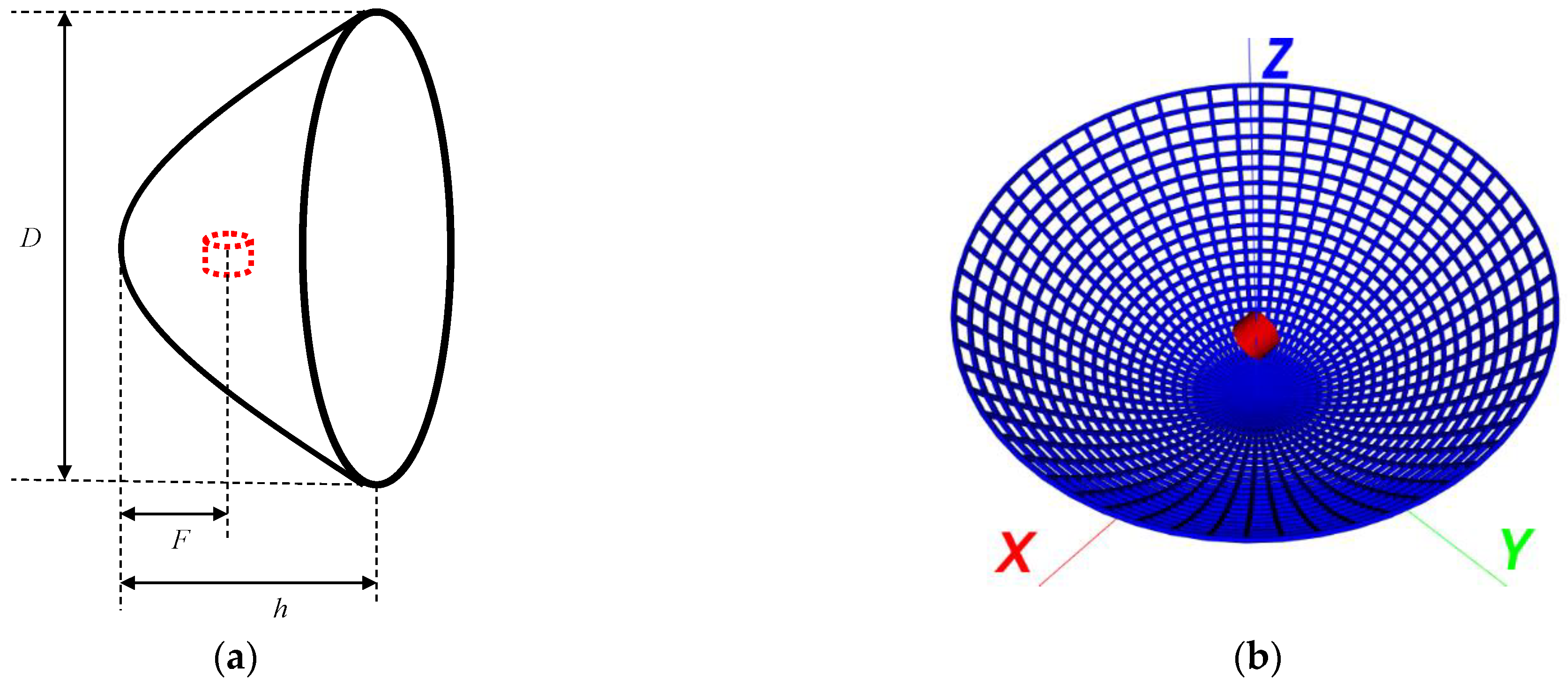
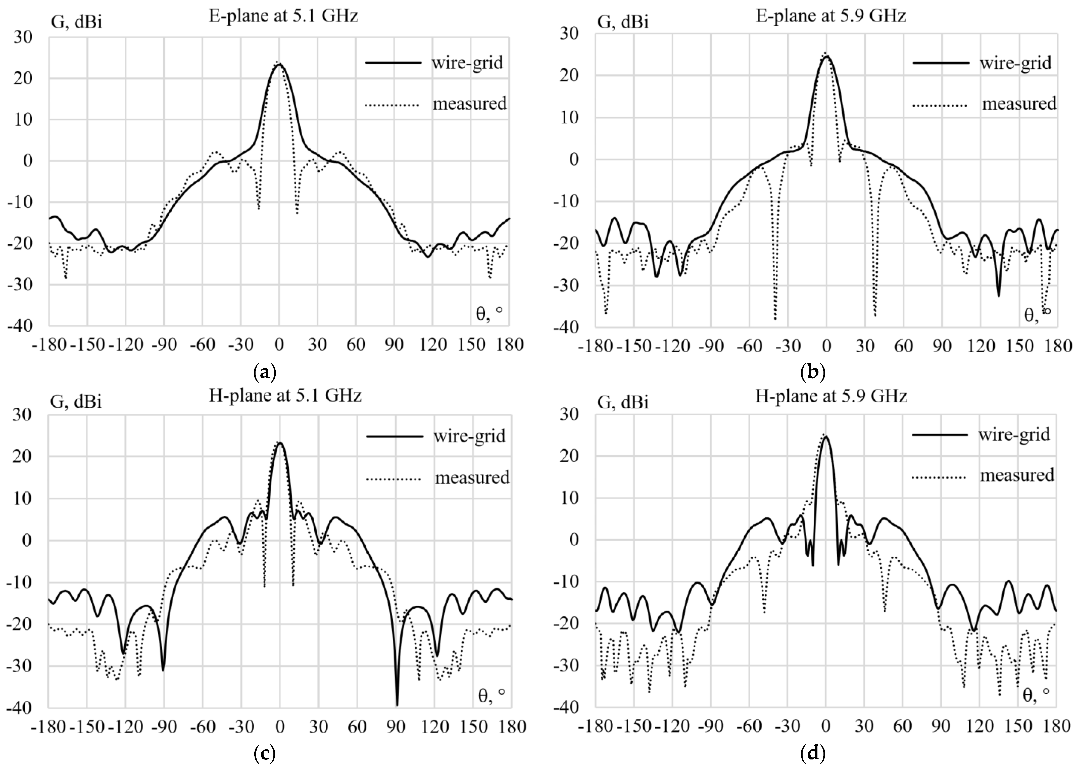
5.3.1. Real Commercial Parabolic Antenna

In order to demonstrate the applicability of OCGA, a dual-polarized parabolic commercial antenna [301] (Figure 5) is used. This antenna is designed for directional links with MIMO mode at the frequency band of 5 GHz. The electrical and mechanical parameters of this antenna are presented in Table 1 and Table 2, respectively [301]. The measured results of the antenna gain are presented in Figure 6 [301].

5.3.2. Modeling Using Wire Grids

The structure of the parabolic antenna is modeled using a MoM wire grid with the thin-wire approximation [302]. The isometric view of the parabolic antenna structure is presented in Figure 7, and its geometrical parameters are as follows: the diameter D = 400 mm, the depth h = 143.6 mm, the focus F = 75 mm. As an excitation source, a dipole is located at a distance equal to the focus of the reflector from the center of the grid, and its length is chosen equal to l = λ/3.6. The dipole radius is chosen equal to R1 = λ/3.6 and the radius of grid wires R2 = λ/30. The wire grid is built using 60 radial wires and 25 horizontal ones (Figure 7). According to the antenna datasheet [301], the simulation using the wire grid is performed at frequencies of 5.1 GHz and 5.9 GHz. The antenna gain is calculated in the E-plane and H-plane, and the results are compared to the measured ones and presented in Figure 8.

5.4. OCGA Method

5.4.1. General OCGA

Using the general OCGA method described above, the sparse antenna was obtained for the modeled antenna from [301]. Two different sparse antennas were obtained only to demonstrate the difference between the resulting sparse structure at each frequency. The current matrix elements were normalized with respect to the maximum current magnitude in structure wires. These sparse structures were obtained taking into account the GEET value equal to 10%. All the elements in which the current value was smaller than 10% of the maximum one were deleted. The resulting structures are presented in Figure 9. The antenna gain calculated using the wire grid (full structure) and those obtained using the general OCGA (sparse structure) are compared and presented in Figure 9 at 5.1 GHz and 5.9 GHz. The results obtained using the sparse antenna comparing to the measured ones and those obtained using the wire grid are consistent. The differences between them can be controlled by the GEET value. Moreover, the difference might arise with the frequency increase as shown in Figure 9. By comparing the full wire-grid structure and the sparse one, we found that the antenna mass reduced by 1.51 times at 5.1 GHz and by 1.42 times at 5.9 GHz. Meanwhile, the computational time spent on antenna modeling also reduced by 3.44 times at 5.1 GHz and by 2.88 times at 5.9 GHz. The required memory also reduced by 2.28 times at 5.1 GHz and by 2.02 times at 5.9 GHz.

5.4.2. Connected OCGA Approach

The structure of the sparse antenna obtained using OCGA might add technical difficulty in manufacturing such antennas, which might differ according to the structure. For example, in the case of sparse printed antennas using OCGA, the antenna’s physical geometry can be manufactured easily, but for reflector antennas, as shown in Figure 9, using OCGA complicates their manufacturing. Since OCGA can be easily optimized and adapted, any condition might be applied depending on the requirements. To demonstrate this capabilities of OCGA, we proposed another approach of obtaining sparse antennas using OCGA. We assumed that the above sparse antenna needs to be manufactured and in order to construct the structure prototype, for example using a 3D printer before metallization, we modified the algorithm of OCGA to give a structure of physically connected wires. In other words, the wires are used only where the current flows. The sparse antennas obtained using this approach and their gain results are compared with those obtained using the wire grid and presented in Figure 10. The results show good consistency, and the structures seem to be easier to manufacture.

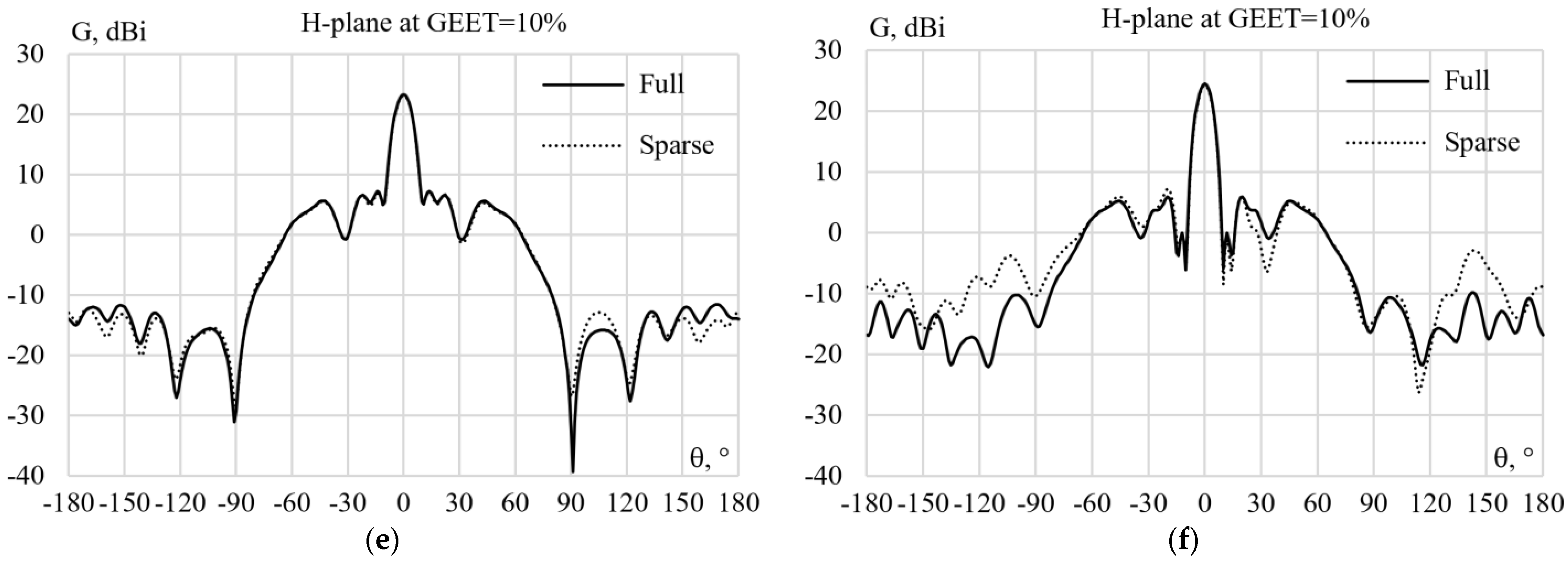
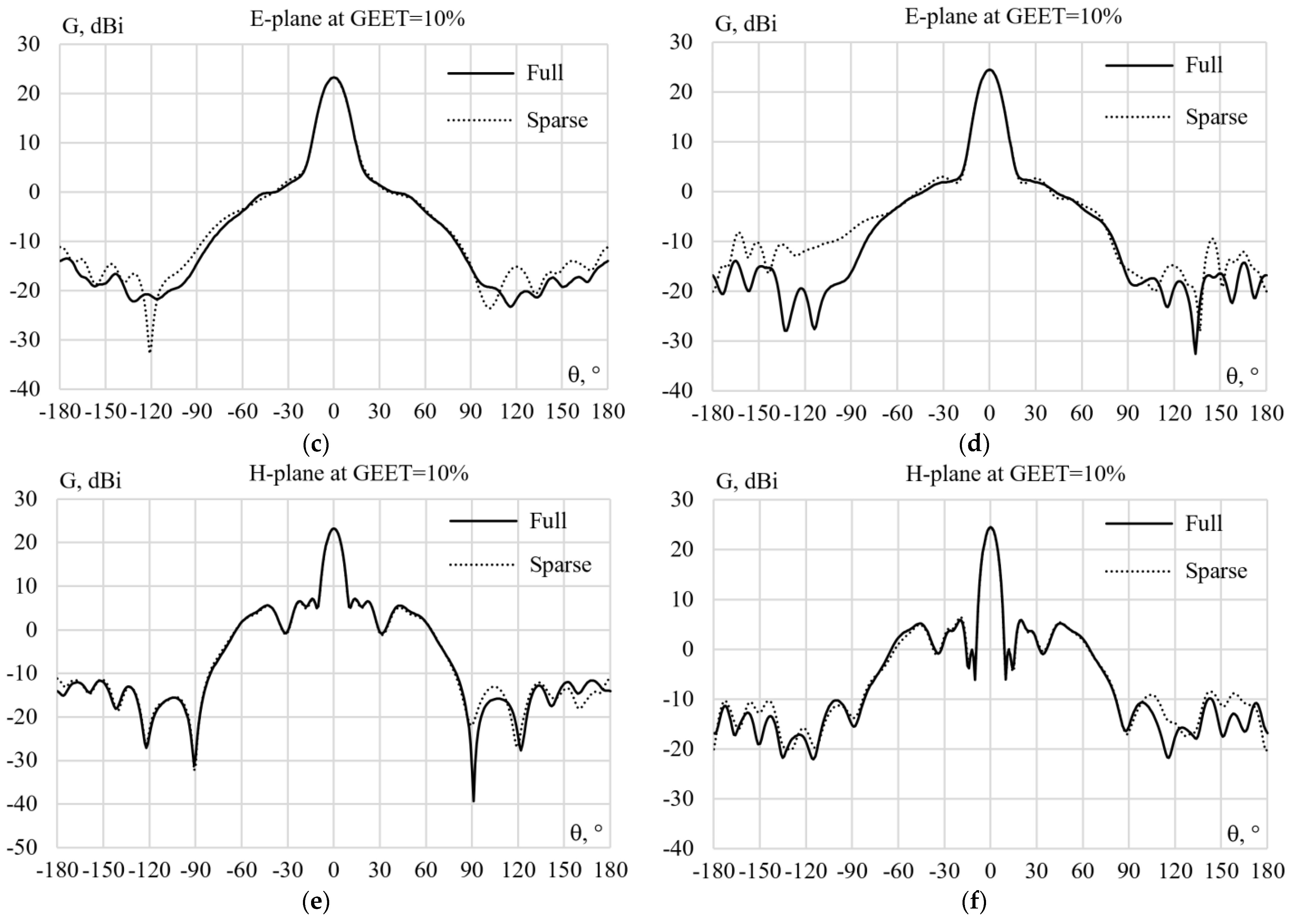
5.4.3. OCGA Sparse Antenna

In order to demonstrate the possibility of using sparse antennas obtained by the OCGA method, we took the sparse antenna obtained at a frequency of 5.9 GHz and modeled it at a frequency of 5.1 GHz. Then, we compared the results and presented them in Figure 11. As can be seen, using the OCGA method to obtain a sparse antenna from an antenna that operates in a frequency range does not significantly affect the characteristics of the new sparse antenna, considering the fact that the surface current flows in a different direction at each frequency.

5.4.4. Discussion and Future Work

The OCGA method is under research and further development. This can be explained from the fact that the rectangular grid is universal for any excitations and frequencies, but is far from optimal (for example, by the criterion of reducing the mass and by the criterion of reducing the computational cost of modeling). Taking into account the arbitrariness of the coordinates of the beginning and end of any wire segment, the optimal grid should repeat the directions of the current on the surface and thickening at the places where the changes in the current are sharp. When modeling, this will reduce the order of the matrix of the SLAE that describes the structure (when modeling using MoM). But modeling the surface with a wire grid, according to the flow of currents over the surface, enables manufacturing the object itself not in the form of a real flat surface but in the form of a wire grid. Indeed, there is no need to use, for example, a sheet of solid metal if currents do not flow through it everywhere; it is necessary to leave the metal only where significant currents flow and remove it where insignificant currents flow. Then, for example, it is advisable to switch: from a wire grid to radial conductors; from a grid of strips with the same width to strips with varying widths in accordance with the current density; or from a solid volume to a certain structure with the combined use of the two previous options. Thus, this idea requires more investigation and further development.
Till now, this method has been applied to simple wire structures (the entries of the SLAE matrix can be calculated even analytically) using the thin-wire approximation (impulse basis functions and Dirac test functions, according to the classical work by Harrington). It is supposed to be used later, even though it requires a correct choice of the segment length at a given wire radius relative to the wavelength.
Further study should consider the possibility of reducing the number of antenna elements with a controllable change of their critical characteristics with a given GEET. This is appropriate to reduce the antenna’s mass, size, sailing, required memory, and computer time consumption in a multivariate analysis or optimization of the structure on a large number of parameters.
In addition, it is crucial to investigate another important aspect: the applicability of the proposed approach. Thus, due to the non-use of unnecessary elements, it seems that this is effective for simple requirements (for example, radiation of the antenna at only one frequency). However, in the case of complex requirements (for example, radiation at several frequencies), the efficiency of this method will reduce. Meanwhile, this conclusion is ambiguous: despite the fact that the antenna currents flow differently at different frequencies, a preliminary study of this method showed the ability of the antenna to work in a fairly wide frequency range, such as 6–9 GHz. Moreover, the amplitudes and directions of the antenna currents changed insignificantly. As a result, the received “sparse” antenna (at a certain GEET) could easily replace the initial one (full grid). Therefore, it is expedient to investigate this question.
Moreover, the possibility and the efficiency of the transition from the orthogonal to the radial wire grid should also be considered, as it will allow the reduction of the redundancy of the orthogonal grid, by reducing by two times the number of segments (by replacing two cathetuses by hypotenuse), and possibly even more, by reducing the number of segments in the polyline (up to the radial line from the source to the structure edge). An illustrative example is the approximation of a biconical antenna by radial conductors only, without transverse ones, because no currents flow in them due to the symmetry.
On other hand, the OCGA itself can be modified as an optimization method to obtain the desired characteristics of the required antenna. Finally, it is possible to hybridize the OCGA with GA to optimize the structure designs, but this will be at the expense of computational costs. In addition, the analysis of the characteristic mode [303] of the antennas obtained using OCGA might help to understand the antenna’s working principle, and to select its excitation location in order to obtain an optimal antenna structure, which should be considered in future studies of the OCGA method.

6. Conclusions

In this paper, we have undertaken an intensive review. At first, we concentrated on MoM and reviewed the studies of other researchers related to MoM and even to other computational methods. We tried to reflect the reasons why MoM investigations are still relevant. We also provided a considerable amount of research related to the use of MoM, as well as various methods used to accelerate the modeling and calculating processes. In addition, we mentioned some of the methods that are used when MoM is combined with other methods. Furthermore, some research in the review contained remarkable examples of using MoM for modeling antennas. Various optimization techniques have also been considered in this review as they are among the most important aspects in modeling antennas. Among these techniques, we considered genetic algorithms (GA) and the studies that employ the combination of MoM and GA in modeling antennas. In addition, we provided a review of reconfigurable and smart antennas followed by wire-grid sparse antennas. We also presented a new method that can be used in both development and modeling of antennas and scatterers, and demonstrated its capabilities.

Author Contributions

Conceptualization, A.A.H. and S.P.K.; methodology, T.R.G. and S.P.K.; software, T.M.N. and A.A.H.; validation, T.M.N. and A.A.H.; formal analysis, S.P.K. and T.R.G.; investigation, A.A.H. and T.R.G.; resources, T.R.G.; data curation, T.M.N.; writing—original draft preparation, S.P.K.; writing—review and editing, A.A.H. and T.R.G.; visualization, T.M.N.; supervision, T.R.G.; project administration, A.A.H. All authors have read and agreed to the published version of the manuscript.

Funding

This research was funded by the Ministry of Science and Higher Education of the Russian Federation project FEWM-2023-0014 and FEWM-2022-0001.

Data Availability Statement

The data presented in this study are available on request from the corresponding author. The data are not publicly available due to the funding organization policy.

Conflicts of Interest

The authors declare no conflict of interest.

References

  1. Kumar, O.P.; Kumar, P.; Ali, T.; Kumar, P.; Vincent, S. Ultrawideband Antennas: Growth and Evolution. Micromachines 2022, 13, 60. [Google Scholar] [CrossRef] [PubMed]
  2. Ojaroudi Parchin, N.; Jahanbakhsh Basherlou, H.; Al-Yasir, Y.I.A.; Abd-Alhameed, R.A.; Abdulkhaleq, A.M.; Noras, J.M. Recent Developments of Reconfigurable Antennas for Current and Future Wireless Communication Systems. Electronics 2019, 8, 128. [Google Scholar] [CrossRef] [Green Version]
  3. Jabbar, A.; Abbasi, Q.H.; Anjum, N.; Kalsoom, T.; Ramzan, N.; Ahmed, S.; Rafi-ul-Shan, P.M.; Falade, O.P.; Imran, M.A.; Ur Rehman, M. Millimeter-Wave Smart Antenna Solutions for URLLC in Industry 4.0 and Beyond. Sensors 2022, 22, 2688. [Google Scholar] [CrossRef] [PubMed]
  4. Ikram, M.; Sultan, K.; Lateef, M.F.; Alqadami, A.S.M. A Road towards 6G Communication—A Review of 5G Antennas, Arrays, and Wearable Devices. Electronics 2022, 11, 169. [Google Scholar] [CrossRef]
  5. Ali, Q.; Shahzad, W.; Ahmad, I.; Safiq, S.; Bin, X.; Abbas, S.M.; Sun, H. Recent Developments and Challenges on Beam Steering Characteristics of Reconfigurable Transmitarray Antennas. Electronics 2022, 11, 587. [Google Scholar] [CrossRef]
  6. Abu Bakar, H.; Abd Rahim, R.; Soh, P.J.; Akkaraekthalin, P. Liquid-Based Reconfigurable Antenna Technology: Recent Developments, Challenges and Future. Sensors 2021, 21, 827. [Google Scholar] [CrossRef] [PubMed]
  7. Tu, Y.; Al-Yasir, Y.I.A.; Ojaroudi Parchin, N.; Abdulkhaleq, A.M.; Abd-Alhameed, R.A. A Survey on Reconfigurable Microstrip Filter–Antenna Integration: Recent Developments and Challenges. Electronics 2020, 9, 1249. [Google Scholar] [CrossRef]
  8. Ojaroudi Parchin, N.; Jahanbakhsh Basherlou, H.; Al-Yasir, Y.I.A.; Abdulkhaleq, A.M.; Abd-Alhameed, R.A. Reconfigurable Antennas: Switching Techniques—A Survey. Electronics 2020, 9, 336. [Google Scholar] [CrossRef] [Green Version]
  9. Zhang, K.; Soh, P.J.; Yan, S. Meta-Wearable Antennas—A Review of Metamaterial Based Antennas in Wireless Body Area Networks. Materials 2021, 14, 149. [Google Scholar] [CrossRef]
  10. Goudarzi, A.; Honari, M.M.; Mirzavand, R. Resonant Cavity Antennas for 5G Communication Systems: A Review. Electronics 2020, 9, 1080. [Google Scholar] [CrossRef]
  11. Chishti, A.R.; Aziz, A.; Qureshi, M.A.; Abbasi, M.N.; Algarni, A.M.; Zerguine, A.; Hussain, N.; Hussain, R. Optically Transparent Antennas: A Review of the State-of-the-Art, Innovative Solutions and Future Trends. Appl. Sci. 2023, 13, 210. [Google Scholar] [CrossRef]
  12. Sharma, P.; Tiwari, R.N.; Singh, P.; Kumar, P.; Kanaujia, B.K. MIMO Antennas: Design Approaches, Techniques and Applications. Sensors 2022, 22, 7813. [Google Scholar] [CrossRef] [PubMed]
  13. Ahmad, I.; Tan, W.; Ali, Q.; Sun, H. Latest Performance Improvement Strategies and Techniques Used in 5G Antenna Designing Technology, a Comprehensive Study. Micromachines 2022, 13, 717. [Google Scholar] [CrossRef]
  14. Benavente-Peces, C.; Herrero-Sebastián, I. Worldwide Coverage Mobile Systems for Supra-Smart Cities Communications: Featured Antennas and Design. Smart Cities 2020, 3, 556–584. [Google Scholar] [CrossRef]
  15. Mirmozafari, M.; Zhang, Z.; Gao, M.; Zhao, J.; Honari, M.M.; Booske, J.H.; Behdad, N. Mechanically Reconfigurable, Beam-Scanning Reflectarray and Transmitarray Antennas: A Review. Appl. Sci. 2021, 11, 6890. [Google Scholar] [CrossRef]
  16. Mohamadzade, B.; Simorangkir, R.B.V.B.; Maric, S.; Lalbakhsh, A.; Esselle, K.P.; Hashmi, R.M. Recent Developments and State of the Art in Flexible and Conformal Reconfigurable Antennas. Electronics 2020, 9, 1375. [Google Scholar] [CrossRef]
  17. Paknys, R.J. The near field of a wire grid model. IEEE Trans. Antennas Propag. 1991, 39, 994–999. [Google Scholar] [CrossRef]
  18. Yatsenko, V.V.; Tretyakov, S.A.; Maslovski, S.I.; Sochava, A.A. Higher order impedance boundary conditions for sparse wire grids. IEEE Trans. Antennas Propag. 2000, 48, 720–727. [Google Scholar] [CrossRef]
  19. Rubinstein, A.; Rachidi, F.; Rubinstein, M. On wire-grid representation of solid metallic surfaces. IEEE Trans. Electromagn. Compat. 2005, 47, 192–195. [Google Scholar] [CrossRef]
  20. Manabe, T.; Murk, A. Transmission and reflection characteristics of slightly irregular wire-grids with finite conductivity for arbitrary angles of incidence and grid rotation. IEEE Trans. Antennas Propag. 2005, 53, 250–259. [Google Scholar] [CrossRef]
  21. Abd-Alhameed, R.A.; Zhou, D.; See, C.H.; Excell, P.S. A Wire-Grid Adaptive-Meshing Program for Microstrip-Patch Antenna Designs Using a Genetic Algorithm [EM Programmer’s Notebook]. IEEE Antennas Propag. Mag. 2009, 51, 147–151. [Google Scholar] [CrossRef]
  22. Zhao, Z.; Zhang, M.; Cui, X.; Li, L. Effect of Wire Grid Covering Aperture on the Shielding Performance of Metal Rectangular Enclosure. IEEE Trans. Magn. 2009, 45, 1068–1071. [Google Scholar] [CrossRef]
  23. Topa, T.; Karwowski, A.; Noga, A. Using GPU With CUDA to Accelerate MoM-Based Electromagnetic Simulation of Wire-Grid Models. IEEE Antennas Wirel. Propag. Lett. 2011, 10, 342–345. [Google Scholar] [CrossRef]
  24. Sallam, M.O.; Vandenbosch, G.A.E.; Gielen, G.G.E.; Soliman, E.A. Novel Wire-Grid Nano-Antenna Array With Circularly Polarized Radiation for Wireless Optical Communication Systems. J. Light. Technol. 2017, 35, 4700–4706. [Google Scholar] [CrossRef]
  25. Happ, F.; Brüns, H.D.; Gronwald, F. An Efficient Implementation of the Periodic Method of Moments for Shielding Effectiveness Calculations of Thin-Wire Grids. In Proceedings of the 2018 2nd URSI Atlantic Radio Science Meeting (AT-RASC), Gran Canaria, Spain, 28 May–1 June 2018; pp. 1–4. [Google Scholar]
  26. Rao, S. A Simple and Efficient Method of Moments Solution Procedure for Solving Time-Domain Integral Equation—Application to Wire-Grid Model of Perfect Conducting Objects. IEEE J. Multiscale Multiphysics Comput. Tech. 2019, 4, 57–63. [Google Scholar] [CrossRef]
  27. Colgan, M.A.; Mirotznik, M.S. Design and Fabrication of 3D Wire Grid Antenna An Integrated Method for Optimization in Constrained Volumes. In Proceedings of the 2020 IEEE International Symposium on Antennas and Propagation and North American Radio Science Meeting, Montreal, QC, Canada, 5–10 July 2020; pp. 1553–1554. [Google Scholar]
  28. Topa, T. Porting Wire-Grid MoM Framework to Reconfigurable Computing Technology. IEEE Antennas Wirel. Propag. Lett. 2020, 19, 1630–1633. [Google Scholar] [CrossRef]
  29. Zhu, X.; Wu, W.; Zhang, G.; Cai, L. Analysis of Radiation Field of a New Wire-grid TEM Horn. In Proceedings of the 2019 Photonics & Electromagnetics Research Symposium—Fall (PIERS—Fall), Xiamen, China, 17–20 December 2019; pp. 3188–3191. [Google Scholar]
  30. Guan, N.; Tayama, H.; Kaushal, S.; Yamaguchi, Y. A wire-grid type transparent film UWB antenna. In Proceedings of the 2017 IEEE-APS Topical Conference on Antennas and Propagation in Wireless Communications (APWC), Verona, Italy, 11–15 September 2017; pp. 166–169. [Google Scholar]
  31. Sallam, M.O.; Serry, M.; Shamim, A.; Sedky, S.; Soliman, E.A. Novel micromachined on-chip 10-elements wire-grid array operating at 60 GHz. In Proceedings of the 2017 11th European Conference on Antennas and Propagation (EUCAP), Paris, France, 19–24 March 2017; pp. 202–206. [Google Scholar]
  32. Hestenes, M.R.; Stiefel, E. Methods of conjugate gradients for solving linear systems. J. Res. Natl. Bur. Stand. 1952, 49, 409–436. [Google Scholar] [CrossRef]
  33. Axelsson, O.; Barker, V.A. Finite Element Solution of Boundary Value Problems: Theory and Computation; Academic: New York, NY, USA, 1984; ISBN 978-089-871-499-9. [Google Scholar]
  34. Yee, K.S. Numerical solution of initial boundary value problems involving Maxwell’s equations in isotropic media. IEEE Trans. Antennas Propag. 1966, 14, 302–307. [Google Scholar]
  35. Taflove, A. Application of the finite-difference time-domain method to sinusoidal steady state electromagnetic penetration problems. IEEE Trans. Electromagn. Compat. 1980, EMC-22, 191–202. [Google Scholar] [CrossRef]
  36. Kunz, K.S.; Luebbers, R.J. The Finite Difference Time Domain Method for Electromagnetics; CRC Press: Boca Raton, FL, USA, 1993; p. 464. ISBN 978-036-740-237-2. [Google Scholar]
  37. Zivanovic, S.S.; Yee, K.S.; Mei, K.K. A subgridding method for the time-domain finite-difference method to solve Maxwell’s equations. IEEE Trans. Microw. Theory Tech. 1991, 39, 471–479. [Google Scholar] [CrossRef]
  38. Chew, W.C. Waves and Fields in Inhomogeneous Media; Van Nostrand Reinhold: New York, NY, USA, 1990; ISBN 978-047-054-705-2. [Google Scholar]
  39. Courant, R. Variational methods for the solution of problems of equilibrium and vibrations. Bull. Am. Math. Soc. 1943, 49, 1–23. [Google Scholar] [CrossRef]
  40. Silvester, P.P.; Ferrari, R.L. Finite Elements for Electrical Engineers, 2nd ed.; Cambridge University Press: Cambridge, UK, 1996; p. 514. ISBN 978-113-917-061-1. [Google Scholar]
  41. Jin, J.M.; Volakis, J.L.; Collins, J.D. A finite element-boundary integral method for scattering and radiation by two- and three-dimensional structures. IEEE Antennas Propag. Mag. 1991, 33, 22–32. [Google Scholar] [CrossRef] [Green Version]
  42. Jin, J.M.; Volakis, J.L. Scattering and radiation analysis of three-dimensional cavity arrays via a hybrid finite-element method. IEEE Trans. Antennas Propag. 1993, 41, 1580–1586. [Google Scholar]
  43. Jin, J.; Lee, S.W. Hybrid finite-element analysis of scattering and radiation by a class of waveguide-fed structures. Microw. Opt. Technol. Lett. 1994, 7, 798–803. [Google Scholar] [CrossRef]
  44. Jin, J.M.; Lu, N. Application of adaptive absorbing boundary condition to finite element solution of three-dimensional scattering. IEEE Proc. Microw. Antennas Propag. 1996, 143, 57–61. [Google Scholar] [CrossRef]
  45. Ling, F.X.; Sheng, Q.; Jin, J.M. Hybrid MoM/SBR and FEM/SBR methods for scattering by large bodies with inhomogeneous protrusions. In Proceedings of the IEEE Antennas and Propagation Society International Symposium, Digest, Montreal, QC, Canada, 13–18 July 1997; Volume 2, pp. 644–647. [Google Scholar]
  46. Sheng, X.Q.; Jin, J.M.; Song, J.; Lu, C.C.; Chew, W.C. On the formulation of hybrid finite-element and boundary-integral methods for 3-D scattering IEEE Trans. Antennas Propag. 1998, 46, 303–311. [Google Scholar] [CrossRef]
  47. Forgy, E.A.; Chew, W.C.; Jin, J.M. A hybrid MoM/FDTD technique for studying human head/antenna interactions. In Proceedings of the IEEE-APS Conference on Antennas and Propagation for Wireless Communications (Cat. No. 98EX184), Waltham, MA, USA, 1–4 November 1998; pp. 81–84. [Google Scholar]
  48. Desai, C.S.; Abel., J.F. Introduction to the Finite Element Method: A Numerical Approach for Engineering Analysis; Van Nostrand Reinhold: New York, NY, USA, 1972; p. 477. ISBN 978-044-222-083-9. [Google Scholar]
  49. Silvester, P.; Chari, M. Finite element solution of saturate magnetic field problems. IEEE Trans. Power Appar. Syst. 1970, 89, 1642–1651. [Google Scholar] [CrossRef]
  50. Jin, J.M. The Finite Element Method in Electromagnetics, 3rd ed.; Wiley: Hoboken, NJ, USA, 2014; p. 876. ISBN 978-1-118-84198-3. [Google Scholar]
  51. Monk, P. Finite Element Methods for Maxwell’s Equations; Clarendon Press: Oxford, UK, 2003; p. 450. ISBN 978-019-850-888-5. [Google Scholar]
  52. Jin, J.M.; Liepa, V.V. A note on hybrid finite element method for solving scattering problems. IEEE Trans. Antennas Propag. 1988, 36, 1486–1490. [Google Scholar] [CrossRef]
  53. Nasir, M.A.; Chew, W.C.; Raghaven, P.; Heath, M.T. O(N15) solution of hybrid FEM problems. In Proceedings of the IEEE Antennas and Propagation Society International Symposium and URSI National Radio Science Meeting, Seattle, WA, USA, 20–24 June 1994; pp. 447–450. [Google Scholar]
  54. George, A. Nested dissection of a regular finite element mesh. SIAM J. Numer. Anal. 1973, 10, 345–363. [Google Scholar] [CrossRef]
  55. Bayliss, A.; Goldstein, C.I.; Turkel, E. On accuracy conditions for the numerical computation of waves. J. Comput. Phys. 1985, 59, 396–404. [Google Scholar] [CrossRef]
  56. Scott, W.R. Errors due to spatial discretization and numerical precision in the finite-element method. IEEE Trans. Antennas Propag. 1994, 42, 1565–1570. [Google Scholar] [CrossRef]
  57. Lee, R.; Cangellaris, A.C. A study of discretization error in the finite element approximation of wave solution. IEEE Trans. Antennas Propag. 1992, 40, 542–549. [Google Scholar] [CrossRef]
  58. Deveze, T.; Beaulieu, L.; Tabbara, W. A fourth-order scheme for the FDTD algorithm applied to Maxwell’s equations. In Proceedings of the IEEE Antennas and Propagation Society International Symposium 1992 Digest, Chicago, IL, USA, 20–24 July 1992; pp. 346–349. [Google Scholar]
  59. Manry, C.W.; Broschat, S.L.; Schneider, J.B. Higher-order FDTD methods for large problems. Appl. Comput. Electromagn. Soc. J. (ACES) 1995, 10, 17–29. [Google Scholar]
  60. Harrington, R.F. Matrix methods for field problems. Proc. IEEE 1967, 55, 136–149. [Google Scholar] [CrossRef] [Green Version]
  61. Jobava, R.; Bogdanov, F.; Gheonjian, A.; Frei, S. Application of adaptive scheme for the Method of Moments in EMC automotive problems. In Proceedings of the 16th International Zurich EMC Symposium, Zurich, Switzerland, 13–18 February 2005; pp. 131–136. [Google Scholar]
  62. Davidson, D.B. Computational Electromagnetics for RF and Microwave Engineering, 2nd ed.; University Press: Cambridge, UK, 2011; p. 505. ISBN 978-051-177-811-7. [Google Scholar]
  63. Bonsall, F.F.; Kantorovich, L.V.; Akilov, G.P. Functional Analysis in Normed Spaces; Translated from the Russian by D. E. Brown; Robertson, A.P., Ed.; Pergamon Press: Oxford, UK, 1964; p. 771. [Google Scholar]
  64. Kravchuk, M.F. Application of the Method of Moments to the Solution of Linear Differential and Integral Equations; Science Academy Journal: Kiev, Ukrain, 1932; Volume 1. [Google Scholar]
  65. Fletcher, K. Numerical Methods Based on the Galerkin Method; Mir: Moscow, Russia, 1988; p. 352. [Google Scholar]
  66. Harrington, R.F. Field Computation by Moment Methods; Macmillan: New York, NY, USA, 1968; p. 240. [Google Scholar]
  67. Swanson, D.G.; Hofer, W.J. Microwave Circuit Modeling Using Electromagnetic Field Simulation; Artech House Publishers: Norwood, SA, Australia, 2003; p. 474. ISBN 978-158-053-308-9. [Google Scholar]
  68. Crandall, S.H. Engineering Analysis; McGraw-Hill: New York, NY, USA, 1956; p. 417. [Google Scholar]
  69. Ames, W.F. Nonlinear Partial Differential Equations in Engineering; Academic Press: New York, NY, USA, 1965; p. 305. ISBN 978-148-322-292-9. [Google Scholar]
  70. Finlayson, B.A. The Method of Weighted Residuals and Variational Principles; Academic Press: New York, NY, USA, 1972; p. 412. ISBN 978-161-197-323-5. [Google Scholar]
  71. Finlayson, A.; Scriven, L.E. The method of weighted residuals: A review. Appl. Mech. Rev. 1966, 19, 735–748. [Google Scholar]
  72. Afendikova, N.G. History of Galerkin’s Method and Its Role in M.B. Keldysh’s Work; Institute of Applied Mathematics Named after M.B. Keldysh, Russian Academy of Sciences: Moscow, Russia, 2014; p. 16, Preprint No. 77. (In Russian) [Google Scholar]
  73. Young, L. Orthogonal collocation revisited. Comput. Methods Appl. Mech. Eng. 2019, 345, 1033–1076. [Google Scholar] [CrossRef]
  74. Lucka, T.F.; Lucka, A.Y. Development of direct methods in mathematical physics in the works of M. P. Kravchuk. Ukr. Math. J. 1992, 44, 931–939. [Google Scholar]
  75. Kutateladze, S.S.; Makarov, V.L.; Romanovsky, J.V. The scientific legacy of LV Kantorovich (1912–1986). Sib. Zhurnal Ind. Mat. 2001, 4, 3–17. [Google Scholar]
  76. Jansen, R.H. The spectral-domain approach for microwave integrated circuits. IEEE Trans. Microw. Theory Tech. 1985, 33, 1043–1056. [Google Scholar] [CrossRef]
  77. Mosig, J.R. Integral equation technique. In Numerical Techniques for Microwave and Millimeter-Wave Passive Structures; Itoh, T., Ed.; Wiley: New York, NY, USA, 1989; pp. 133–213. [Google Scholar]
  78. Rautio, J.C.; Harrington, R.F. An electromagnetic time-harmonic analysis of shielded microstrip circuits. IEEE Trans. Microw. Theory Tech. 1987, 35, 726–730. [Google Scholar] [CrossRef] [Green Version]
  79. Dunleavy, L.P.; Katehi, P.B. A generalized method for analyzing shielded thin microstrip discontinuities. IEEE Trans. Microw. Theory Tech. 1988, 36, 1758–1766. [Google Scholar] [CrossRef]
  80. Horng, T.-S.; McKinzie, W.E.; Alexopoulos, N.G. Full-wave spectral-domain analysis of compensation of microstrip discontinuities using triangular subdomain functions. IEEE Trans. Microw. Theory Tech. 1992, 40, 2137–2147. [Google Scholar] [CrossRef] [Green Version]
  81. Becks, T.; Wolff, I. Analysis of 3-D metallization structures by a full-wave spectral domain technique. IEEE Trans. Microw. Theory Tech. 1992, 40, 2219–2227. [Google Scholar] [CrossRef]
  82. Nmhadham, K.; Nuteson, T.W. Efficient analysis of passive microstnp elements in MMICs. Int. J. Microw. Millim.-Wave Comput.-Aided Eng. 1994, 4, 219–229. [Google Scholar]
  83. Chew, W.C.; Jin, J.M.; Lu, C.C.; Michielssen, E.; Song, J.M. Fast solution methods in electromagnetics. IEEE Trans. Antennas Propag. 1997, 45, 533–543. [Google Scholar] [CrossRef] [Green Version]
  84. Sarkar, T.K. On the application of the generalized biconjugate gradient method. J. Electromagn. Waves Appl. 1987, 1, 223–242. [Google Scholar] [CrossRef]
  85. Naishadam, K.; Misra, P. Order recursive method of moments: A powerful computational tool for microwave CAD and optimization. In Proceedings of the IEEE MTT-S International Microwave Symposium Digest, San Francisco, CA, USA, 22–27 May 1996; pp. 1463–1466. [Google Scholar]
  86. Rokhlin, V. Rapid solution of integral equations of scattering theory in two dimensions. J. Comput. Phys. 1990, 36, 414–439. [Google Scholar] [CrossRef]
  87. Canning, F.X. Transformations that produce a sparse moment matrix. J. Electromagn. Waves Appl. 1990, 4, 893–913. [Google Scholar] [CrossRef]
  88. Boag, A.; Mittra, R. Complex multipole beam approach to electromagnetic scattering problems. IEEE Trans. Antennas Propag. 1994, 42, 366–372. [Google Scholar] [CrossRef]
  89. Chang, D.C.; Zheng, J.-X. Electromagnetic modeling of passive circuit elements in MMIC. IEEE Trans. Microw. Theory Tech. 1992, 40, 1741–1747. [Google Scholar] [CrossRef]
  90. Misra, P. Order recursive Gaussian elimnation. IEEE Trans. Aerosp. Electron. Syst. 1996, 32, 396–400. [Google Scholar] [CrossRef]
  91. Johnson, J.M.; Rahmat-Samii, Y. Genetic algorithms and method of moments (GA/MOM) for the design of integrated an-tennas. IEEE Trans. Antennas Propag. 1999, 47, 1606–1614. [Google Scholar] [CrossRef]
  92. Loison, R.; Gillard, R.; Citerne, J.; Piton, G.; Legay, H. Optimized 2D multi-resolution method of moments for printed antenna array modeling. IEE Proc. Microw. Antennas Propag. 2001, 148, 1–8. [Google Scholar] [CrossRef]
  93. Cormos, D.; Loison, R.; Gillard, R.A. multistructure method of moments for EM optimization. Microw. Opt. Technol Lett. 2004, 40, 114–117. [Google Scholar] [CrossRef]
  94. Stavtsev, S.L. Block LU Preconditioner for the Electric Field Integral Equation. In Proceedings of the PIERS 2015 Prague—Progress in Electromagnetics Research Symposium, Proceedings, Prague, Czech Republic, 6–9 July 2015; pp. 1523–1527. [Google Scholar]
  95. Il’in, V.P. Problems of parallel solution of large systems of linear algebrai equations. J. Math. Sci. 2016, 216, 795–804. [Google Scholar] [CrossRef]
  96. Li, R.; Saad, Y. Divide and conquer low-rank preconditioners for symmetric matrices. SIAM J. Sci. Comput. 2013, 35, A2069–A2095. [Google Scholar] [CrossRef]
  97. Carson, E.; Knight, N.; Demmel, J. Avoiding communication in nonsymmetric Lanczosbased Krylov subspace methods. SIAM J. Sci. Comput. 2013, 35, S42–S61. [Google Scholar] [CrossRef]
  98. Bebendorf, M.; Kramer, F. Hierarchical matrix preconditioning for low-frequency-full-Maxwell simulations. Proc. IEEE 2013, 101, 423–433. [Google Scholar] [CrossRef]
  99. Shaeffer, J. Million Plus Unknown MOM LU Factorization on a PC. In Proceedings of the International Conference on Electromagnetics in Advanced Applications (ICEAA), Turin, Italy, 7–11 September 2015; pp. 62–65. [Google Scholar]
  100. Puzyrev, V.; Cela, J.M. A review of block Krylov subspace methods for multisource electromagnetic modeling. Geophys. J. Int. 2015, 202, 1241–1252. [Google Scholar] [CrossRef] [Green Version]
  101. Birk, S. Deflated Shifted Block Krylov Subspace Methods for Hermitian Positive Definite Matrices. Ph.D. Thesis, Fachbereich Mathematik und Naturwissenschaften der Bergischen Universität Wuppertal, Wuppertal, Germany, 2015. [Google Scholar]
  102. Olyslager, F.; De Zutter, D.; Blomme, K. Rigorous analysis of the propagation characteristics of general lossless and lossy multiconductor transmission lines in multilayered media. IEEE Trans. Microw. Theory Tech. 1993, 41, 79–88. [Google Scholar] [CrossRef] [Green Version]
  103. Gillard, R.; Citerne, J. An electromagnetic optimization of microwave and millimeter-wave planar circuits with the use of the method of moments. Microw. Opt. Technol Lett. 1996, 12, 298–301. [Google Scholar] [CrossRef]
  104. Bretones, A.R.; Martin, R.G.; Rubio, R.G.; Garcia, S.G.; Pantoja, M.F. On the simulation of a GPR using an ADI-FDTD/MoMTD hybrid method. In Proceedings of the Tenth International Conference on Grounds Penetrating Radar, GPR 2004, Delft, The Netherlands, 21–24 June 2004; pp. 13–15. [Google Scholar]
  105. Zhou, B.; Lou, J.; Tu, Z.; Xing, F. An FDTD/MoMTD hybrid technique for modeling HF antennas located on lossy ground. In Proceedings of the 2008 International Conference on Microwave and Millimeter Wave Technology, Nanjing, China, 21–24 April 2008; pp. 726–729. [Google Scholar]
  106. Chakarothai, J.; Wang, J.; Fujiwara, O.; Wake, K.; Watanabe, S. A Hybrid MoM/FDTD Method for Dosimetry of Small Animal in Reverberation Chamber. IEEE Trans. Electromagn. Compat. 2014, 56, 549–558. [Google Scholar] [CrossRef]
  107. Chakarothai, J.; Kojima, M.; Sasaki, K.; Suzuki, Y.; Taki, M.; Wake, K.; Watanabe, S. Analysis of millimeter-wave exposure on rabbit eye using a hybrid PMCHWT-MoM-FDTD method. In Proceedings of the International Symposium on Antennas & Propagation, Nanjing, China, 23–25 October 2013; pp. 59–62. [Google Scholar]
  108. Karwowski, A.; Noga, A. Fast MM-PO-based numerical modelling technique for wideband analysis of antennas near conducting objects. Electron. Lett. 2007, 43, 486–487. [Google Scholar] [CrossRef]
  109. Karwowski, A.; Noga, A. Wide-band hybrid MM-PO computational electromagnetics technique using [Z] matrix interpolation and adaptive frequency sampling. In Proceedings of the IEEE International Symposium on Electromagnetic Compatibility, Honolulu, HI, USA, 8–13 July 2007; pp. 1–4. [Google Scholar]
  110. Bingle, M.; Burger, W.; Ludick, D.; Schoeman, M.; van Tonder, J.; Jakobus, U. Method of moments accelerations and extensions in FEKO. In Proceedings of the 2011 International Conference on Electromagnetics in Advanced Applications, Turin, Italy, 12–16 September 2011; pp. 62–65. [Google Scholar]
  111. Commens, M.; Zhao, K. Efficient large scale simulations with a hybrid finite element boundary integral technique. In Proceedings of the WAMICON 2012 IEEE Wireless & Microwave Technology Conference, Cocoa Beach, FL, USA, 15–17 April 2012; pp. 1–4. [Google Scholar]
  112. Mei, K.K. On the integral equations of thin wire antennas. IEEE Trans. Antennas Propag. 1965, 13, 374–378. [Google Scholar] [CrossRef] [Green Version]
  113. Tang, C. Input impedance of arc antennas and short helical radiators. IEEE Trans. Antennas Propag. 1964, 12, 2–9. [Google Scholar] [CrossRef]
  114. Nie, Z.; Que, X. Analysis of wire antennas mounted on large perfectly conducting platforms using MLFMA. J. Syst. Eng. Electron. 2007, 18, 679–684. [Google Scholar]
  115. Cui, T.J.; Chew, W.C. Accurate model of arbitrary wire antennas in free space, above or inside ground. IEEE Trans. Antennas Propag. 2000, 48, 482–493. [Google Scholar]
  116. Altman, Z.; Mittra, R.; Boag, A. New designs of ultra-wide–band communication antennas using a genetic algorithm/Z. Altman. IEEE Trans. Antennas Propag. 1997, 45, 1494–1501. [Google Scholar] [CrossRef]
  117. Altshuler, E.E. Electrically small self-resonant wire antennas optimized using a genetic algorithm. IEEE Trans. Antennas Propag. 2002, 50, 297–300. [Google Scholar] [CrossRef]
  118. Balanis, C.A. Antenna Theory: Analysis and Design, 3rd ed.; John Wiley & Sons: New York, NY, USA, 2005; p. 1097. ISBN 978-111-917-899-6. [Google Scholar]
  119. Schantz, H.G. The Art and Science of Ultrawideband Antennas, 2nd ed.; Artech House: Boston, MA, USA; London, UK, 2015; p. 591. ISBN 978-160-807-955-1. [Google Scholar]
  120. Stutzman, W.L.; Thiele, G.A. Antenna Theory and Design, 3rd ed.; John Wiley & Sons: New York, NY, USA, 2012; p. 598. ISBN 978-047-057-664-9. [Google Scholar]
  121. Tesche, F.M.; Ianoz, M.; Karlsson, T. EMC Analysis Methods and Computational Models; Wiley-Interscience: New York, NY, USA, 1996; p. 656. ISBN 978-0-471-15573-7. [Google Scholar]
  122. Pocklington, H.C. Electrical oscillations in wires. Math. Proc. Camb. Philos. Soc. 1897, 9, 324–332. [Google Scholar]
  123. Hallen, E. Theoretical Investigation into the Transmitting and Receiving Qualities of Antennas; Nova Acta Regiae Societatis Scientiarum Upsaliensis IV: Uppsala, Sweden, 1938; pp. 1–44. [Google Scholar]
  124. Levin, B.M. The Theory of Thin Antennas and Its Use in Antenna Engineering; Bentham Science Publishers: Sharjah, United Arab Emirates, 2013; p. 318. ISBN 978-1-60805-774-0. [Google Scholar]
  125. King, R.W.P.; Smith, G.S.; Owens, M.; Wu, T.T. Antennas in Matter: Fundamentals Theory and Applications; MIT Press: Cambridge MA, USA, 1981. [Google Scholar]
  126. Richmond, J.H. Digital computer solution of the rigorous equations for scattering problems. Proc. IEEE 1965, 53, 796–804. [Google Scholar] [CrossRef] [Green Version]
  127. Werner, D.H.; Werner, P.L.; Breakall, J.K. Some computational aspects of Pocklington electric field integral equation for thin wires. IEEE Trans. Antennas Propag. 1994, 42, 561–563. [Google Scholar] [CrossRef]
  128. Kraus, J.D.; Marhefka, R.J. Antennas for All Applications, 3rd ed.; McGraw-Hill: New Delhi, India, 2006; p. 892. ISBN 978-007-232-103-6. [Google Scholar]
  129. Vorozhtsov, E.V.; Shapeev, V.P. On combining the techniques for convergence acceleration of iteration processes during the numerical solution of Navier-Stokes equations. Num. Meth. Prog. 2017, 18, 80–102. [Google Scholar]
  130. Pissanetzky, S. Sparse Matrix Technology; Academic Press: London, UK, 1984; p. 321. [Google Scholar]
  131. Tewarson, R.P. Sparse Matrices; Academic Press: Cambridge, MA, USA, 1973; p. 160. [Google Scholar]
  132. Saad, Y. Iterative Methods for Sparse Linear Systems, 2nd ed.; SIAM: Philadelphia, PA, USA, 2003; p. 547. ISBN 978-089-871-534-7. [Google Scholar]
  133. Das, A.; Nair, R.R.; Gope, D. Efficient adaptive mesh refinement for MoM-based package-board 3D full-wave extraction. In Proceedings of the IEEE 22nd Conference on Electrical Performance of Electronic Packaging and Systems, San Jose, CA, USA, 27–30 October 2013; pp. 239–242. [Google Scholar]
  134. Sarkar, T.K.; Djordjevic, T.K.; Arvas, E. On the choice of expansion and weighting functions in the numerical solution of operator equations. IEEE Trans. Antennas Propag. 1985, 33, 988–996. [Google Scholar] [CrossRef]
  135. Klein, C.A.; Mittra, R. The effect of different testing functions in the moment method solution of thin–wire antenna problem. IEEE Trans. Antennas Propag. 1975, 23, 258–261. [Google Scholar] [CrossRef]
  136. Sarkar, T.K. Nonconvergence results for the application of the moment method (Galerkin’s method) for some simple problems. In Proceedings of the Antennas and Propagation Society International Symposium, Quebec, QC, Canada, 2–6 June 1980; pp. 676–679. [Google Scholar]
  137. Xunwang, Z.; Zhongchao, L.; Yu, Z. Performance of parallel out-of-core MoM accelerated by SSD. In Proceedings of the IEEE International Symposium on Antennas and Propagation & USNC/URSI National Radio Science Meeting, Vancouver, BC, Canada, 19–24 July 2015; pp. 562–563. [Google Scholar]
  138. Hai, L.; Mei, X.; Zhang, Y. OpenMP-CUDA accelerated moment method for homogeneous dielectric objects. In Proceedings of the 2014 IEEE Antennas and Propagation Society International Symposium (APSURSI), Memphis, TN, USA, 6–11 July 2014; pp. 1634–1635. [Google Scholar]
  139. Kuksenko, S.P.; Gazizov, T.R.; Kostarev, I.S. Approximation of an initial matrix by a Toeplitz one for acceleration of iterative solution of dense linear algebraic systems in scattering problems. In Proceedings of the International Siberian Conference on Control and Communications (SIBCON 2016), Moscow, Russia, 12−14 May 2016; pp. 1–5. [Google Scholar]
  140. Tyrtyshnikov, E.E. Incomplete Cross Approximation in the Mosaic-Skeleton Method. Computing 2000, 64. [Google Scholar] [CrossRef]
  141. Antonini, G.; Orlandi, A.; Ruehli, A.E. Analytical integration of quasi–static potential integrals on nonorthogonal coplanar quadrilaterals for the PEEC method. IEEE Trans. Electromagn. Compat. 2002, 44, 399–403. [Google Scholar] [CrossRef]
  142. John, A.; Jansen, R.H. Evolutionary generation of (M)MIC component shapes using 2.5 D EM simulation and discrete genetic optimization. In Proceedings of the 1996 IEEE MTT-S International Microwave Symposium Digest, San Francisco, CA, USA, 17–21 June 1996; pp. 745–748. [Google Scholar]
  143. Luenberger, D.G. Introduction to Linear and Nonlinear Programming, Reading, 2nd ed.; Addison Wesley: Boston, MA, USA, 1973; p. 554. ISBN 978-020-104-347-1. [Google Scholar]
  144. Arora, J.S. Introduction to Optimum Design, 4th ed.; McGraw-Hill: New York, NY, USA, 2017; p. 968. ISBN 978-012-800-806-5. [Google Scholar]
  145. Goldberg, D.E. Genetic Algorithms in Search, Optimization and Machine Learning, 13th ed.; Addison-Wesley: Boston, MA, USA, 1989; ISBN 978-0201157673. [Google Scholar]
  146. Davis, L. Genetic Algorithms and Simulated Annealing; Pitman: London, UK, 1987. [Google Scholar]
  147. Rudolph, G. Convergence analysis of canonical genetic algorithms. IEEE Trans. Neural Netw. 1994, 5, 96–101. [Google Scholar] [CrossRef] [Green Version]
  148. Davis, L. Handbook of Genetic Algorithms; Thomson Publishing Group: New York, NY, USA, 1991; p. 385. ISBN 978-04-4200-173-5. [Google Scholar]
  149. Goldberg, D.E.; Deb, K.; Clark, J.H. Genetic algorithms, noise, and the sizing of populations. Complex Syst. 1992, 6, 333–362. [Google Scholar]
  150. Holland, J.H. Adaptation in Natural and Artificial Systems; The University of Michigan Press: Ann Arbor, MI, USA, 1975; p. 232. ISBN 978-02-6258-111-0. [Google Scholar]
  151. De Jong, K.A. An Analysis of the Behavior of a Class of Genetic Adaptive Systems. Ph.D. Thesis, University of Michigan, Ann Arbor, MI, USA, 1975. [Google Scholar]
  152. Sridharan, B. Modifications in Genetic Algorithm using additional parameters to make them computationally efficient. In Proceedings of the 2010 IEEE 2nd International Advance Computing Conference (IACC) 2010, Patiala, India, 19–20 February 2010; pp. 55–59. [Google Scholar]
  153. Sywerda, G. Uniform Crossover in Genetic Algorithms. In Proceedings of the Third International Conference on Genetic Algorithms and their Applications, 4–7 June 1989; Schaffer, J.D., Ed.; Morgan Kaufmann: Burlington, MA, USA, 1989; pp. 2–9. [Google Scholar]
  154. Haupt, R.L.; Haupt, S.E. Continuous Parameter vs. Binary Genetic Algorithms. In Proceedings of the Applied Computational Electro-magnetics Society Symposium, Monterey, CA, USA, 17–21 March 1997; Volume II; pp. 1387–1392. [Google Scholar]
  155. Weile, D.S.; Michielssen, E. Community-Based Evolutionary Optimization of Frequency Selective Surfaces. In Proceedings of the 1996 URSI Symposium, Baltimore, MD, USA, 21–26 July 1996; p. 345. [Google Scholar]
  156. Duan, D.W.; Rahmat-Samii, Y. A Generalized Diffraction Synthesis Technique for High Performance Reflector Antennas. IEEE Trans. Antennas Propag. 1995, 43, 27–40. [Google Scholar] [CrossRef]
  157. Ilavarasan, P.; Rothwell, E.J.; Chen, K.; Nyquist, D.P. Natural Resonance Extraction from Multiple Data Sets Using Genetic Algorithm. IEEE Trans. Antennas Propag. 1995, 43, 900–904. [Google Scholar] [CrossRef]
  158. Michielssen, E.; Sajer, J.; Ranjithan, S.; Mittra, R. Design of Lightweight, Broad-Band Microwave Absorbers Using Genetic Algorithms. IEEE Trans. Microw. Theory Tech. 1993, 41, 1024–1031. [Google Scholar] [CrossRef]
  159. Haupt, R.L. An Introduction to Genetic Algorithms for Electromagnetic. IEEE Antennas Propag. Mag. 1995, 37, 7–15. [Google Scholar] [CrossRef] [Green Version]
  160. Uler, G.F.; Mohammed, O.A.; Koh, C.S. Utilizing genetic algorithms for the optimal design of electromagnetic devices. IEEE Trans. Magn. 1994, 30, 4296–4298. [Google Scholar] [CrossRef]
  161. Johnson, J.M.; Rahmat-Samii, Y. Genetic Algorithms in Electromagnetics. In Proceedings of the IEEE Antennas and Propagation Society International Symposium, 1996 Digest, Baltimore, MD, USA, 21–26 July 1996; pp. 1480–1483. [Google Scholar]
  162. Weile, D.S.; Michielssen, E. Genetic algorithm optimization applied to electromagnetics: A review. IEEE Trans. Antennas Propag. 1997, 45, 343–353. [Google Scholar] [CrossRef]
  163. Jones, D.P.; Sabet, K.F.; Cheng, J.; Katehi, L.P.B.; Sarabandi, K.; Harvey, J.F. An accelerated hybrid genetic algorithm for optimization of electromagnetic structures. In Proceedings of the IEEE Antennas and Propagation Society International Symposium, 1999 Digest, Held in Conjunction with: USNC/URSI National Radio Science Meeting (Cat. No. 99CH37010), Orlando, FL, USA, 11–16 July 1999; pp. 426–429. [Google Scholar]
  164. Haupt, R.L. Optimum population size and mutation rate for a simple real genetic algorithm that optimizes array factors. In Proceedings of the IEEE Antennas and Propagation Society International Symposium, Transmitting Waves of Progress to the Next Millennium, 2000 Digest, Held in Conjunction with: USNC/URSI National Radio Science Meeting C, Salt Lake City, UT, USA, 16–21 July 2000; pp. 1034–1037. [Google Scholar]
  165. Johnson, J.M.; Rahmat-Samii, Y. Genetic Algorithms Optimization of Wireless Communication Networks. In Proceedings of the IEEE Antennas and Propagation Society International Symposium, 1995 Digest, Newport Beach, CA, USA, 18–23 June 1995; pp. 1964–1967. [Google Scholar]
  166. Haupt, S.E.; Haupt, R.L. Phase-only adaptive nulling with a genetic algorithm. IEEE Trans. Antennas Propag. 1997, 45, 1009–1015. [Google Scholar] [CrossRef] [Green Version]
  167. Sherman, K.N. Phased array shaped multi-beam optimization for LEO satellite communications using a genetic algorithm. In Proceedings of the 2000 IEEE International Conference on Phased Array Systems and Technology (Cat. No. 00TH8510), Dana Point, CA, USA, 21–25 May 2000; pp. 501–504. [Google Scholar]
  168. Chambers, B.; Tennant, A. Design of wideband Jaumann radar absorbers with optimum oblique incidence performance. Electron. Lett. 1994, 30, 1530–1532. [Google Scholar] [CrossRef]
  169. Mosallaei, H.; Rahmat-Samii, Y. RCS reduction of canonical targets using genetic algorithm synthesized RAM. IEEE Trans. Antennas Propag. 2000, 48, 1594–1606. [Google Scholar] [CrossRef]
  170. Nishino, T.; Itoh, T. Evolutionary generation of microwave line-segment circuits by genetic algorithms. IEEE Trans. Microw. Theory Tech. 2002, 50, 2048–2055. [Google Scholar] [CrossRef]
  171. Hussein, Y.A.; El-Ghazaly, S.M. Modeling and optimization of microwave devices and circuits using genetic algorithms. IEEE Trans. Microw. Theory Tech. 2004, 52, 329–336. [Google Scholar] [CrossRef]
  172. Johnsonm, J.M.; Rahmat-Samii, Y. Genetic algorithm optimization and its application to antenna design. In Proceedings of the IEEE Antennas and Propagation Society International Symposium and URSI National Radio Science Meeting, Seattle, WA, USA, 20–24 June 1994; pp. 326–329. [Google Scholar]
  173. Linden, D.S.; Altshuler, E.E. Automating Wire Antenna Design Using Genetic Algorithms. Microw. J. 1996, 39, 74–86. [Google Scholar]
  174. Boag, A.; Boag, A.; Michielssen, E.; Mittra, R. Design of Electrically Loaded Wire Antennas using Genetic Algorithms. IEEE Trans. Antennas Propag. 1996, 44, 687. [Google Scholar] [CrossRef]
  175. Rogers, S.D.; Butler, C.M.; Martin, A.Q. Realization of a genetic-algorithm-optimized wire antenna with 5:1 bandwidth. Radio Sci. 2001, 36, 1315–1325. [Google Scholar] [CrossRef]
  176. Mosallaei, H.; Rahmat-Samii, Y. Non-uniform Luneburg lens antennas: A design approach based on genetic algorithms. In Proceedings of the IEEE Antennas and Propagation Society International Symposium, 1999 Digest, Held in Conjunction with: USNC/URSI National Radio Science Meeting (Cat. No. 99CH37010), Orlando, FL, USA, 11–16 July 1999; pp. 434–437. [Google Scholar]
  177. Rahmat-Samii, Y.; Mosallaei, H. GA optimized Luneburg lens antennas; characterizations and measurements. In Proceedings of the International Symposium Antennas and Propagation, Fukuoka, Japan, 24–27 August 2000; pp. 979–982. [Google Scholar]
  178. Rahmat-Samii, Y.; Mosallaei, H. Nonuniform Luneburg and two-shell lens antennas: Radiation characteristics and design optimization. IEEE Trans. Antennas Propag. 2001, 49, 60–69. [Google Scholar]
  179. Hang, H.X.; Yun, L.D. Sidelobe reduction of plane array using genetic algorithm. Acta Electron. Sin. 1999, 27, 119–120. [Google Scholar]
  180. Chung, Y.C.; Haupt, R.L. Amplitude and phase adaptive nulling with a genetic algorithm. J. Electromagn. Waves Appl. 2000, 14, 631–649. [Google Scholar] [CrossRef] [Green Version]
  181. Le, Q.T.; Nguyen, N.D.; Dam, T.T. Amplitude and phase adaptive nulling with a genetic algorithm for array antennas. In Proceedings of the 2011 2nd International Conference on Artificial Intelligence, Management Science and Electronic Commerce (AIMSEC), Zhengzhou, China, 8–10 August 2011; pp. 1887–1890. [Google Scholar]
  182. Altshuler, E.E. Design of a vehicular antenna for GPS/Iridium using a genetic algorithm. IEEE Trans. Antennas Propag. 2000, 48, 968–972. [Google Scholar] [CrossRef]
  183. Aljibouri, B.; Lim, E.G.; Evans, H.; Sambell, A. Multiobjective genetic algorithm approach for a dual-feed circular polarized patch antenna design. Electron. Lett. 2000, 36, 1005–1006. [Google Scholar] [CrossRef]
  184. Barbisch, B.J.; Werner, D.H.; Werner, P.L. A genetic algorithm optimization procedure for the design of uniformly excited and nonuniformly spaced broadband low sidelobe arrays. Appl. Comput. Electromagn. Soc. J. (ACES) 2000, 15, 34–42. [Google Scholar]
  185. Maloney, J.C.; Kesler, M.P.; Lust, L.M.; Pringle, L.N.; Fountain, T.L.; Harms, P.H.; Smith, G.S. Switched fragmented aperture antennas. In Proceedings of the IEEE Antennas and Propagation Society International Symposium. Transmitting Waves of Progress to the Next Millennium, 2000 Digest, Held in Conjunction with: USNC/URSI National Radio Science Meeting Salt Lake City, UT, USA, 16–21 July 2000; pp. 310–313. [Google Scholar]
  186. Lee, D.; Lee, S. Design of a coaxially fed circularly polarized rectangular microstrip antenna using a genetic algorithm. Microw. Opt. Technol. 2000, 26, 288–291. [Google Scholar] [CrossRef]
  187. Gunel, T. An optimization approach to the synthesis of rectangular microstrip antenna elements with thick substrates for the specified far-field radiation pattern. AEU-Int. J. Electron. Commun. 2000, 54, 303–306. [Google Scholar]
  188. Raychowdhury, A.; Gupta, B.; Bhattacharjee, R. Bandwidth improvement of microstrip antennas through a genet-ic-algorithm-based design of a feed network. Microw. Opt. Technol. Lett. 2000, 27, 273–275. [Google Scholar] [CrossRef]
  189. Choo, H.; Hutani, A.; Trintinalia, L.C.; Ling, H. Shape optimization of broadband microstrip antennas using genetic algorithm. Electron. Lett. 2000, 36, 2057–2058. [Google Scholar] [CrossRef]
  190. Muscat, A.F.; Parini, C. G Novel compact handset antenna. In Proceedings of the 2001 Eleventh International Conference on Antennas and Propagation, (IEE Conf. Publ. No. 480), Manchester, UK, 17–20 April 2001; pp. 336–339. [Google Scholar]
  191. Chen, C.H.; Chiu, C.C. Novel radiation pattern by genetic algorithms, in wireless communication. In Proceedings of the IEEE VTS 53rd Vehicular Technology Conference, Spring 2001 (Cat. No. 01CH37202), Rhodes, Greece, 6–9 May 2001; pp. 8–12. [Google Scholar]
  192. Choo, H.; Ling, H. Design of multiband microstrip antennas using a genetic algorithm. IEEE Microw. Wirel. Compon. Lett. 2002, 12, 345–347. [Google Scholar] [CrossRef]
  193. Altshuler, E.E.; Linden, D.S. Wire-antenna designs using genetic algorithms. IEEE Antennas Propag. Mag. 1997, 39, 33–43. [Google Scholar] [CrossRef]
  194. Delabie, C.; Villegas, M.; Picon, O. Creation of new shapes for resonant microstrip structures by means of genetic algorithms. Electron. Lett. 1997, 33, 1509–1510. [Google Scholar] [CrossRef]
  195. Zuffada, C.; Cwik, T.; Ditchman, C. Synthesis of novel all-dielectric grating filters using genetic algorithms. IEEE Trans. Antennas Propag. 1998, 46, 657–663. [Google Scholar] [CrossRef]
  196. Villegas, F.J.; Cwik, T.Y.; Rahmat-Samii; Manteghi, M. Parallel genetic-algorithm optimization of a dual-band patch antenna for wireless communications. In Proceedings of the IEEE Antennas and Propagation Society International Symposium (IEEE Cat. No. 02CH37313), San Antonio, TX, USA, 16–21 June 2002; Volume 1, pp. 334–337. [Google Scholar]
  197. Johnson, J.M.; Rahmat-Samii, Y. A Novel Integration of Genetic Algorithms and Method of Moments (GA/MoM) for Antenna Design. In Proceedings of the IEEE Antennas and Propagation Society International Symposium 1997, Digest, Montreal, QC, Canada, 13–18 July 1997; pp. 1664–1667. [Google Scholar]
  198. Atalan, L.; Aksun, M.I.; Leblebicioglu, K.; Birand, M.T. Use of computationally efficient method of moments in the op-timization of printed antennas. IEEE Trans. Antennas Propag. 1999, 47, 725–732. [Google Scholar] [CrossRef] [Green Version]
  199. Kerkhoff, A.; Rogers, R.; Ling, H. The use of the genetic algorithm approach in the design of ultra-wideband antennas. In Proceedings of the RAWCON 2001, IEEE Radio and Wireless Conference (Cat. No. 01EX514), Waltham, MA, USA, 19–22 August 2001; pp. 93–96. [Google Scholar]
  200. Chakravarty, S.; Mittra, R.; Williams, N. On the application of the microgenetic algorithm to the design of broad-band microwave absorbers comprising frequency-selective surfaces embedded in multilayered dielectric media. IEEE Trans. Microw. Theory Tech. 2001, 49, 1050–1059. [Google Scholar] [CrossRef]
  201. Goldberg, D.E. Sizing populations for serial and parallel genetic algorithms. In Proceedings of the 3rd International Conference on Genetic Algorithms, The University of Alabama, TCGA, Akron, AL, USA, 4–7 June 1989; pp. 70–79. [Google Scholar]
  202. Krishnakumar, K. Micro-genetic algorithms for stationary and nonstationary function optimization. In Proceedings of the Intelligent Control and Adaptive Systems, Philadelphia, PA, USA, 1 February 1990; Volume 1196. [Google Scholar]
  203. Pissoort, D.; Rogier, H.; Olyslager, F.; De Zutter, D. Design of a planar broad-band antennas using a genetic algorithm and the MoM. In Proceedings of the IEEE Antennas and Propagation Society International Symposium (IEEE Cat. No. 02CH37313), San Antonio, TX, USA, 16–21 June 2002; pp. 334–337. [Google Scholar]
  204. Cormos, D.; Loison, R.; Gillard, R. Fast optimization and sensitivity analysis of nonintuitive planar structures. IEEE Trans. Microw. Theory Tech. 2005, 53, 2019–2025. [Google Scholar] [CrossRef]
  205. Cormos, D.; Loison, R.; Gillard, R. Design of patch antennas using a 2-D multistructure method of moments (MSMoM). In Proceedings of the 34th European Microwave Conference, Amsterdam, The Netherlands, 12–14 October 2004; pp. 969–972. [Google Scholar]
  206. Cormos, D.; Loison, R.; Gillard, R. A fast optimization of patch antennas using the new 2-D multistructure method of moments (MSMoM). Nice International Days on the JINA Antennas, Nice, France, November 2004; pp. 356–357. Available online: https://www.researchgate.net/publication/260320223_A_fast_optimization_of_patch_antennas_using_the_new_2D_multistructure_method_of_moments_MSMoM (accessed on 15 December 2022).
  207. Arnaud-Cormos, D.; Loison, R.; Gillard, R. Fast multistructure method of moments combined with a genetic algorithm (MSMoM/GA) for efcient optimization of printed antennas. IEEE Antennas Wirel. Propag. Lett. 2007, 6, 172–174. [Google Scholar] [CrossRef]
  208. Jafar-Zanjani, S.; Inampudi, S.; Mosallaei, H. Adaptive genetic algorithm for optical metasurfaces design. Sci. Rep. 2018, 8, 11040. [Google Scholar] [CrossRef] [PubMed] [Green Version]
  209. Zucchi, M.; Giordanengo, G.; Righero, M. First demonstration of machine-designed ultra-flat, low-cost directive antenna. Sci. Rep. 2020, 10, 1–9. [Google Scholar] [CrossRef]
  210. Thal, H.L., Jr. New radiation Q limits for spherical wire antennas. IEEE Trans. Antennas Propag. 2006, 54, 2757–2763. [Google Scholar] [CrossRef]
  211. Best, S.R. The radiation properties of electrically small folded spherical helix antennas. IEEE Trans. Antennas Propag. 2004, 52, 953–960. [Google Scholar] [CrossRef]
  212. Karmakar, N.C. Shorting strap tunable stacked patch PIFA. IEEE Trans. Antennas Propag. 2004, 52, 2877–2884. [Google Scholar] [CrossRef]
  213. Tang, M.; Wu, Z.; Ziolkowski, R.W. Design of Electrically Small, Huygens Dipole Antenna with Quad-Polarization Di-versity. In Proceedings of the 2018 11th UK-Europe-China Workshop on Millimeter Waves and Terahertz Technologies (UCMMT), Hangzhou, China, 5–7 September 2018; pp. 1–3. [Google Scholar]
  214. Pringle, L.N.; Harms, P.H.; Blalock, S.P.; Kiesel, G.N.; Kuster, E.J.; Friederich, P.G.; Prado, R.J.; Morris, J.M.; Smith, G.S. A reconfigurable aperture antenna based on switched links between electrically small metallic patches. IEEE Trans. Antennas Propag. 2004, 52, 1434–1445. [Google Scholar] [CrossRef]
  215. Anagnostou, D.E.; Zheng, G.; Chryssomallis, M.T.; Lyke, J.C.; Ponchak, G.E.; Papapolymerou, J.; Christodoulou, C.G. Design, fabrication, and measurements of an RF-MEMS-based self-similar reconfigurable antenna. IEEE Trans. Antennas Propag. 2006, 54, 422–432. [Google Scholar] [CrossRef]
  216. Shrivastava, M.; Agrawal, R.; Tapashetti, P. Design and Development of Reconfigurable Antenna Using MEMSM. In Proceedings of the 2018 International Conference on Advanced Computation and Telecommunication (ICACAT), Bhopal, India, 28–29 December 2018; pp. 1–5. [Google Scholar]
  217. Langer, J.C.; Zou, J.; Liu, C.; Bernhard, J.T. Micromachined reconfigurable out-of-plane microstrip patch antenna using plastic deformation magnetic actuation. IEEE Microw. Wirel. Compon. Lett. 2003, 13, 120–122. [Google Scholar] [CrossRef]
  218. Gianvittorio, J.P.; Samii, Y.R. Reconfigurable patch antennas for steerable reflectarray applications. IEEE Trans. Antennas Propag. 2006, 54, 1388–1392. [Google Scholar] [CrossRef]
  219. Fathy, A.E.; Rosen, A.; Owen, H.S.; McGinty, F.; McGee, D.J.; Taylor, G.C.; Amantea, R.; Swain, P.K.; Perlow, S.M.; Elsherbiny, M. Silicon-based reconfigurable antennas—Concepts, analysis, implementation, and feasibility. IEEE Trans. Microw. Theory Tech. 2003, 51, 1650–1661. [Google Scholar] [CrossRef]
  220. Grau, A.; Romeu, J.; Blanch, S.; Jofre, J.; Jafarkhani, H.; De Flaviis, F. Performance enhancement of the Alamouti diversity scheme using polarization-reconfigurable antennas in different fading environments. In Proceedings of the 2006 IEEE Antennas and Propagation Society International Symposium, Albuquerque, NM, USA, 9–14 July 2006; pp. 133–136. [Google Scholar]
  221. Araque Quijano, J.L.; Vecchi, G. Optimization of an Innovative Type of Compact Frequency-Reconfigurable Antenna. IEEE Trans. Antennas Propag. 2009, 57, 9–18. [Google Scholar] [CrossRef]
  222. Haupt, R.L. Thinned arrays using genetic algorithms. IEEE Trans. Antennas Propag. 1994, 42, 993–999. [Google Scholar] [CrossRef]
  223. Tennant, A.; Dawoud, M.M.; Anderson, A.P. Array pattern nulling by element position perturbations using a genetic algorithm. Electron. Lett. 1994, 30, 174–176. [Google Scholar] [CrossRef]
  224. Rodriguez, J.A.; Ares, F.; Moreno, E.; Fransceschetti, G. Genetic algorithm procedure for linear array failure correction. Electron. Lett. 2000, 36, 196–198. [Google Scholar] [CrossRef]
  225. Ozgun, O.; Mutlu, S.; Askun, M.I.; Alatan, L. Design of dual-frequency probe-fed microstrip antennas with genetic optimization algorithm. IEEE Trans. Antennas Propag. 2003, 51, 1947–1954. [Google Scholar] [CrossRef]
  226. Choo, H.; Ling, H. Design of broadband and dual-band microstrip antennas on a high-dielectric substrate using a genetic algorithm. IEE Proc. Microw. Antennas Propag. 2003, 150, 137–142. [Google Scholar] [CrossRef]
  227. Villegas, F.J.; Cwik, T.; Samii, Y.R.; Manteghi, M. A parallel electromagnetic genetic-algorithm optimization (EGO) application for patch antenna design. IEEE Trans. Antennas Propag. 2004, 52, 2424–2435. [Google Scholar] [CrossRef]
  228. Xiao, S.; Wang, B.Z.; Yang, X.S.; Wang, G. Reconfigurable microstrip antenna design based on genetic algorithm. In Proceedings of the IEEE Antennas and Propagation Society International Symposium, Digest, Held in conjunction with: USNC/CNC/URSI North American Radio Sci. Meeting (Cat. No. 03CH37450), Columbus, OH, USA, 22–27 June 2003; pp. 407–410. [Google Scholar]
  229. Song, S.; Murch, R.D. An efficient approach for optimizing frequency reconfigurable pixel antennas using genetic algorithms. IEEE Trans. Antennas Propag. 2014, 62, 609–620. [Google Scholar] [CrossRef]
  230. Santos, P.N.; Dmitriev, V.; Costa, K.Q. Optimization of Modified Yagi-Uda Nanoantenna Arrays Using Adaptive Fuzzy GAPSO. Int. J. Antennas Propag. 2021, 2021, 8874385. [Google Scholar] [CrossRef]
  231. Sulakshana, C.; Pokharel, J. A CPW fed H-shaped reconfigurable patch antenna. In Proceedings of the Indian Antenna Week (IAW), Kolkata, India, 18–22 December 2011; pp. 1–4. [Google Scholar]
  232. Abuelhaija, A.; Solbach, K. Six-beam reconfigurable wire antenna. In Proceedings of the 7th German Microwave Conference, Ilmenau, Germany, 12–14 March 2012; pp. 1–4. [Google Scholar]
  233. Lopes, M.; Aik, M.N.; Dessai, A. Design and simulation of frequency reconfigurable microstrip patch antenna for C band and X band applications. In Proceedings of the International Conference on Computing, Communication, Pune, India, 17–18 August 2017, Control and Automation (IC-CUBEA); pp. 1–6.
  234. Simon, J.; Troncoso, J.F.; Alvarez-Flores, J.L.; Equigua, L.S.; Cardenas-Juarez, M.; Arce, A.; Briones, E.; Sosa-Pedroza, J. A Second-Iteration Square Koch Fractal Slot Antenna for UHF Downlink Telemetry Applications in CubeSat Small Satellites. Int. J. Antennas Propag. 2020, 2020, 9672959. [Google Scholar] [CrossRef]
  235. Baccarelli, P.; Burghignoli, P.; Comite, D.; Di Ruscio, D.; Galli, A.; Lampariello, P.; Jackson, D.R. Annular reconfigurable metasurface for omnidirectional dual-pol leaky-wave antennas. In Proceedings of the 7th Euro-pean Conference on Antennas and Propagation (EuCAP), Gothenburg, Sweden, 8–12 April 2013; pp. 1834–1835. [Google Scholar]
  236. Liu, L.; Deng, L.; Li, S.; Zhang, C.; Wang, L.; Qu, M. Beam reconfigurable antenna based on liquid crystal metasurface. In Proceedings of the IEEE 4th International Conference on Computer and Communications (ICCC), Chengdu, China, 7–10 December 2018; pp. 1037–1041. [Google Scholar]
  237. Althuwayb, A.A. On-Chip Antenna Design Using the Concepts of Metamaterial and SIW Principles Applicable to Terahertz Integrated Circuits Operating over 0.6–0.622 THz. Int. J. Antennas Propag. 2020, 2020, 6653095. [Google Scholar] [CrossRef]
  238. Abdulkarim, Y.I.; Awl, H.N.; Muhammadsharif, F.F.; Karaaslan, M.; Mahmud, R.H.; Hasan, S.O.; Işık, Ö.; Luo, H.; Huang, S. A Low-Profile Antenna Based on Single-Layer Metasurface for Ku-Band Applications. Int. J. Antennas Propag. 2020, 2020, 8813951. [Google Scholar] [CrossRef]
  239. Wu, H.; Shijun, J.J.Z.; Jiang, C.; Dai, H. Design and Analysis of a Five-Band Polarization-Insensitive Metamaterial Absorber. Int. J. Antennas Propag. 2020, 2020, 8827517. [Google Scholar] [CrossRef]
  240. Bespalov, A.N. Research and Development of High Efficiency Antenna Complexes for MIMO Systems. Ph.D. Thesis, Publisher, Samara, Russia, 2021; p. 150. (In Russian). [Google Scholar]
  241. Elobied, A.A.; Yang, X.; Xie, N.; Gao, S. Dual-Band 2 × 2 MIMO Antenna with Compact Size and High Isolation Based on Half-Mode SIW. Int. J. Antennas Propag. 2020, 2020, 2965767. [Google Scholar] [CrossRef]
  242. Huang, H. A Balun Bandpass Filter to Facilitate the Design of Dual-Polarized Dipole Antenna. Int. J. Antennas Propag. 2020, 2020, 6209081. [Google Scholar] [CrossRef]
  243. Wu, C.; Chen, I.; Sun, J.; Peng, C.; Li, K.; Huang, C. A Four-Layer Odd Function Symmetrical Dual-Polarization Equilateral Right Triangle Slot Printed Broadband Directional Antenna for Wireless Lab Measurement Applications. Int. J. Antennas Propag. 2021, 2021, 6617389. [Google Scholar] [CrossRef]
  244. Wu, A.; Sun, Y.; Zhang, P.; Du, T. A Series of Frequency Shift Antennas Based on Shape Blending. Int. J. Antennas Propag. 2021, 2021, 5557505. [Google Scholar] [CrossRef]
  245. Jirasakulporn, P.; Chomtong, P.; Bandudej, K.; Akkaraekthalin, P. A Compact Triple Band EBG Using Interdigital Coplanar Waveguide Structure for Antenna Gain Enhancement. Int. J. Antennas Propag. 2020, 2020, 2856807. [Google Scholar] [CrossRef]
  246. Lak, A.; Adelpour, Z.; Oraizi, H.; Parhizgar, N. Three Configurations of Compact Planar Multistub Microstrip Antennas for mmW Mobile Applications. Int. J. Antennas Propag. 2021, 2021, 8848218. [Google Scholar] [CrossRef]
  247. Yu, Z.; Li, Y.; Lin, Z.; Ran, X. Design of Window Grille Shape-Based Multiband Antenna for Mobile Terminals. Int. J. Antennas Propag. 2021, 2021, 6684959. [Google Scholar] [CrossRef]
  248. Federico, G.; Caratelli, D.; Theis, G.; Smolders, A.B. A Review of Antenna Array Technologies for Point-to-Point and Point-to-Multipoint Wireless Communications at Millimeter-Wave Frequencies. Int. J. Antennas Propag. 2021, 2021, 5559765. [Google Scholar] [CrossRef]
  249. Lai, F.; Chang, L.; Chen, Y. Miniature Dual-Band Substrate Integrated Waveguide Slotted Antenna Array for Millimeter-Wave 5G Applications. Int. J. Antennas Propag. 2020, 2020, 6478272. [Google Scholar] [CrossRef]
  250. Verma, A.; Raghava, N.S. Millimeter wave reconfigurable vivaldi antenna using power divider for 5G applications. In Proceedings of the 2nd IEEE International Conference on Power Electronics, Intelligent Control and Energy Systems (ICPEICES), Delhi, India, 22–24 October 2018; pp. 1126–1131. [Google Scholar]
  251. Astuti, D.W.; Asvial, M.; Zulkifli, F.Y.; Rahardjo, E.T. Bandwidth Enhancement on Half-Mode Substrate Integrated Waveguide Antenna Using Cavity-Backed Triangular Slot. Int. J. Antennas Propag. 2020, 2020, 1212894. [Google Scholar] [CrossRef]
  252. Alkhalifeh, K.; Rmili, H.; Hakim, B.; Sobahi, N.; Turki, Y.A. Design of Microwave Antenna Array for Imaging of Multiphase Flows in Polypropylene Pipes. Int. J. Antennas Propag. 2021, 2021, 6636885. [Google Scholar] [CrossRef]
  253. Lou, Q.; Tan, L.; Poo, Y.; Wu, R. Ferrite-loaded SIW antenna—A new type of reconfigurable antenna. In Proceedings of the 2015 International Workshop on Antenna Technology (iWAT), Seoul, Republic of Korea, 4–6 March 2015; pp. 262–264. [Google Scholar]
  254. Bozorgi, M.; Rafaei-Booket, M. Metallic array on a biased ferrite substrate as a reconfigurable reflectarray antenna. In Proceedings of the 2018 9th International Symposium on Telecommunications (IST), Tehran, Iran, 17–19 December 2018; pp. 80–85. [Google Scholar]
  255. Wolfe, S.; Begashaw, S.; Liu, Y.; Dandekar, K.R. Adaptive link optimization for 802. In 11 UAV uplink using a reconfigurable antenna. In Proceedings of the MILCOM 2018—2018 IEEE Military Communications Conference (MILCOM), Los Angeles, CA, USA, 29–31 October 2018; pp. 1–6. [Google Scholar]
  256. JSC Information Satellite Systems Named after Academician M.F. Reshetnyov. Available online: https://www.roscosmos.online/37.en.html (accessed on 15 December 2022).
  257. Unified Product and Component Portal for the Rocket and Space Industry Glavkosmos Website. Available online: https://trade.glavkosmos.com/ru (accessed on 15 December 2022).
  258. Federal Research Center for Information and Computational Technologies. Available online: http://www.ict.nsc.ru/ru/node/3161 (accessed on 15 December 2022).
  259. JSC Information Satellite Systems Named after Academician M.F. Reshetnyov. Available online: https://www.tass.ru/kosmos (accessed on 15 December 2022).
  260. Pavlenko, A.P. Analytical and Numerical Methods of Strength Analysis and Design of Automobile Structures; Kazan Federal University publ.: Kazan, Russia, 2015; p. 129. (In Russian) [Google Scholar]
  261. Tulyathan, P.; Newman, E.H. The circumferential variation of the axial component of current in closely spaced thin-wire antennas. IEEE Trans. Antennas Propag. 1979, 27, 46–50. [Google Scholar] [CrossRef]
  262. Andreasen, M.G.; Tanner, R.L. A wire-grid lens antenna of wide application part II: Wave-propagating properties of a pair of wire grids with squre, hexagonal or triangular mesh. IRE Trans. Antennas Propag. 1962, 10, 416–429. [Google Scholar] [CrossRef]
  263. Gabrieland, V.F.; Andreasen, N.G. Investigation of Methods of Scanning the Beam of Large Antennas; Stanford Research Institute: Menlo park, CA, USA, 1961; p. 336. ISBN 978-125-866-634-7. [Google Scholar]
  264. Sharp, E.D. Electromagnetic theory of wire-grid lens HF antennas. In Proceedings of the Antennas and Propagation Society International Symposium, Long Island, NY, USA, 11 June 1964; pp. 7–12. [Google Scholar]
  265. Jones, E.M.T. Measured angle-diversity performance of the wire-grid lens antenna. IEEE Trans. Antennas Propag. 1967, 15, 484–486. [Google Scholar] [CrossRef]
  266. Sharp, E.D. Electromagnetic theory of wire-grid lens HF antenna. IEEE Trans. Antennas Propag. 1965, 13, 703–709. [Google Scholar] [CrossRef]
  267. Jones, E.M.T. Measured performance of the wire-grid lens HF antenna (Luneburg lens). In Proceedings of the Antennas and Propagation Society International Symposium, Palo Alto, CA, USA, 23–25 May 1966; pp. 131–137. [Google Scholar]
  268. Jones, E.M.T.; Tanner, R.L.; Sharp, E.D.; Andreasen, M.G.; Harris, C.B. Performance of the wire-grid lens HF antenna. IEEE Trans. Antennas Propag. 1967, 15, 744–749. [Google Scholar] [CrossRef]
  269. Wait, J.R.; Hill, D.A. Electromagnetic scattering by two perpendicular wire grids over a conducting half-space. Radio Sci. 1976, 11, 725–730. [Google Scholar] [CrossRef]
  270. Pradeep, K.A.; Bailey, M.C. An analysis technique for microstrip antennas. IEEE Trans. Antennas Propag. 1977, 25, 756–759. [Google Scholar]
  271. Kedzia, J.C.; Jecko, B. Frequency and time domain analysis of microstrip antennas. In Proceedings of the 15th European Microwave Conference, Paris, France, 9–13 September 1985; pp. 1045–1051. [Google Scholar]
  272. Rahmat-Samii, Y.; Lee, S.-W. Vector diffraction analysis of reflector antennas with mesh surfaces. IEEE Trans. Antennas Propag. 1985, 33, 76–90. [Google Scholar] [CrossRef]
  273. Ando, M.; Takei, K. Reflection and transmission coefficients of a thin strip grating for antenna application. IEEE Trans. Antennas Propag. 1987, 35, 367–371. [Google Scholar] [CrossRef]
  274. Rasinger, J.; Scholtz, A.L.; Pichler, W.; Bonek, E. A new enhanced-bandwidth internal antenna for portable communication systems. In Proceedings of the 40th IEEE Conference on Vehicular Technology, Orlando, FL, USA, 6–9 May 1990; pp. 7–12. [Google Scholar]
  275. Wait, J.R. The impedance of a wire grid parallel to a dielectric interface. IRE Trans. Microw. Theory Tech. 1957, 5, 99–102. [Google Scholar] [CrossRef]
  276. Baum, C.E. New Methods of the Nonstationary (Broadband) Analysis and Synthesis of Antennas and Scatterers. TIIER 1976, 64, 53–74. (In Russian) [Google Scholar]
  277. Gazizov, T.T. Synthesis of Optimal Wire Antennas; TUSUR pibl.: Tomsk, Russia, 2013. [Google Scholar]
  278. Richmond, J.H. A wire-grid model for scattering by conducting bodies. IEEE Trans. Antennas Propag. 1966, 14, 782–786. [Google Scholar] [CrossRef]
  279. Blore, I.E.; Musal, H. The radar cross section of metal hemispheres, spherical segments, and partially capped spheres. IEEE Trans. Antennas Propag. 1965, 13, 478–479. [Google Scholar] [CrossRef]
  280. Wait, J.R. Effective impedance of a wire grid parallel to the earth’s surface. IEEE Trans. Antennas Propag. 1962, 10, 538–542. [Google Scholar] [CrossRef]
  281. Ferguson, R.; Balestri, R.J. Solution of large wire grid moments problems. In Proceedings of the IEEE 1976 International Symposium on Electromagnetic Compatibility, Washington, DC, USA, 13–15 July 1976; pp. 290–294. [Google Scholar]
  282. Lin, Y.T.; Richmond, J.H. EM Modeling of aircraft at low frequencies. IEEE Trans. Antennas Propag. 1975, 23, 53–56. [Google Scholar] [CrossRef]
  283. Christodoulou, C.G.; Kauffman, J.F. On the electromagnetic scattering from infinite rectangular grids with finite conductivity. IEEE Trans. Antennas Propag. 1986, 34, 144–154. [Google Scholar] [CrossRef]
  284. Ludwig, A.C. Wire grid modeling of surfaces. IEEE Trans. Antennas Propag. 1987, 35, 1045–1048. [Google Scholar] [CrossRef]
  285. Owen, J. Wire grid modelling of helicopter HF aerials. In Proceedings of the 1980 Antennas and Propagation Society International Symposium, Quebec, QC, Canada, 2–6 June 1980; pp. 722–725. [Google Scholar]
  286. Ellhiadis, P.; Breakall, J.K. An investigation of near fields for shipboard antennas using the numerical electromagnetics code (NEC). In Proceedings of the Digest on Antennas and Propagation Society International Symposium, San Jose, CA, USA, 26–30 June 1989; pp. 236–239. [Google Scholar]
  287. Wang, J.J.H. Numerical analysis of three-dimensional arbitrarily-shaped conducting scatterers by trilateral surface cell modeling. Radio Sci. 1978, 13, 947–952. [Google Scholar] [CrossRef]
  288. Coffey, E.L.; Thomas, D.E. Wire grid modeling with interactive graphics. In Proceedings of the 1985 Antennas and Propagation Society International Symposium, Vancouver, BC, Canada, 17–21 June 1985; pp. 269–271. [Google Scholar]
  289. Wang, J.J.H.; Ryan, C.E. Application of wire-grid modelling to the design of low-profile aircraft antenna. In Proceedings of the 1977 Antennas and Propagation Society International Symposium, Stanford, CA, USA, 20–22 June 1977; pp. 222–225. [Google Scholar]
  290. Kim, I.S.; Hoefer, W.J.R. A local mesh refinement algorithm for the time domain-finite difference method using Maxwell’s curl equations. IEEE Trans. Microw. Theory Tech. 1990, 38, 6812–6815. [Google Scholar] [CrossRef]
  291. Mayhan, J.T. Characteristic modes and wire grid modeling. IEEE Trans. Antennas Propag. 1990, 38, 457–469. [Google Scholar] [CrossRef]
  292. Rao, S.; Wilton, D.; Glisson, A. Electromagnetic scattering by surfaces of arbitrary shape. IEEE Trans. Antennas Propag. 1982, 30, 409–418. [Google Scholar] [CrossRef] [Green Version]
  293. Kashyap, S. Wire grid and surface patch modelling for EMP interaction. In Proceedings of the International Symposium on Antennas and Propagation Society, Merging Technologies for the 90’s, Dallas, TX, USA, 1990, 7–11 May; pp. 1388–1391.
  294. Cristina, S.; Orlandi, A. EMC effects of the lightning protection system: Shielding properties of the roof-grid. In Proceedings of the IEEE 1991 International Symposium on Electromagnetic Compatibility, Cherry Hill, NJ, USA, 12 July–16 August 1991; pp. 78–83. [Google Scholar]
  295. Nagy, L. Analysis of bodies of revolution antennas with circular ground plane. In Proceedings of the 1991 21st European Microwave Conference, Stuttgart, Germany, 9–12 September 1991; pp. 769–773. [Google Scholar]
  296. Trueman, C.W.; Kubina, S.J. Fields of complex surfaces using wire grid modeling. IEEE Trans. Magn. 1991, 27, 4262–4267. [Google Scholar] [CrossRef]
  297. Yung, E.K.N.; Law, C.L. Scattering of EM waves by a wire grid of linear and non-linear wire segments. In Proceedings of the IEEE 1991 Digest Antennas and Propagation Society Symposium, London, ON, Canada, 24–28 June 1991; pp. 806–809. [Google Scholar]
  298. Tsunekawa, K.; Ando, A. Advanced wire grid method for solving the scattered field of a lossy dielectric object. In Proceedings of the IEEE 1992 Digest Antennas and Propagation Society International Symposium, Chicago, IL, USA, 18–25 June 1992; pp. 797–800. [Google Scholar]
  299. Daniele, V.; Gilli, M.; Zich, R.E. Analysis of planar wire-mesh shields, loaded by general anisotropic and/or chiral stratified structure. In Proceedings of the IEEE 1992 Digest Antennas and Propagation Society International Symposium, Chicago, IL, USA, 18–25 June 1992; pp. 2014–2017. [Google Scholar]
  300. Yang, X.H.; Shafai, L.; Sebak, A. A comparison study on wire-grid model and point matching technique with subdomain basis functions. In Proceedings of the 1992 Symposium on Antenna Technology and Applied Electromagnetics, Winnipeg, MB, Canada, 5–7 August 1992; pp. 656–661. [Google Scholar]
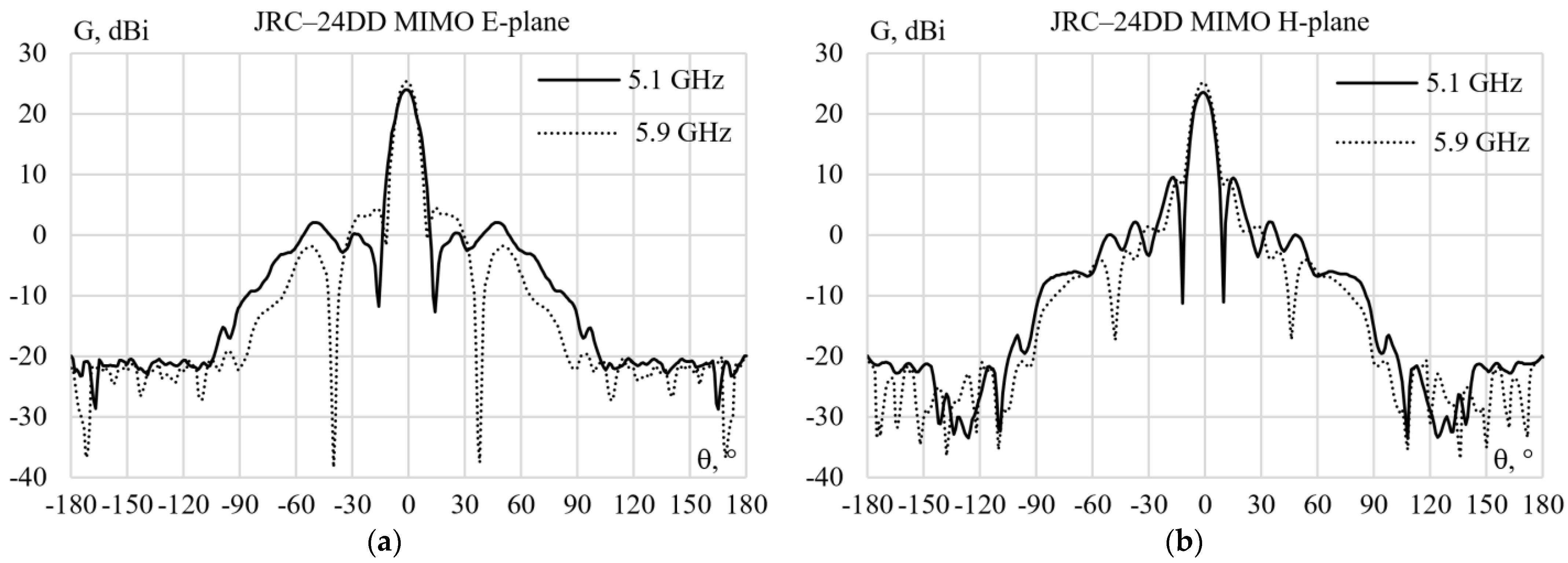
  301. Jirous Antennas Direction for Your Waves. Available online: https://en.jirous.com/antenna-5ghz-parabolic/jrc-24DD_MIMO (accessed on 15 December 2022).
  302. Alhaj Hasan, A.; Klyukin, D.V.; Kvasnikov, A.A.; Komnatnov, M.E.; Kuksenko, S.P. On Wire-Grid Representation for Modeling Symmetrical Antenna Elements. Symmetry 2022, 14, 1354. [Google Scholar] [CrossRef]
  303. Chen, Y.; Wang, C.F. Characteristic Modes: Theory and Applications in Antenna Engineering; John Wiley & Sons: Hoboken, NJ, USA, 2015. [Google Scholar]
Figure 1. “Retranslation” category spacecrafts: Potok (2300 kg) 1982 (a); Luch (2400 kg) 1985 (b); Luch-2 (2420 kg) 1995 (c); Luch-5A (1150 kg) 2011 (d); Luch-5B (1350 kg) 2012 (e); Luch-5V (1150 kg) 2014 (f) [256].
Symmetry 15 00378 g001
Figure 2. Examples of antennas: Precision antenna Ka-band (6.3 kg) (a); double-mirror parabolic Ka-band antenna (10.5 kg) (b); broadband antenna-feeder device (55 kg) (c) [257].
Symmetry 15 00378 g002
Figure 3. Example of an antenna made of composite materials [258].
Symmetry 15 00378 g003
Figure 4. Example of an antenna in the form of a grid of wires as a transformable antenna with gilded wire mesh (mounted on Luch 5A, Luch 5B, and Luch 5V) [259].
Symmetry 15 00378 g004
Figure 5. Actual image of the JRC-24DD MIMO antenna: front side (a); back side of the antenna (b) [301].
Symmetry 15 00378 g005
Figure 6. Measured antenna gain of the JRC-24DD MIMO: E-plane (a) and H-plane (b) at 5.1 GHz and 5.9 GHz [301].
Symmetry 15 00378 g006
Figure 7. Isometric view of the parabolic antenna structure (a); and the wire-grid modeled structure of the parabolic modeled antenna (b).
Symmetry 15 00378 g007
Figure 8. Antenna gain obtained using the wire grid comparing to those measured in [301] in E-plane at 5.1 GHz (a) and 5.9 GHz (b); in H-plane at 5.1 GHz (c) and 5.9 GHz (d).
Symmetry 15 00378 g008
Figure 9. Sparse antenna structures obtained using the general OCGA (sparse) at 5.1 GHz (a) and 5.9 GHz (b) with GEET = 10%; and their gain results compared to those obtained using the wire grid in E-plane at 5.1 GHz (c) and 5.9 GHz (d); and in H-plane at 5.1 GHz (e) and 5.9 GHz (f).
Symmetry 15 00378 g009aSymmetry 15 00378 g009b
Figure 10. Sparse antenna structures obtained using the connected OCGA (sparse) at 5.1 GHz (a) and 5.9 GHz (b) with GEET = 10%; and their gain results compared to those obtained using the wire grid in E-plane at 5.1 GHz (c) and 5.9 GHz (d); and in H-plane at 5.1 GHz (e) and 5.9 GHz (f).
Symmetry 15 00378 g010aSymmetry 15 00378 g010b
Figure 11. Antenna gain at 5.1 GHz obtained using the sparse antenna from the wire-grid structure at 5.9 GHz compared to that obtained using the wire grid (full structure) at 5.1 GHz in E-plane (a) and in H-plane (b) with GEET = 10%.
Symmetry 15 00378 g011
Table 1. Electrical parameters of the antenna [301].
Frequency RangeGainVSWR5.1–5.9 GHzBeamwidth−3 dB
4.9–6.4 GHz24.5 ± 1 dBi≤1.49.0°
Table 2. Mechanical parameters of the antenna [301].
ParabolaInstallation For MastWeight of Antenna
Ø 400 mm, Alluminum alloyØ 27–74 mm2.3 kg (5.1 lbs.)
Disclaimer/Publisher’s Note: The statements, opinions and data contained in all publications are solely those of the individual author(s) and contributor(s) and not of MDPI and/or the editor(s). MDPI and/or the editor(s) disclaim responsibility for any injury to people or property resulting from any ideas, methods, instructions or products referred to in the content.

