Article

On Symmetry and Asymmetry in Nested Electromagnetic Shields

by
Anton A. Ivanov
,
Alexander V. Demakov
,
Maxim E. Komnatnov
and
Talgat R. Gazizov
*
Department of Television and Control, Tomsk State University of Control Systems and Radioelectronics, 634050 Tomsk, Russia
*
Author to whom correspondence should be addressed.
Symmetry 2023, 15(2), 441; https://doi.org/10.3390/sym15020441
Submission received: 29 December 2022 / Revised: 2 February 2023 / Accepted: 3 February 2023 / Published: 7 February 2023
(This article belongs to the Section Physics)

Abstract

:
This work focuses on the study of shield systems consisting of nested enclosures. In the first step, using FDTD simulations and measurements in an anechoic chamber, we investigate the shielding effectiveness (SE) of the system of two nested rectangular enclosures in the frequency range of up to 3 GHz. It is shown for the first time that for a number of frequencies, the SE of the nested shields can be improved by 40–50 dB due to the asymmetric arrangement of the enclosures, their electrical connection, and the mutually perpendicular arrangement of the apertures. Next, we analyze the emissions from the electromagnetic radiation sources in the presence and absence of a nested shield system. The results show that a nested shield system may not attenuate the emission amplitude but increases it by more than 58 dB at the resonant frequencies of the enclosures. Then, we prove that a single enclosure can have a higher SE than the same enclosure as a part of a poorly designed nested shield system. The final part of the article formulates practical recommendations for the design of nested shield configurations.

1. Introduction

Electromagnetic shielding is a well-known and very popular technique for protecting electronic equipment against the influence of radiated emissions. Despite a large number of previous studies, interest in the shielding problem has not subsided to this day. This is confirmed, for example, by a special issue of IEEE Transactions on Electromagnetic Compatibility [1] dedicated to electromagnetic shielding.
In early studies of electromagnetic shields, when the range of operating frequencies of electronic equipment was quite small, the main attention was focused on the analysis of shielding materials [2,3] and the influence of apertures on shielding effectiveness (SE) [4,5,6]. With the progress of electronic technology, operating frequencies have grown to gigahertz ranges, and the electrical size of the equipment has decreased. This made it necessary to consider the shields as cavities that have multiple resonances corresponding to the SE minima. At that time, many methods of shield analysis were proposed [7,8,9,10], new approaches to SE improvement and resonance suppression were developed [11,12,13,14], and it was proved that shields affect the emissions radiated from the equipment placed inside them [15,16,17], etc. In recent years, considerable attention has been paid to the study of shields that take into account their internal filling [18,19,20,21]. New methods of SE measurements [22,23] and calculations [24,25,26,27] have been developed for such structures. Several methods for SE improvement using an internal filling of shields have also been proposed [28,29].
It often happens that a small shielding enclosure can act as a filling of another enclosure [30], resulting in a system of nested shields. Traditionally, “nested” or “multilevel” shielding is considered a good way to provide electromagnetic compatibility [31,32]. However, this statement is true only for low-frequency shielding (outside the resonance region of the shield system) [33,34]. At resonance frequencies, the shielding quality can be compromised by the presence of electromagnetic coupling between the nested shields. Thus, in [35] the authors show that when a resonance is excited in one of several coupled shielding enclosures, the SE of the other enclosure can be reduced by almost 50 dB. In [36], the authors show that the frequency dependence of the voltage induced on a microstrip transmission line located inside nested enclosures has multiple maximums corresponding to the resonant frequencies of both enclosures. Despite the fact that nested shield systems are widely used in real electronic equipment, their research is devoted to an undeservedly small number of works. The aim of this article is to fill this gap.
The rest of this paper is organized as follows. Section 2 describes the shields under study, the simulation technique, and the experimental setup used for measurement. Section 3 presents the results of the SE simulation and measurement for different configurations of the nested shield system consisting of two rectangular enclosures. Section 4 analyzes emissions from electromagnetic radiation sources (half-wave dipoles) when they are located inside the system of nested shields. Section 5 discusses the obtained results and formulates several practical recommendations for the design of nested shield systems. Finally, Section 6 presents conclusions on the work.

2. Materials and Methods

2.1. Simulation and Measurement Techniques

To obtain the results in this work, we used electrodynamic simulation based on the well-established finite-difference time-domain (FDTD) method [37,38,39]. To confirm the simulation results, we used measurements in accordance with the IEEE STD 299 standard.
In all cases under study, a uniform cubic mesh was used in simulation by the FDTD method. The number of cells per wavelength was at least 45. Simulations were performed in the frequency range of 0.3–3 GHz. A perfect electric conductor was used as the material for electromagnetic shields. A plane wave with a unit amplitude of the electric field vector and vertical polarization was used as an excitation in the SE simulations. The SE values were determined as:
SE = 20 log 10 ( | E 0 | / | E | ) ,
where |E| and |E0| are the electric field strength (intensity) in the presence and absence of the shield, respectively. The shields were measured inside a radio-frequency anechoic chamber. The SE values were determined from the modulus of transmission coefficient |S21| between the two antennas using the following formula:
SE = 20 log 10 ( | S 21 0 | / | S 21 | ) ,
where “0” indicates the value of |S21| measured in the absence of the shield.
The transmitting biconical antenna with an operating frequency range from 300 MHz and a maximum measurement error of 1.5 dB was placed at a distance of 1 m from the shield system under study. A quarter-wave monopole with a length of 15 mm was used as a receiving antenna. This length of monopole was chosen to reduce its effect on the resonance frequencies of shields. A Rohde & Schwarz ZNL20 vector network analyzer (VNA) with less than 1 dB measurement error was used to obtain |S21| values. The photo and the schematic diagram of the experimental setup are demonstrated in Figure 1.

2.2. Electromagnetic Shields under Study

In this work, we studied a nested shield system consisting of two rectangular enclosures with apertures (Figure 2a). In all cases, a medium-sized (a1 × b1 × d1 = 300 × 120 × 300 mm3) enclosure from the IEEE STD 1597.2 standard with a square aperture w1 × l1 = 80 × 80 mm2 was used as the external shield of the system. In FDTD simulations, we used a small-sized enclosure (a2 × b2 × d2 = 80 × 40 × 80 mm3) with a square aperture w2 × l2 = 30 × 30 mm2.
For the measurement, shielding enclosures were made of 1.5 mm thick aluminum sheets. The dimensions of the medium-sized enclosure remained the same as in the simulation (Figure 2b). The height b2 of the small-sized enclosure was increased to 80 mm without changing the other dimensions (Figure 2c). This allowed us to reduce the influence of the receiving antenna on the electromagnetic field inside the enclosure and keep TEm0-modes resonance frequencies the same as in the enclosure with a height of 40 mm.

3. Shielding Effectiveness Analysis of Nested Shield System

It is well-known that the SE depends on the size and shape of the shield, its internal filling, and the shape, number, and size of the apertures. However, in nested shield systems, the SE can also be impacted by the electrical connection of the shields and the relative arrangement of the shields and their apertures. This section uses both simulation and measurement techniques to investigate, for the first time, the effect of these factors on the SE of the nested shield system.

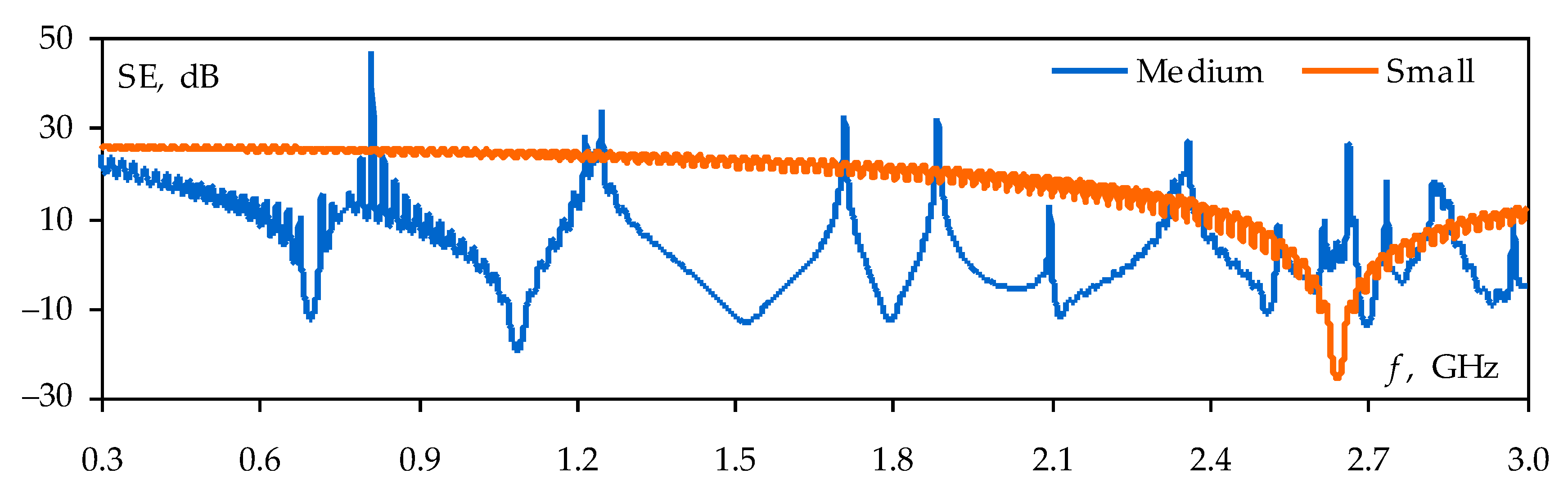
3.1. Simulation of Shield System Elements

Before simulating the shield system using the FDTD method, we calculated the SE for the single enclosures described in Section 2.2. In all cases, observation points were located in the centers of the enclosures. The obtained frequency dependencies of the SE are shown in Figure 3. It can be seen that the SE of an enclosure is complex and can take positive and negative values when the frequency is changed. Negative SE arises when coherent waves with the same phase are combined in the shield, leading to cavity resonances. These resonances are particularly dangerous as the shield can amplify interference at their frequencies. Figure 3 shows that in the frequency range under study in the medium-sized enclosure, there are many resonances in which the SE values become negative. The minimum SE value (minus 20 dB) is observed at the second resonance frequency of 1.1 GHz. In the frequency range under consideration, the small-sized enclosure has only one resonance at a frequency of 2.6 GHz, at which the SE decreases to a level of minus 25 dB.
Figure 3 also shows that both SE frequency dependencies have unphysical oscillations which are caused by the numerical dispersion of the FDTD method. This issue arises from the difference between wave propagation in the actual physical medium and in the discrete FDTD mesh and can be reduced by increasing computational cost [40]. Henceforward, we decided not to eliminate the errors associated with the numerical dispersion since the achieved calculation accuracy is sufficient for this study. This also allowed us to reduce the simulation time and required memory.

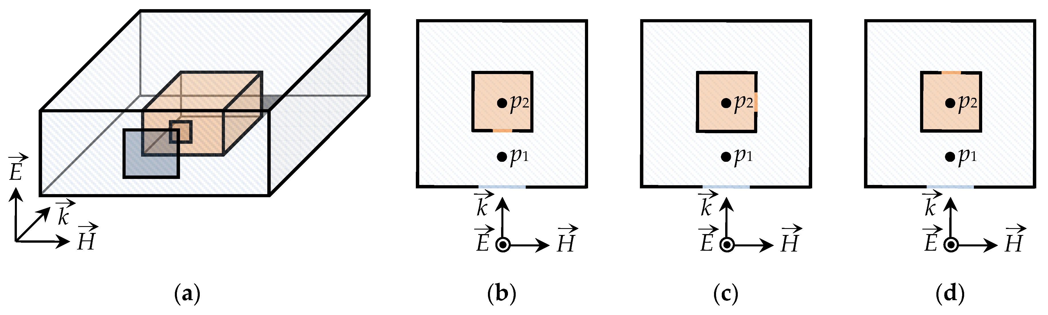
3.2. Changing the Mutual Arrangement of Apertures

In the first step of the study, the shielding enclosures from Section 2.2 were combined into one nested shield system, as illustrated in Figure 4a. Then, using the FDTD method, we evaluated the influence of the mutual arrangement of the apertures in the obtained system on its SE. In the simulation, the small-sized enclosure was arranged symmetrically to the center of the medium-sized enclosure. The aperture arrangement on the medium-sized enclosure and the propagation direction of the plane wave did not change. Three aperture arrangements on the small-sized enclosure were considered: on its front, side, and rear walls (Figure 4b,c). The SE values were determined at two observation points (p1 and p2). Point p2 was located in the center of the small-sized enclosure, and point p1 was located in the medium-sized enclosure at a distance of 50 mm from the center of its aperture.
The results of the SE simulation at observation point p1 are shown in Figure 5. A comparison of Figure 3 and Figure 5 shows that the resonance frequencies of the medium-sized enclosure change when it is populated with the small-sized enclosure. However, changing the aperture arrangement on the small-sized enclosure has almost no effect on the SE at point p1.
The results of the SE calculations at the observation point p2 for the three considered cases of apertures mutual arrangement are shown in Figure 6. It can be seen that cavity resonances excited in the external medium-sized enclosure affect the field in the nested small-sized enclosure and reduce its SE by 5–10 dB at a number of frequencies. It can also be seen that the frequency dependencies of the SE at point p2 change when the aperture of the small-sized enclosure is moved. The worst SE is observed when the aperture of the small-sized enclosure is arranged on its front wall, and the best SE is obtained when the apertures in the system of shields have a mutually perpendicular arrangement. In these two cases, the difference between the SE values reaches 25 dB at 0.3 GHz and 9 dB at the resonance frequency of the small-sized enclosure.

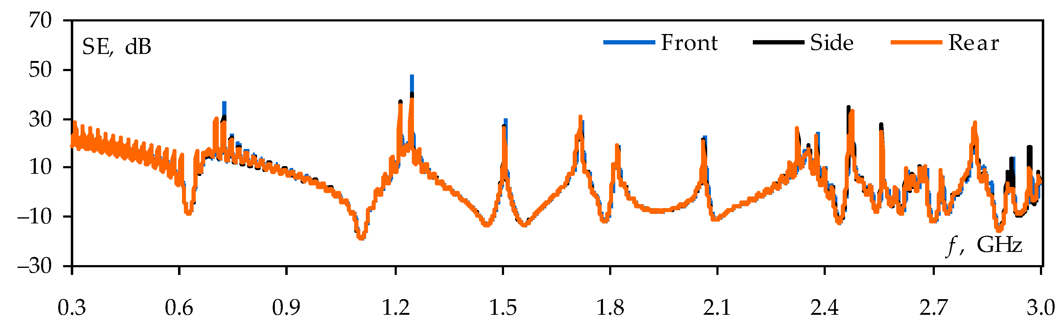
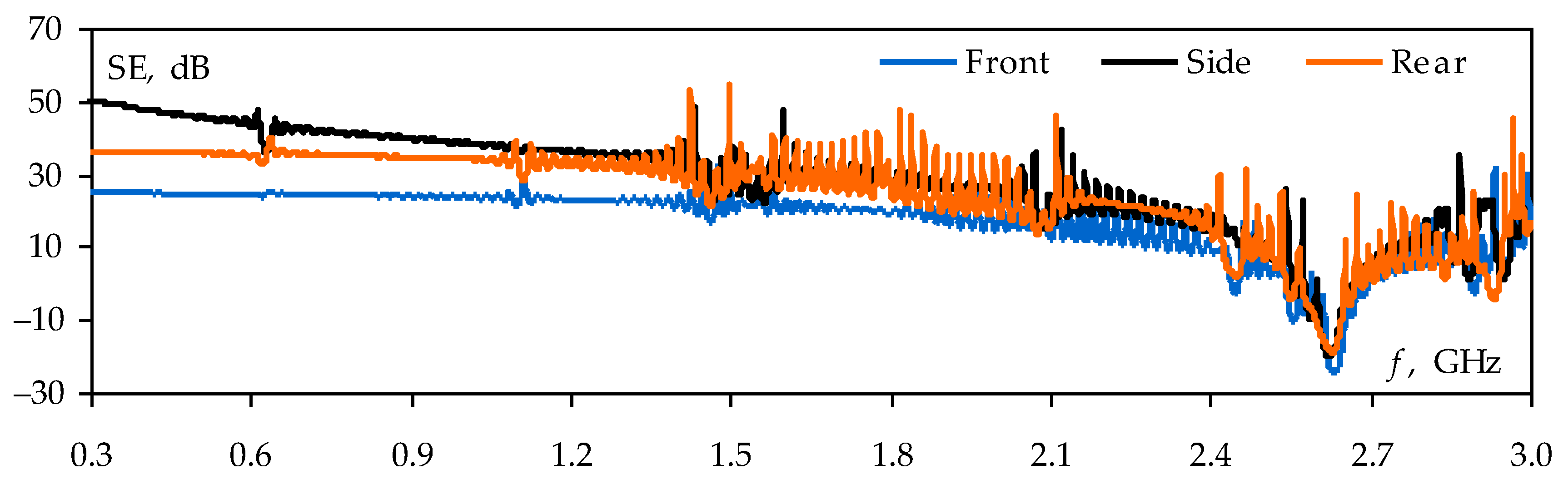
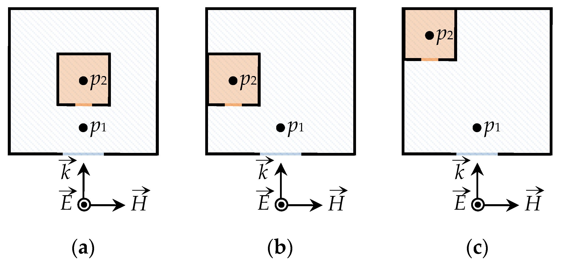
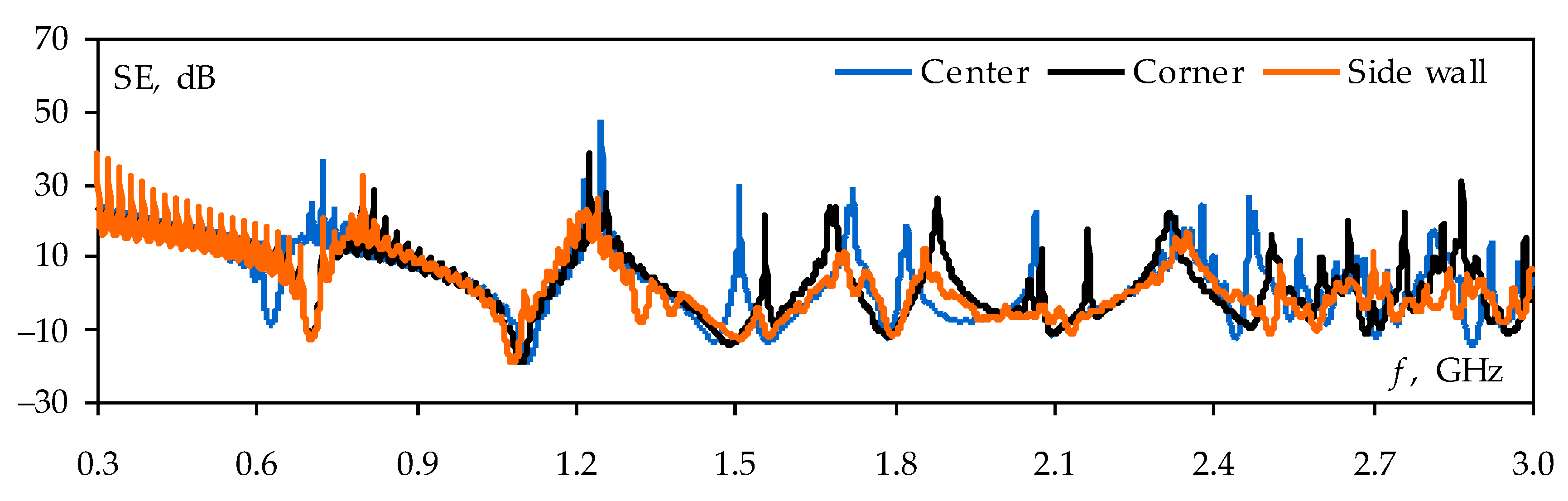
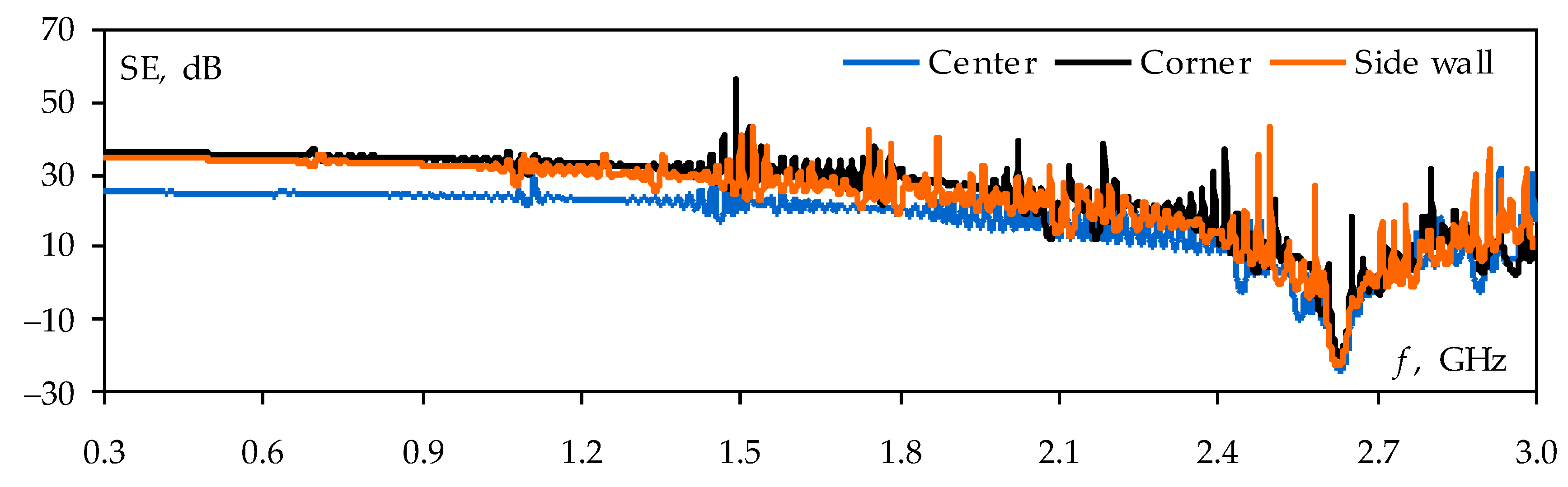
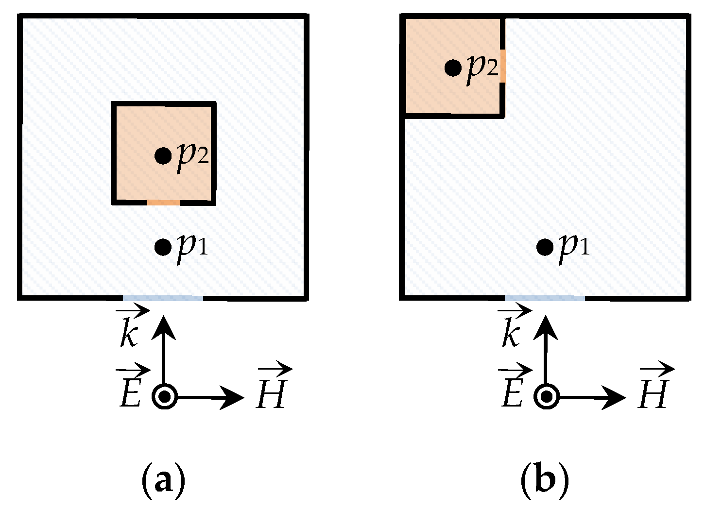
3.3. Influence of the Mutual Arrangement of Enclosures

In the next step of the study, we evaluated the SE of the shield system when the mutual arrangement of the enclosures was changed. In all cases, the apertures of enclosures were opposite each other. The SE observation points remained the same as in Section 3.2. In total, three cases of enclosures mutual arrangement were considered. In the first case, the small-sized enclosure was located symmetrically to the center of the external medium-sized enclosure (Figure 7a), and in the second and third cases, it was placed asymmetrically: at the side wall (Figure 7b) and in the corner (Figure 7c).
The results of the SE calculations at observation point p1 are shown in Figure 8. They demonstrate that changing the arrangement of the nested shields leads to a shift in the resonance frequencies of the medium-sized enclosure, but does not have a strong effect on its SE level.
The frequency dependencies of the SE at the observation point p2 for the three cases of the enclosure arrangement are shown in Figure 9. It can be seen that the small-sized enclosure has the worst SE when the mutual arrangement of the shields is symmetrical. With the asymmetrical arrangement, the SE at point p2 increases by 5–10 dB. Moreover, the SE for the cases in Figure 7b,c differ by only 1.5 dB on average.

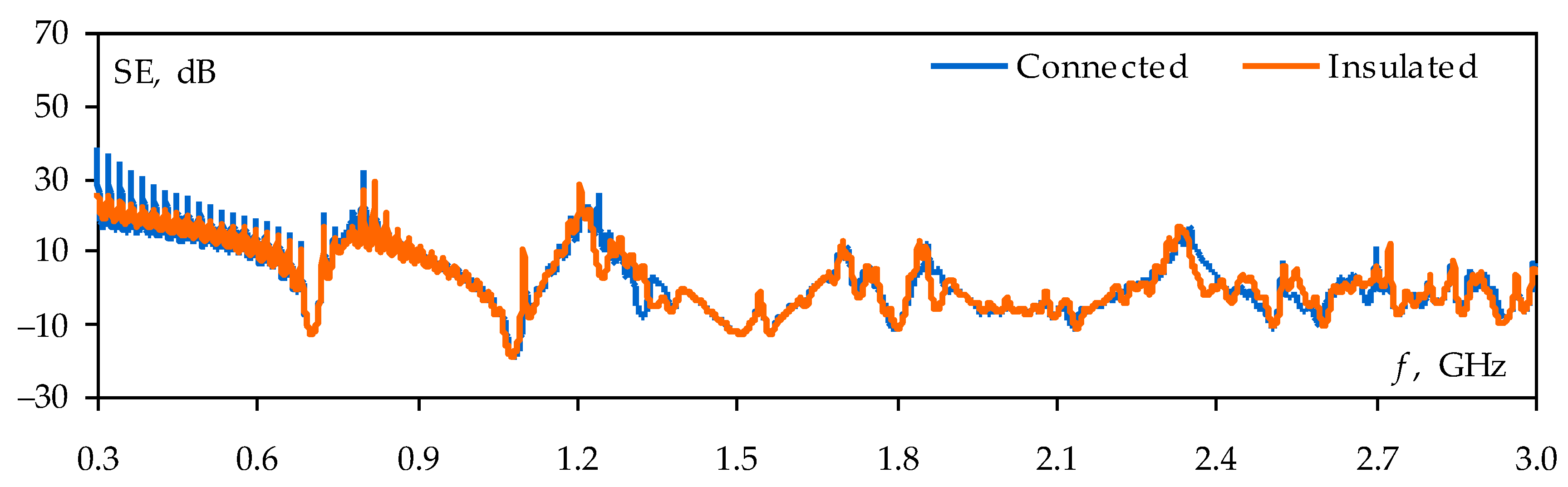
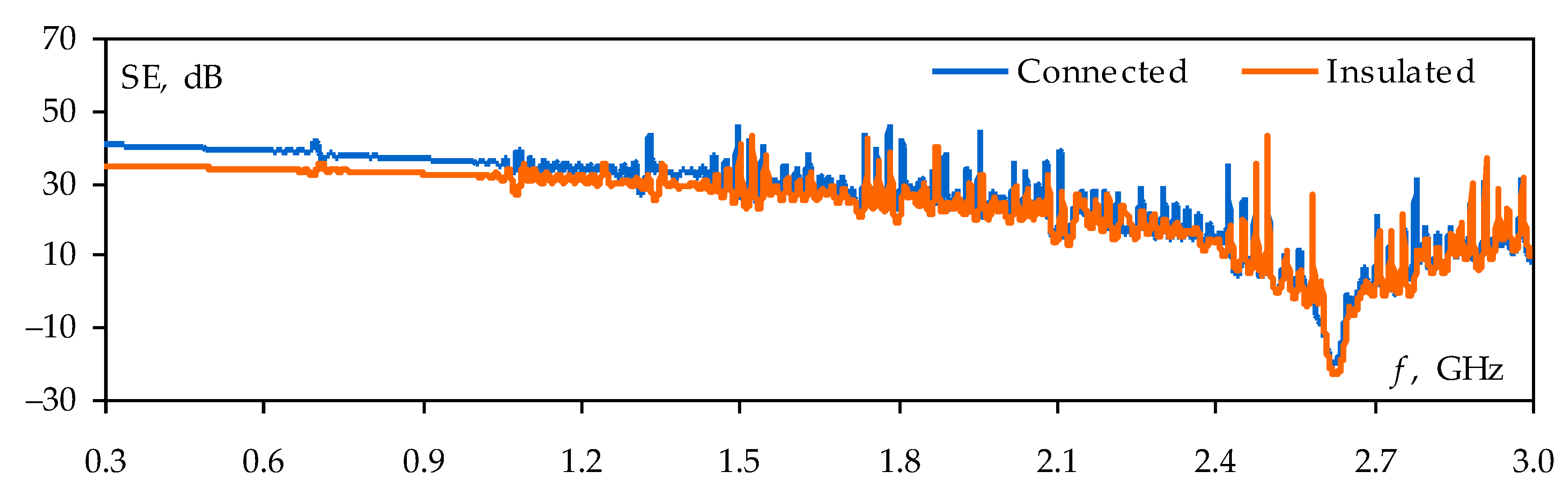
3.4. Insulated or Electrically Connected Enclosures

Next, for the structure in Figure 7b, we evaluated the effect of the enclosure’s electrical connection on the SE of the nested shield system. In the first case, the walls of the enclosures were insulated from each other with a gap of 2 mm, and in the second case, they were electrically connected.
The results of the SE calculations at point p1 inside the medium-sized enclosure are shown in Figure 10. It can be seen that in both cases the SE values are almost the same. At the same time, Figure 11 shows that when the enclosures are electrically connected, the SE at the observation point p2 (inside the small-sized enclosure) is 2–7 dB higher than in the case when the enclosures are insulated. Moreover, the SE values increase the most at frequencies up to 1 GHz.

3.5. Analysis by Measurements

To confirm the above results and conclusions, we measured the SE of the nested shield system using the experimental setup from Section 2.1 (see Figure 12). The receiving antenna was placed only inside the small-sized enclosure because in all simulation cases, the SE of the external medium-sized enclosure changed insignificantly.
The measured frequency dependencies of the SE inside the small-sized enclosure are shown in Figure 13. The measurement confirms that the SE of a nested shield can be improved by the asymmetric arrangement of the enclosures, their electrical connection, and the mutually perpendicular arrangement of the apertures.

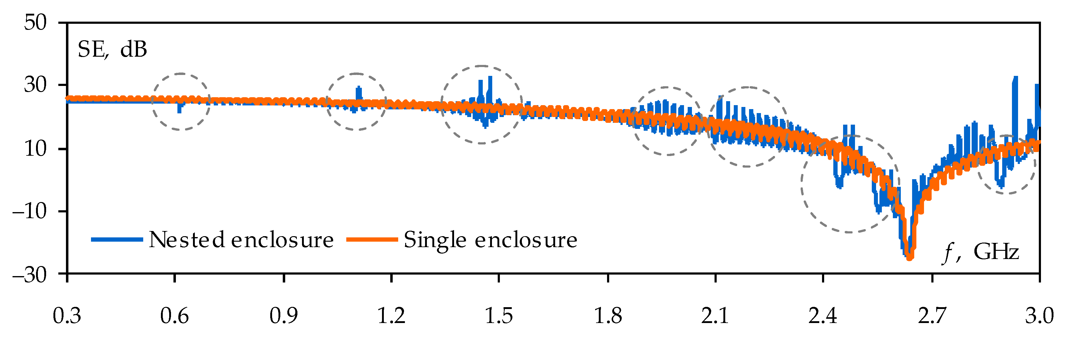
3.6. Comparison of the «Best» and «Worst» Cases

Given the results obtained above, two nested shield systems were formed, corresponding to the “worst” and “best” cases for shielding. In the “worst” case (Figure 14a), the enclosures were insulated and symmetrically arranged, and the apertures were opposite each other. In the “best” case (Figure 14b), the shields were electrically connected, the small-sized enclosure was arranged in the corner of the medium-sized enclosure, and the apertures were mutually perpendicular.
For these two systems, we calculated the frequency dependencies of the SE inside the medium-sized (point p1) and small-sized (point p2) enclosures. The results of the calculations are shown in Figure 15.
The calculation results from Figure 15a show that in the “best” shield system the first resonance of the medium-sized enclosure is excited 100 MHz higher than in the “worst” system. This leads to the improvement of the SE at low frequencies. In the “best” case, the medium-sized enclosure also has a higher level of SE at frequencies between 2.4 GHz and 3 GHz (by 1.5 dB on average).
Figure 15b shows that the SE of the small-sized enclosure in the “best” system is significantly greater than in the “worst” one. Thus, at some frequencies, the increase in the SE is 40–50 dB. Moreover, in the “best” system of shields, the small-sized enclosure has positive values of the SE in the whole frequency range under study. In both cases, the lowest SE values were obtained at a frequency of 2.6 GHz, corresponding to the resonance of the small-sized enclosure. These values are 4.5 dB and minus 24 dB for the “best” and “worst” cases, respectively.

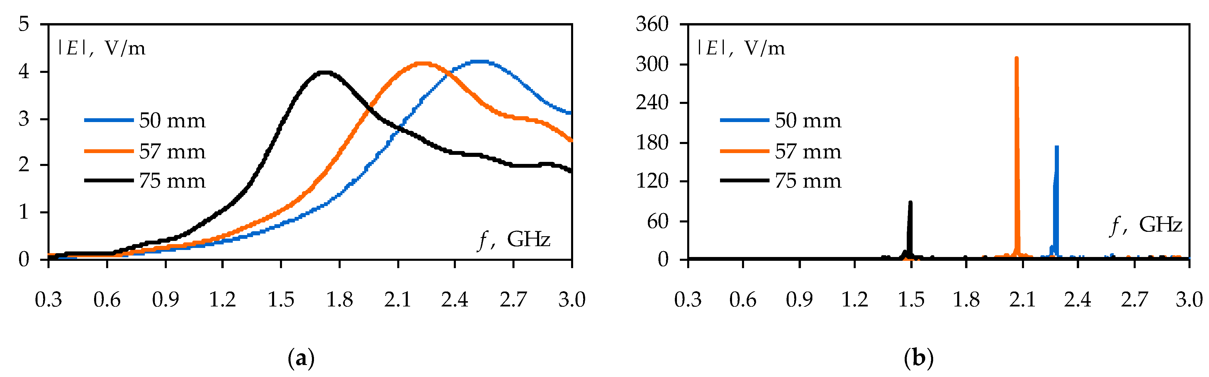
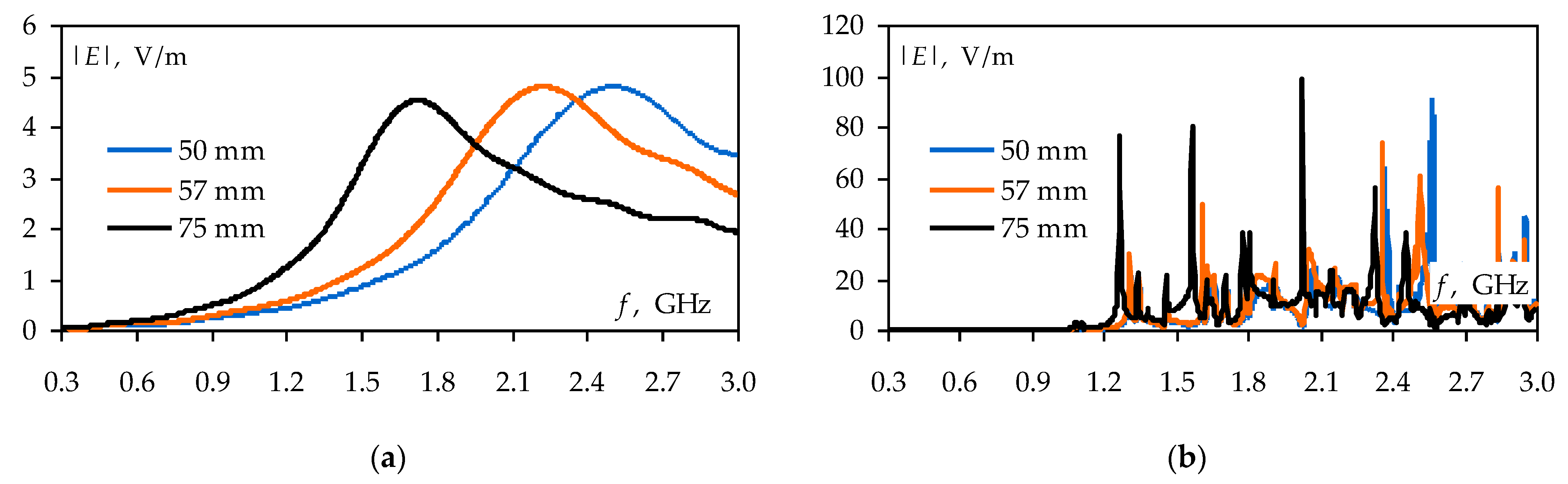
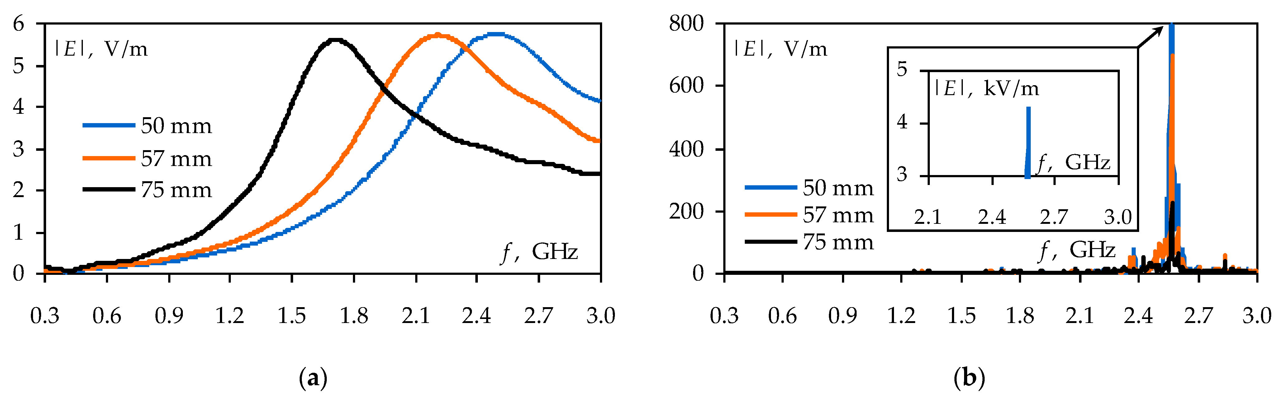
4. Radiated Emissions

It is well-known that emissions from an electromagnetic radiation source located inside the enclosure can be significantly altered by enclosure resonances. However, radiated emissions in nested shield systems have yet to be extensively investigated. In this section, we aim to thoroughly evaluate the impact of the radiation source position and operating frequency range on the emissions in a nested shield system.

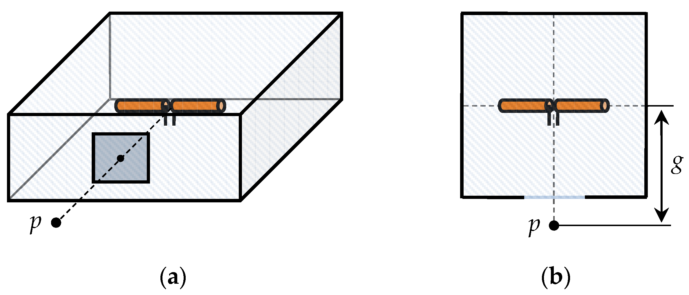
4.1. Radiation Sources

This part of the study was devoted to the analysis of emissions from the sources of electromagnetic radiation when they are located in a shield system consisting of two rectangular enclosures. Symmetrical half-wave dipoles with lengths L of 50 mm, 57 mm, and 75 mm were used as radiation sources (Figure 16a). The dipole sizes L = 50 mm and L = 75 mm were chosen because their resonance frequencies coincide with the resonances of the small-sized and medium-sized enclosures, respectively (Figure 16b). A dipole of length L = 57 mm with a resonance frequency of 2.34 GHz was used to investigate the emission at frequencies different from the resonance frequencies of the nested shield system. All studies were performed using the FDTD method. The dipole antennas were excited by an ideal 1 V voltage source with zero internal resistance. In all cases, the emission level was evaluated from the electric field strength modulus |E| in the presence and absence of shields.

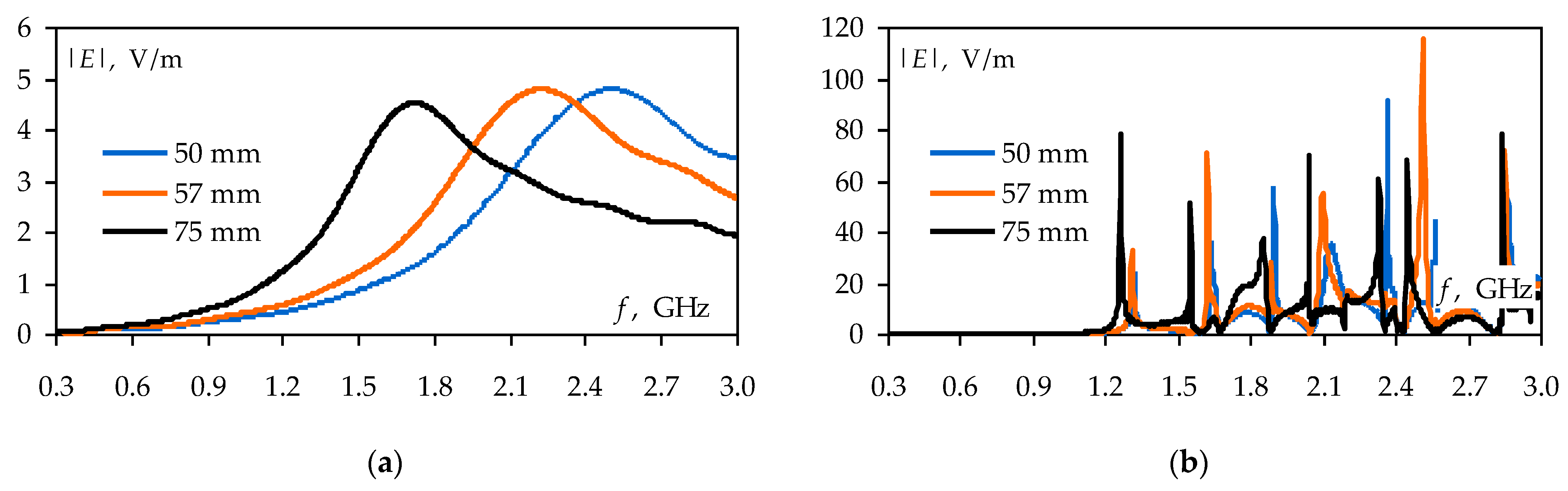
4.2. Emissions in Single Enclosures

First of all, we simulated the emissions from the dipole antennas when they were placed in each of the small-sized and medium-sized enclosures. In both cases, the dipoles were placed in the center of the enclosures. The observation points of an emissions level were located opposite the apertures at a distance of 50 mm (Figure 17). Thus, when we simulated emissions in the small-sized enclosure, the distance g between the source and the observation point was 90 mm. For the medium-sized enclosure, g was taken as 200 mm.
Figure 18 shows the results of the |E| calculation at a distance of 90 mm from the dipoles in the presence and absence of the small-sized enclosure. It can be seen that in the absence of the enclosure, the |E| level does not exceed 9 V/m for all dipoles under study. When the dipoles are located inside the enclosure, the maximum values of the |E| increase significantly. The greatest increase in the emission level (21.4 times or 26.6 dB) is observed for the dipole with L = 50 mm, whose operating frequencies coincided with the resonance frequency of the enclosure. Figure 18b also shows that the frequencies of the |E| maximums do not coincide with the resonances of the enclosure or dipoles, which may be related to the antenna’s influence on the structure of the electromagnetic field inside the enclosure.
Figure 19 shows the frequency dependencies of |E| at a distance of 200 mm from the dipoles, calculated in the presence and absence of the medium-sized enclosure. It can be seen that in the absence of the enclosure, the maximum values of the |E| do not exceed 5 V/m. The emission level increases due to cavity resonances inside the enclosure. The maximum value of |E| is obtained at a frequency of 2.5 GHz and is 115 V/m. This value was obtained by excitation of a dipole with a length of 57 mm whose operating frequencies do not coincide with the enclosure resonances.

4.3. Emissions in the System of Nested Enclosures

Further, we simulated emissions in a nested shield system. The small-size enclosure was arranged in the corner of the medium-sized enclosure. The enclosures were electrically insulated, and the apertures were opposite each other. We considered two cases of dipole antenna placement inside the shield system. In the first case (Figure 20a), the dipoles were placed in the center of the small-sized enclosure. The observation points p1 and p2 were placed inside and outside the medium-sized enclosure at equal distances of 50 mm from its aperture. In the second case (Figure 20b), the dipoles were located in the center of the medium-sized enclosure. Point p1 remained the same as in Figure 15a, while point p2 was placed in the center of the small-sized enclosure. We also calculated frequency dependencies of |E| in the absence of shields but with the same locations of dipoles and observation points.
Figure 21 shows the results of the |E| calculation at the observation point p1 for the structure from Figure 20a in the absence and presence of the shields. It can be seen that the maximum value of |E| at point p1 without the shield system does not exceed 3.5 V/m. When the nested shield system is added, the emission level increases significantly. Thus, the maximum value of |E| is 218 V/m for a dipole with L = 57 mm. It is interesting that the frequencies of the |E| maximums in Figure 21b coincide with Figure 18b, while the maximum values of |E| are observed at different dipole lengths. This may be due to the influence of medium-sized enclosure resonances on the radiation sources.
Figure 22 shows the frequency dependencies of |E| at the observation point p2 for the structure from Figure 20a in the absence and presence of the shield system. It can be seen that in the absence of the shield system, the maximum emission level does not exceed 4.2 V/m, otherwise |E| increases to 307 V/m. Comparing Figure 21b and Figure 22b, we can see that in the E-field range under consideration, emissions at points p1 and p2 have a similar character and differ only in the amplitudes of the maximums.
Figure 23 illustrates the results of calculating |E| at the observation point p1 for the structure from Figure 20b in the absence and presence of the shields. The maximum |E| level in Figure 23a is 4.5 V/m, and in Figure 23b it is 99 V/m. The results show that when the dipole antenna is placed in the medium-sized enclosure, the frequency dependence of |E| has many maximums, not one, as in the shield system from Figure 20a. It can also be seen that the emissions obtained here and earlier in Figure 19b for a single medium-sized enclosure are quite similar, but differ slightly in the frequencies of maximums. This can be explained by the influence of the small-sized enclosure on the structure of the electromagnetic field inside the medium-sized enclosure.
Finally, Figure 24 shows the frequency dependencies of |E| at the observation point p2 for the structure from Figure 20b with and without nested shields. The obtained results demonstrate that in the absence of shields, the maximum level of emissions does not exceed 5.5 V/m, and in their presence increases very strongly. Thus, when the dipole length is equal to 50 mm at a frequency of 2.6 GHz (the resonance of the small-sized enclosure), the |E| value exceeds 4.3 kV/m. In this case, the nested shield system amplifies the emissions by more than 780 times, or 58 dB. When the length of the dipole antenna increases, the maximum |E| value decreases, and at L = 50 mm, it reaches 0.2 kV/m. Figure 24b also shows several additional maximums of |E| (e.g., at 2.38 GHz and 2.85 GHz) at which the emission levels are 60–90 V/m.

5. Discussion

The results in Section 3 demonstrate that a well-designed system of nested shields can have a sufficiently high SE level and provide the necessary interference immunity of electronic equipment. At the same time, if the system is poorly designed, the use of “nested” shielding does not give any positive effect, and even partially worsens the SE of a single enclosure. As an example, let us compare the frequency dependencies of the SE from Figure 3 and Figure 15b for the system of two nested shields and the single small-sized enclosure (Figure 25). The comparison shows that the single small-sized enclosure and the same enclosure as a part of a poorly designed system have generally similar SE values. However, in several frequency regions (highlighted by circles in Figure 25), an enclosure in a shield system has a lower SE than a single enclosure. This effect is due to the resonances of the external medium-sized enclosure in the nested shield system.
In addition, the results obtained in Section 4 prove that in some cases “multilevel” shielding of the interference source can be a very poor way of ensuring electromagnetic compatibility. If the nested shield system is poorly designed, the enclosures have strong electromagnetic coupling, and their resonance frequencies roughly coincide with the interference frequencies, both enclosures will simultaneously amplify the interference. This can lead to the situation obtained in Figure 24b where the initial level of electromagnetic interference was amplified by the shield system by more than 780 times, or 58 dB.
We formulated several practical recommendations for the design of nested shield systems that can help prevent the problematic situations described above.
  • Try to avoid a symmetrical mutual arrangement of nested shields. It is best to arrange the small enclosure on the side wall of the external enclosure or in its corner.
  • Try to avoid counter arrangement of the apertures in a nested shield system. SE can be slightly increased by arranging the apertures mutually perpendicular.
  • Try to electrically connect the nested enclosures to improve SE. This method should be used carefully, as poorly designed electrical connections can produce reactive elements that unpredictably change the resonance frequencies of the shield system.
  • Try to size the shields so that their resonances do not coincide with interference frequencies. This will allow you to avoid increasing the level of electronic equipment emissions. If you cannot select the necessary shield sizes, the resonance frequencies of the shields can be shifted by using conductive plates [25] or posts [28].
  • Try to use a standard approach that involves reducing aperture sizes in order to reduce electromagnetic coupling in the nested shield system. At resonance frequencies, electromagnetic coupling between nested shields can be reduced by using radar-absorbing materials [20], lossy dielectrics [19], or band-stop frequency selective structures [29].

6. Conclusions

In this work, we have investigated a shield system consisting of two nested enclosures. First, using the FDTD method and measurements in an anechoic chamber, the SE of different configurations of nested enclosures have been evaluated. As a result, it was demonstrated for the first time that the SE of the nested shield system can be improved by their asymmetric arrangement, electrical connection, or mutually perpendicular arrangement of the apertures. Further, the emission from electromagnetic radiation sources in the form of half-wave dipoles has been investigated when they are located in the system of nested shields and in free space. It was shown that the locations of dipoles and observation points inside the shield system strongly affect the level of radiated emissions. It was also illustrated that nested shield systems may not attenuate the emission amplitude, but increase it (by more than 58 dB). Finally, it has been shown that a single enclosure can have better SE than the same enclosure as a part of a poorly designed nested shield system. Summarizing the obtained results, several practical recommendations for the design of nested shield systems have been formulated.
Although this work reveals some aspects of the nested shield design, such shields still have a lot of potential for research. First of all, in future studies, we would like to evaluate how the electromagnetic coupling between enclosures behaves in systems consisting of three or more nested shields. The study of nested shields with regard to their internal filling is also of interest, because, as noted in the introduction, the filling can have a strong effect on the structure of the electromagnetic field inside the shields.

Author Contributions

Conceptualization and methodology, M.E.K.; investigation, A.A.I. and A.V.D.; writing—original draft preparation, A.A.I.; writing—review and editing, T.R.G. All authors have read and agreed to the published version of the manuscript.

Funding

The modeling was financially supported by the Ministry of Science and Higher Education of the Russian Federation (Project FEWM-2022-0001). The simulation and measurements were carried out at the expense of Russian Science Foundation grant 19-79-10162.

Data Availability Statement

The data presented in this study are available on request from the corresponding au-thor. The data are not publicly available due to the funding organization policy.

Conflicts of Interest

The authors declare no conflict of interest.

References

  1. Celozzi, S.; Chiu, C.-N. Editorial introduction to the special issue on advances and perspectives in EM shielding and absorbers. IEEE Trans. Electromagn. Compat. 2022, 64, 1550–1551. [Google Scholar] [CrossRef]
  2. Schulz, R.B.; Plantz, V.C.; Brush, D.R. Shielding theory and practice. IEEE Trans. Electromagn. Compat. 1988, 30, 187–201. [Google Scholar] [CrossRef]
  3. Casey, K.F. Electromagnetic shielding behavior of wire-mesh screens. IEEE Trans. Electromagn. Compat. 1988, 30, 298–306. [Google Scholar] [CrossRef]
  4. Otoshi, T.Y. A study of microwave leakage through perforated flat plates. IEEE Trans. Microw. Theory Techn. 1972, 20, 235–236. [Google Scholar] [CrossRef]
  5. Mendez, H.A. Shielding theory of enclosures with apertures. IEEE Trans. Electromagn. Compat. 1978, EMC-20, 296–305. [Google Scholar] [CrossRef]
  6. Vitek, C. Predicting the shielding effectiveness of rectangular apertures. In Proceedings of the National Symposium on Electromagnetic Compatibility, Denver, CO, USA, 23–25 May 1989; pp. 27–32. [Google Scholar]
  7. Hill, D.A.; Ma, M.T.; Ondrejka, A.R.; Riddle, B.F.; Crawford, M.L.; Johnk, R.T. Aperture excitation of electrically large, lossy cavities. IEEE Trans. Electromagn. Compat. 1994, 36, 169–178. [Google Scholar] [CrossRef]
  8. Robinson, M.P.; Benson, T.M.; Christopoulos, C.; Dawson, J.F.; Ganley, M.D.; Marvin, A.C.; Porter, S.J.; Thomas, D.W.P. Analytical formulation for the shielding effectiveness of enclosures with apertures. IEEE Trans. Electromagn. Compat. 1998, 40, 240–248. [Google Scholar] [CrossRef]
  9. Flintoft, I.D.; Whyman, N.L.; Dawson, J.F.; Konefal, T. A fast and accurate intermediate level modelling approach for electromagnetic compatibility analysis of enclosures. In Proceedings of the 4th International Conference on Computation in Electromagnetics, Bournemouth, UK, 8–11 April 2002; pp. 1–2. [Google Scholar]
  10. Solin, J.R. Formula for the field excited in a rectangular cavity with a small aperture. IEEE Trans. Electromagn. Compat. 2011, 53, 82–90. [Google Scholar] [CrossRef]
  11. Azizi, H.; Tahar Belkacem, F.; Moussaoui, D.; Moulai, H.; Bendaoud, A.; Bensetti, M. Electromagnetic interference from shielding effectiveness of a rectangular enclosure with apertures—Circuital approach, FDTD and FIT modelling. J. Electromagn. Waves Appl. 2014, 28, 494–514. [Google Scholar] [CrossRef]
  12. Wu, G.; Zhang, X.-G.; Song, Z.-Q.; Liu, B. Analysis on shielding performance of metallic rectangular cascaded enclosure with apertures. Prog. Electromagn. Res. Lett. 2011, 20, 185–195. [Google Scholar] [CrossRef] [Green Version]
  13. Vaezikakhki, S.; Mosavinejad, S.S.; Bahadorzadeh, M. Study the effect of different parameters and improving the shielding effectiveness of a metallic enclosure with extra wall. J. Electr. Comput. Eng. 2019, 3, 53–57. [Google Scholar] [CrossRef]
  14. Bahadorzadeh, M.; Lotfi, A. A novel and efficient technique for improving shielding effectiveness of a rectangular enclosure using optimized aperture load. Electron. Electr. Eng. 2012, 18, 89–92. [Google Scholar] [CrossRef]
  15. Cerri, G.; De Leo, R.; Primiani, V.M. Theoretical and experimental evaluation of the electromagnetic radiation from apertures in shielded enclosure. IEEE Trans. Electromagn. Compat. 1992, 34, 423–432. [Google Scholar] [CrossRef]
  16. Li, M.; Nuebel, J.; Drewniak, J.L.; DuBroff, R.E.; Hubing, T.H.; van Doren, T.P. EMI from cavity modes of shielding enclosures-FDTD modeling and measurements. IEEE Trans. Electromagn. Compat. 2000, 42, 29–38. [Google Scholar]
  17. Nie, X.C.; Yuan, N.; Li, L.W.; Gan, Y.B. Accurate modeling of monopole antennas in shielded enclosures with apertures. Prog. Electromagn. Res. M 2008, 79, 251–262. [Google Scholar] [CrossRef]
  18. Maftooli, H.; Sadeghi, S.H.H.; Karami, H.; Dehkhoda, P.; Moini, R. An efficient time-domain integral solution for a loaded rectangular metallic enclosure with apertures. IEEE Trans. Electromagn. Compat. 2016, 58, 1064–1071. [Google Scholar] [CrossRef]
  19. Ghandehari, M.B.; Khazaei, A.; Vaezi, S. A novel method to eliminate the resonance of a rectangular enclosure with aperture. Int. J. Appl. Electromagn. Mech. 2016, 50, 215–224. [Google Scholar] [CrossRef]
  20. Kwon, J.H.; Hyoung, C.H.; Hwang, J.-H.; Park, H.H. Impact of absorbers on the shielding effectiveness of metallic rooms with apertures. Electronics 2021, 10, 237. [Google Scholar] [CrossRef]
  21. Rusiecki, A.; Aniserowicz, K. Evaluation of shielding effectiveness of slotted enclosures by internal stirring. In Proceedings of the 20th International Conference on Microwaves, Radar and Wireless Communications (MIKON), Gdansk, Poland, 16–18 June 2014; pp. 1–4. [Google Scholar]
  22. Rusiecki, A.; Aniserowicz, K.; Orlandi, A.; Duffy, A.P. Internal stirring: An approach to approximate evaluation of shielding effectiveness of small slotted enclosures. IET Sci. Meas. Technol. 2016, 10, 659–664. [Google Scholar] [CrossRef]
  23. Flintoft, I.D.; Bale, S.J.; Marvin, A.C.; Ye, M.; Dawson, J.F.; Wan, C.; Zhang, M.; Parker, S.L.; Robinson, M.P. Representative contents design for shielding enclosure qualification from 2 to 20 GHz. IEEE Trans. Electromagn. Compat. 2018, 60, 173–181. [Google Scholar] [CrossRef]
  24. Li, F.; Han, J.; Zhang, C. Study on the influence of PCB parameters on the shielding effectiveness of metal cavity with holes. In Proceedings of the IEEE 3rd Information Technology, Networking, Electronic and Automation Control Conference (ITNEC), Chengdu, China, 15–17 March 2019; pp. 383–387. [Google Scholar]
  25. Ivanov, A.A.; Komnatnov, M.E.; Gazizov, T.R. Analytical model for evaluating shielding effectiveness of an enclosure populated with conducting plates. IEEE Trans. Electromagn. Compat. 2021, 62, 2307–2310. [Google Scholar] [CrossRef]
  26. Chen, K.; Gao, M.; Liu, S.; Wang, Y.; Zhou, X.; Chen, T. A circuit model for predicting the shielding effectiveness of cylindrical enclosure. Meas. Sci. Technol. 2022, 33, 115006. [Google Scholar] [CrossRef]
  27. Marvin, A.C.; Parker, S.L.; Dawson, J.F.; Robinson, M.P. Measurements and power balance calculations of the shielding effectiveness of partitioned equipment enclosures. In Proceedings of the International Symposium on Electromagnetic Compatibility, Barcelona, Spain, 2–6 September 2019; pp. 158–162. [Google Scholar]
  28. Hussain, T.; Majid, I.; Cao, Q. Measurements improved shielding effectiveness of enclosures using symmetrically placed metallic posts. In Proceedings of the International Bhurban Conference on Applied Sciences and Technology (IBCAST), Islamabad, Pakistan, 14–18 January 2020; pp. 679–685. [Google Scholar]
  29. Chan, H.W.; Wu, R.B. A novel desensitization using resonance suppressors in metallic shielding. IEEE Trans. Compon. Packag. Manuf. Technol. 2019, 9, 1680–1689. [Google Scholar] [CrossRef]
  30. Razavi, S.M.J.; Khalaj-Amirhosseini, M. Investigation of electromagnetic shielding rooms with metal cabinet and aperture. Prog. Electromagn. Res. M 2010, 12, 181–192. [Google Scholar] [CrossRef]
  31. Lehr, J.; Pralhad, R. EM Topology for Interference Control. In Foundations of Pulsed Power Technology; John Wiley & Sons, Inc.: Hoboken, NJ, USA, 2017; Volume 12, pp. 585–608. [Google Scholar]
  32. Ing, E.; Armstrong, K.; Eng, C. EMC Techniques in Electronic Design Part 4—Shielding (Screening); Cherry Clough Consultants: Stafford, UK, 2009. [Google Scholar]
  33. Rajawat, R.K.; Kalghatgi, R.S.; Ron, P.H. Measurements and analysis of transient electromagnetic shielding effectiveness for nested shield configurations. In Proceedings of the 1995 International Conference on Electromagnetic Interference and Compatibility (INCEMIC), Chennai, India, 6–8 December 1995; pp. 153–160. [Google Scholar]
  34. Kistenmacher, P.; Schwab, A. Low-frequency shielding effectiveness of inhomogeneous enclosures. In Proceedings of the 1996 IEEE International Symposium on Electromagnetic Compatibility (EMC), Santa Clara, CA, USA, 19–23 August 1996; pp. 347–352. [Google Scholar]
  35. Shen, W.; Wang, S.; Li, W.; Jin, H.; Zhang, H. An extended hybrid analytical model for shielding effectiveness prediction of multi-cavity structure with numerous apertures. Prog. Electromagn. Res. M 2020, 96, 181–190. [Google Scholar] [CrossRef]
  36. Xiao, P.; Du, P.-A.; Ren, D.; Nie, B.-L. A hybrid method for calculating the coupling to PCB inside a nested shielding enclosure based on electromagnetic topology. IEEE Trans. Electromagn. Compat. 2016, 58, 1701–1709. [Google Scholar] [CrossRef]
  37. Li, M.; Ma, K.-P.; Hockanson, D.M.; Drewniak, J.L.; Hubing, T.H.; Van Doren, T.P. Numerical and experimental corroboration of an FDTD thin-slot model for slots near corners of shielding enclosures. IEEE Tras. Electromagn. Compat. 1997, 39, 225–232. [Google Scholar]
  38. Jiao, C.; Li, L.; Cui, X.; Li, H. Subcell FDTD analysis of shielding effectiveness of a thin-walled enclosure with an aperture. IEEE Trans. Magn. 2006, 42, 1075–1078. [Google Scholar] [CrossRef]
  39. Mai, H.; Chen, J.; Zhang, A. A hybrid algorithm based on FDTD and HIE-FDTD methods for simulating shielding enclosure. IEEE Trans. Electromagn. Compat. 2018, 60, 1393–1399. [Google Scholar] [CrossRef]
  40. Cheng, Y.; Chen, G.; Wang, X.-H.; Yang, S. Investigation of numerical dispersion with time step of the FDTD methods: Avoiding erroneous conclusions. IET Microw. Antennas Propag. 2021, 15, 691–703. [Google Scholar] [CrossRef]
Figure 1. Photo (a) and schematic diagram (b) of the experimental setup.
Symmetry 15 00441 g001
Figure 2. Geometry of rectangular enclosure (a); shielding enclosures used for measurements: 300 × 120 × 300 mm3 (b), and 80 × 80 × 80 mm3 (c).
Symmetry 15 00441 g002
Figure 3. Frequency dependencies of the SE for medium-sized (300 × 120 × 300 mm3) and small-sized (80 × 40 × 80 mm3) enclosures.
Symmetry 15 00441 g003
Figure 4. Isometric view of the nested shield system (a) and its top views when the aperture of the small-sized enclosure is located on its front (b), side (c), and rear (d) walls.
Symmetry 15 00441 g004
Figure 5. Frequency dependencies of the SE at the observation point p1 when the aperture of the small-sized enclosure is located on its front, side, and rear walls.
Symmetry 15 00441 g005
Figure 6. Frequency dependencies of the SE at the observation point p2 when the aperture of the small-sized enclosure is located on its front, side, and rear walls.
Symmetry 15 00441 g006
Figure 7. Top views of the nested shield system at different arrangements of the small-sized enclosure: in the center (a); on the side (b); and in the corner (c).
Symmetry 15 00441 g007
Figure 8. Frequency dependencies of the SE at the observation point p1 when the mutual arrangement of enclosures is changed.
Symmetry 15 00441 g008
Figure 9. Frequency dependencies of the SE at the observation point p2 when the mutual arrangement of enclosures is changed.
Symmetry 15 00441 g009
Figure 10. Frequency dependencies of the SE at the observation point p1 when enclosures are insulated or electrically connected.
Symmetry 15 00441 g010
Figure 11. Frequency dependencies of the SE at the observation point p2 when enclosures are insulated and electrically connected.
Symmetry 15 00441 g011
Figure 12. System of nested shields in the anechoic chamber.
Symmetry 15 00441 g012
Figure 13. Measured frequency dependencies of the SE for the nested small-size enclosure: changing the enclosure arrangement (a), the orientation of the apertures (b), and the method of electrical connection (c).
Symmetry 15 00441 g013aSymmetry 15 00441 g013b
Figure 14. Top views of the nested shield system: the “worst” (a) and “best” (b) cases for shielding.
Symmetry 15 00441 g014
Figure 15. Frequency dependencies of the SE for the “worst” and “best” nested shield systems at observation points p1 (a) and p2 (b).
Symmetry 15 00441 g015
Figure 16. Symmetrical half-wave dipole model with a feed gap (a) and frequency dependencies of the reflection coefficient modulus |S11| for dipoles with different lengths (b).
Symmetry 15 00441 g016
Figure 17. Isometric (a) and top (b) views of enclosures populated with a half-wave dipole.
Symmetry 15 00441 g017
Figure 18. Frequency dependencies of |E| at a distance g = 90 mm from the dipoles in the absence (a) and presence (b) of the small-sized enclosure.
Symmetry 15 00441 g018
Figure 19. Frequency dependencies of |E| at a distance g = 200 mm from the dipoles in the absence (a) and presence (b) of the medium-sized enclosure.
Symmetry 15 00441 g019
Figure 20. System of nested shields with a half-wave dipole located inside the small-sized (a) or medium-sized (b) enclosures.
Symmetry 15 00441 g020
Figure 21. Frequency dependencies of |E| at point p1 for the structure from Figure 20a in the absence (a) and presence (b) of the shield system.
Symmetry 15 00441 g021
Figure 22. Frequency dependencies of |E| at point p2 for the structure from Figure 15a in the absence (a) and presence (b) of the shield system.
Symmetry 15 00441 g022
Figure 23. Frequency dependencies of |E| at point p1 for the structure from Figure 15b in the absence (a) and presence (b) of the shield system.
Symmetry 15 00441 g023
Figure 24. Frequency dependencies of |E| at point p2 for the structure from Figure 15b in the absence (a) and presence (b) of the shield system.
Symmetry 15 00441 g024
Figure 25. Frequency dependencies of the SE for the single small-sized enclosure and the same enclosure as a part of the nested shield system. Circles indicate deterioration of the SE values.
Symmetry 15 00441 g025
Disclaimer/Publisher’s Note: The statements, opinions and data contained in all publications are solely those of the individual author(s) and contributor(s) and not of MDPI and/or the editor(s). MDPI and/or the editor(s) disclaim responsibility for any injury to people or property resulting from any ideas, methods, instructions or products referred to in the content.

