1. Introduction
The principles of the theory of elasticity lead to inherent symmetries in the associated elasticity tensor, which defines any linearly elastic continuum at a given position. Furthermore, an elasticity tensor may display additional context-specific symmetries. This study focuses on these later symmetries, sometimes known as “material symmetries”. When symmetry is involved, it can be found in the bifurcation theory, physics, and the mechanics of materials when constituent tensors, such as the elastic tensor, require classification. Moreover, several formulas for coordination-free criteria for determining elastic tensors with a given symmetry class can be found in the literature, complementing experimental and numerical techniques.
There are always new developments in nanoelectromechanical systems research and development. Mechanical devices are becoming thinner and narrower to lessen their mass, raise their resonance frequency, and decrease their force constants. Improvements in manufacturing procedures and the development of novel techniques for actuating and sensing nanoscale motion are examples of recent developments in this area [
1]. Microelectromechanical systems (MEMS) are one of the most critical technologies of the 21st century. It combines silicon-based microelectronics and micro industry, two of the most advanced technologies. Its microsystem-based methods and technologies may improve the overall quality of human life.
Because MEMS is a combination of many different fields, its design, construction, and manufacturing depend on mechanical design, solid-state physics, microelectronics, biological sciences, chemical engineering, hydrodynamic engineering, optical devices, sensor systems, and packaging. The variety of industries and uses that employ MEMS indicates its sophistication. Accelerometers for airbag sensors are one example of an MEMS device that is made and used commercially [
2]. In today’s world, microelectromechanical systems can be found in everything from automobiles to healthcare, electronics, communications, and even military systems. Li et al. [
3] studied the nonlinear in-plane instability of shallow circular arches made of functionally graded carbon nanotube-reinforced composite that were limited by rotational symmetry and put under constant radial stress in a temperature environment. Li [
4] is also interested in the transverse vibrations of axially moving nanobeams. This is in addition to the effects of the strain gradient and temperature. It considers the thermal behavior and the concept of strain gradient elasticity. Li et al. [
5] investigated the motion of a piezoelectric nanoribbon under the influence of thermomechanical and electrical forces. This is employed as a model for the intrinsic component of medical nanorobotics. Sui et al. [
6] described the vibrational properties of axially moving, fairly thick plates supported by an elastic base. The plate is made of functionally graded (FG) materials, and both its dynamic and kinematic conditions including the vibration’s inherent frequency and axial velocity are taken into consideration. Zemskov et al. [
7] discussed the issue of unstable vibrations in a Bernoulli–Euler beam while considering temperature and diffusion processes that relax with time. The first mathematical model comprises an equation set for the beam’s unstable bending vibrations that consider heat transfer and mass transfer.
In civil engineering, rigid road slabs, airport asphalt, tall building foundations, sidewalk platforms, etc., are often made with flexible-based composite structures. In these cases, it is important to consider the mechanical properties of structures mounted on an elastic base, as they are important considerations for design, use, and maintenance. For this reason, one of the most exciting areas of research in this field has been the analysis of the vibration response of laminated slabs and small beams supported by flexible foundations. Based on the literature in this context, there are two main types of flexible baseboard models: the Winkler type and the two-parameter models, such as the Pasternak model [
8].
Winkler proposed the first linear foundation. Many papers have been written about this issue, exploring various approaches such as Winkler or Pasternak foundations, flexible or viscoelastic foundations, linear or non-linear assumptions, etc. In contrast to the Pasternak foundation coefficients, which can withstand both normal and transverse shear stresses, the Winkler modulus can only handle normal loads [
9]. The two-parameter elastic foundation model is presented as the investigation proceeds further. The discontinuity may be efficiently removed by representing the soil’s compressive strength and shear strength with two separate factors, thereby overcoming the shortcomings of the Winkler foundation type. The Pasternak basis is commonly employed in the two-parameter type [
10]. Zemskov and Tarlakovskii [
11] considered an orthotropic Timoshenko beam with a uniformly distributed transverse load, rests on an elastic base, and is supported by an elastic base. The problem is one of unstable elastic diffusion resonance. On a flexible basis, they employed the Winkler framework. For the theoretical analysis, they employed a set of Timoshenko beam bending formulas that include diffusion. Zemskov et al. [
12] studied the issue of unstable vibrations in a simply supported Euler–Bernoulli beam subject to a distributed transverse force. They employ a set of beam deflection formulas with inner diffusion processes to formulate the mathematical issue.
Joule heating is often used as a trigger mechanism in microelectromechanical systems (MEMS) because it is easy to understand. The term “joule heating” refers to the process by which the electrical current of a building is converted into heat energy. In order to regulate the axial tension caused by thermal expansion from within the microbeam, a VTH electrothermal voltage (thermoelectric potential) is introduced between the microbeam stabilizers, causing an ITH current to flow through the beam, but the permanent anchors of the microbeam, which cause a compressive force, prevent any elongation from occurring. The microbeam might buckle (deform) under such compressive stress. There are two ways to approach the study of this mechanism: the thermoelectric case, which explains the conversion of electrical energy into heat, and the thermoelasticity case, which accounts for the conversion of thermal energy into compressive stress [
13]. Joule heating is produced when an electric current flows through a conductor and interacts with the moving particles that make up the current and the atomic ions that make up the conductor itself. When these particles, which make up the electric current, collide with an ion, they lose some of their momentum in the process. This kinetic energy makes the conductor’s internal temperature rise, which turns the electrical energy into thermal energy [
14].
In recent decades, researchers have paid particular attention to innovative, continuous models of deformable materials. It is known that the internal structural motions of matter play an important role in determining how matter interacts with external stimuli. Conventional flexibility completely ignores this effect because it only gives degrees of freedom in translation to physical locations in the body. In thermoelasticity, the interplay between elasticity and heat transfer is analyzed theoretically. Thermal stresses and thermoelastic deformations in a variety of materials have been the focus of a great deal of research in recent decades [
15]. Researchers are exploring thermoelasticity because of its usefulness in many different branches of engineering and science. The thermoelastic phenomenon is briefly discussed in light of different computational techniques. When solving heat transfer issues using thermoelasticity theory, the outcomes vary depending on the starting and limiting conditions [
16].
Based on Biot’s system of mixed parabolic and hyperbolic Biot equations [
17], conventional thermodynamic models predict some physical observations and outcomes that contradict physical phenomena. These observations include the infinite velocities of the thermal signals. That is why many researchers have revised the concept of traditional coupled dynamic thermoelasticity in this context to address this problem. The majority of proposals are based on the development of the classic Fourier law of heat transfer. Among these proposed thermal models are those that include periods of thermal relaxation (thermal delay time). In recent years, Lord and Shulman [
18], Green and Lindsay [
19], and Green and Naghdi [
20,
21,
22] have published different modified heat transfer models. These systems are the hyperbolic heat equations that have received the most attention in the literature.
From a mathematical and computational point of view, the individual physical phenomena that make up many linked issues are well explained and sophisticated models that can be used to describe their mathematical representation. On the other hand, there are some situations in which a new model is necessary. This is because the current standard concept for discussing certain physical processes has been shown to be insufficient, and it can even sometimes lead to contradictions within some well-established physical systems. In these situations, a new framework is formulated. In this study, the Moore–Gibson–Thompson (MGT) equation will be used to figure out how heat moves in a thermoelastic system. This model emerges due to the insertion of a relaxation parameter into the Green–Naghdi type III framework [
23]. Quintanilla [
24] presented a thermoelastic model in which the MGT equation includes the heat transfer rate. In this context, Quintanilla [
16] also proposed a two-temperature system for the Moore–Gibson–Thompson heat transfer equation. In previous embodiments, Quintanilla has shown that solutions are well-rendered and fade exponentially when the constituent parameters are set correctly. Since the advent of the MGT equation theory of thermoelasticity in the field of fluids, many studies have been conducted on this topic [
25,
26,
27,
28,
29,
30,
31,
32].
In many engineering applications, optimal design requires performing the elastic thermal vibration analysis of microbeams on an elastic basis. However, no solutions have been developed for the thermoelastic vibration issues that arise when thermal coupling is included in analyses of such structures resting on three-parameter viscoelastic elastic bases. For this purpose, the investigation of how the Winkler and Pasternak foundations affect the thermoelastic behavior of an Euler–Bernoulli beam is proposed. In order to achieve this, it was necessary to solve the derived differential equation that governs this system in order to obtain the distributions of various physical domains. Moreover, the generalized heat transfer equation has been modified based on the MGT equation and is considered the first proposal in this field. Using a three-parameter viscoelastic basis and taking into account the thermoelastic coupling effect, the thermoelastic behaviors of microbeam resonators were studied as a result of the effects of the initial axial tension, the effects of the laser pulse, and the voltage. Finally, the numerical results of the different fields obtained are presented graphically and discussed in detail.
2. Theoretical Analysis and Basic Equations
In the theory of thermoelasticity of homogeneous conductive solids for heat transfer, the following set of governing equations can be written [
33]:
In these equations, denotes the strain tensor, is the stress tensor, represents the displacement components, symbolizes the entropy, denotes the heat flow components, signifies the heat source, is the specific heat, represents the Kronecker delta, and is the material density. The symbols and are the usual Lame’s constants, , and is the thermal expansion coefficient. Additionally, is the temperature increment, where is the reference temperature.
The revised version of Fourier’s Law that is in line with the GN-III context [
21] may be written as:
where
symbolizes the thermal displacement,
refers to the material characteristics,
is the thermal conductivity, and
.
The suggested improved heat equation was developed by Quintanilla [
15,
16] after the relaxation coefficient
was implemented into the Green–Naghdi framework of type III. Therefore, the resulting revised heat transfer equation will be in the form of [
23,
24]:
A modified MGT heat transfer equation is obtained by combining Equations (2), (4), and (6) as follows:
3. Model Description
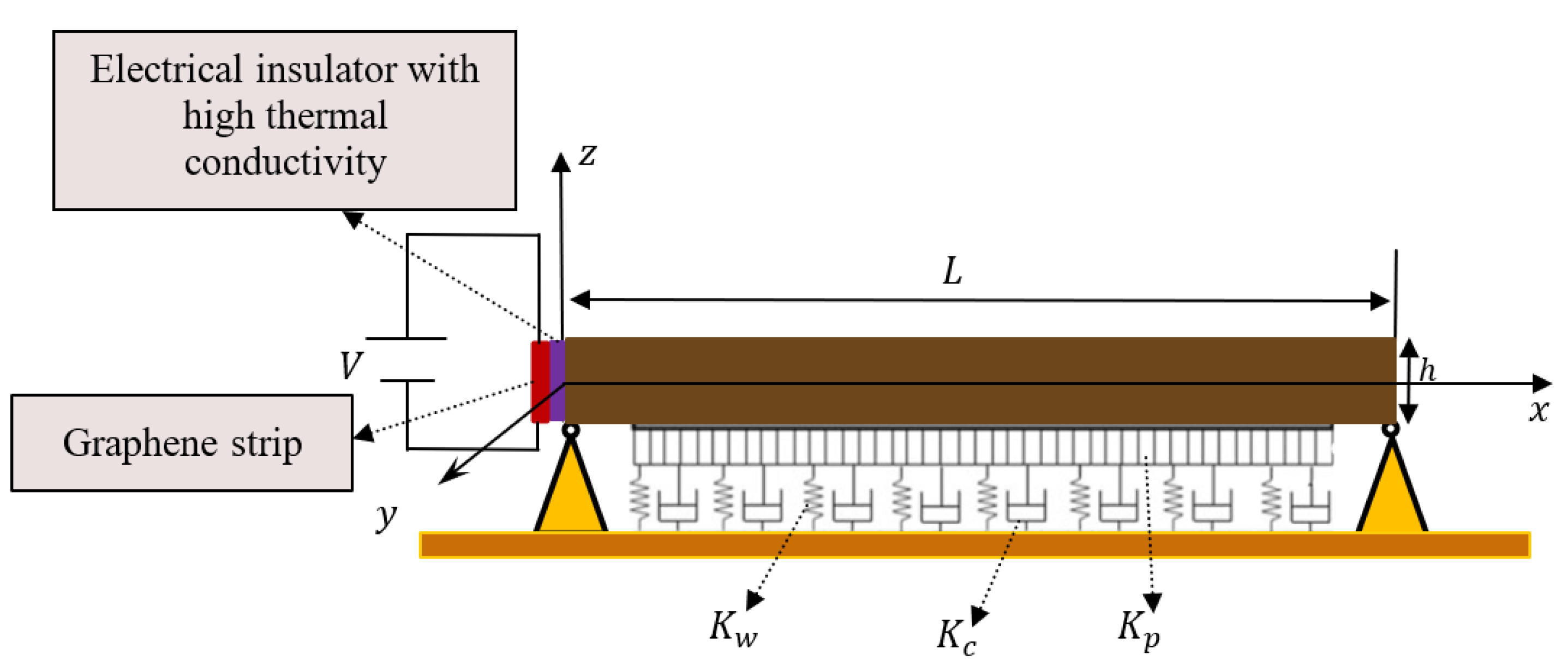
As illustrated in
Figure 1, a thin Bernoulli–Euler thermoelastic beam supported by a viscoelastic foundation with three parameters and loaded with a thermoelectric current was considered. The microbeam has an isotropic shape with a constant cross-sectional area, denoted by
, thickness
, and length, denoted by
. It is presumed that a Cartesian coordinate system
is being used, with the origin located on the left side of the beam and in the middle of its thickness. The microbeam is first assumed to be at room temperature
, and then it is exposed to a short-pulse laser heating at an absorption rate of
of laser energy.
It is assumed that the beam deflects in a manner consistent with the Euler–Bernoulli model (small deflections
) as a result of its exposure to bending vibrations of small amplitude around
-axis. If the Euler–Bernoulli beam model is considered, the displacement and strain components can be written as follows:
Pasternak’s model has been utilized to characterize the soil foundation so that shear contact between the springs may be calculated. To do this, the spring components will be joined to a layer of incompressible vertical elements that are subject only to transverse shear deformation. Because of its relative ease of use, Pasternak’s two-parameter system has garnered the most attention from engineers. The impact of the underappreciated shear–strain energy on the soil is taken into consideration in the Pasternak version. Pasternak’s basis formula, which is based on transverse displacement, forms an elastic reaction to the foundation and is as follows [
33,
34]:
where the Winkler and Pasternak moduli are denoted by the parameters
and
, respectively.
In order to account for the effects of viscoelasticity, Kelvin–Voigt included them in the elastic Pasternak model. The elastic foundation force can be expressed as [
34]:
where
represents the damping of the foundation caused by the viscous components. In the special situation where
is equal to zero, Equation (11) depicts the reaction of the viscoelastic Winkler foundation. If the microbeam is not supported by the elastic basis, then
, and Equation (11) may be simplified to become that which is described in [
35].
For the Bernoulli–Euler microbeam shown in
Figure 1, the linear bending issue may be represented by the following equation of motion in terms of the Pasternak’s basis,
, and the bending moment,
[
36,
37]:
It is possible to calculate the Bernoulli–Euler flexural moment of the microbeam using the following equation
where
is the single constitutive connection for a one-dimensional problem, and the expression for this relationship is provided by:
In Equation (14),
,
, and
denote Young’s modulus, the coefficient of the thermal expansion, and Poisson’s beam ratio, respectively. When (14) is substituted into (13), the flexural moment can be derived as follows:
where
,
represents the moment of inertia,
stands for the flexural stiffness of the microbeam, and
is the thermal moment described by the expression:
By plugging Equation (15) into Equation (12), it is possible to derive:
When Equations (7) and (8) are used, one can determine the MGT heat transport in terms of temperature
and transverse displacement
as follows:
It will be considered that the upper and lower sides of the package are thermally insulated. As a result, we will have
at
. Additionally, for the current microbeam, it is presumed that the temperature increase varies sinusoidally in the direction of the thickness. Therefore, the following assumption can be taken into account:
When Equation (19) is substituted into Equations (15) and (17), the resulting equations are:
Following the multiplication by
, the integration, together with the microbeam thickness in Equation (18), produces the following results:
5. Initial and Boundary Conditions
In the beginning, at
, the microbeam is taken to be at rest, and the initial circumstances are supposed to be:
Boundary conditions are necessary to ensure the possibility of a complete solution to the system of differential equations. In this work, the following mechanical boundary conditions will be taken into account
Joule heating is produced when an electric current flows through a conductor and interacts with the moving particles that make up the current and the atomic ions that make up the conductor itself. When these particles, which make up the electrical current, collide with an ion, they lose some momentum. This kinetic energy causes the conductor’s internal temperature to increase, which changes the electrical energy into thermal energy. When a potential voltage is applied across the first end of a microbeam (
), heat is generated with an intensity per volume of
, where
is the current density described by
, and
is the electrical conductivity of the microbeam. The density of the current is considered to remain constant all along the microbeam. Due to the small scale of the investigation, it will be assumed that convection and thermal radiation from the microbeam are restricted and negligible. The average temperature along the portion of the microbeam caused by the current
is governed by the following equation, which is derived using the heat equation (Fourier’s law) and the aforementioned assumptions [
14]:
The electrothermal voltage
and current density may be expressed as
. Since this is the case, Equation (31) may be rewritten as [
14]:
In addition, it will be assumed that at the second terminal edge of the microbeam, the function
satisfies the following condition
6. Laplace Transform Solution
The partial differential equation in the time domain may be transformed into a differential equation in the space domain with the help of a mathematical method known as the Laplace transform. After that, the result is transformed using the inverse Laplace operator on the response, which causes it to be translated back into the time domain. If
is a function that operates in the time domain, then the mathematical definition of its Laplace transform is given by:
Now, by taking the beginning conditions (29) and applying the Laplace transform to both sides of the basic equations given in (24)–(27), the following formulas can be obtained:
where
Combining Equations (35) and (36) results in the differential equation shown below:
where
It is possible to write the differential Equation (36) as follows:
where the roots of the equation:
are satisfied by the parameters
,
.
The solution to Equation (52) can be expressed as follows:
where
.
By using the conditions of the issue, it is possible to derive the values for the parameters
and
, where
in Equation (44). Similarly, by removing the function
from Equations (35) and (36), the following equation can be arrived at:
where
.
It is possible to write the solution of Equation (45) as:
where:
With the assistance of Equations (44) and (46), one can construct the solution for the variables
,
, and
in the Laplace domain as follows:
The boundary conditions (30) to (33) imposed on the problem can be transformed into the domain of the Laplace transform to become:
Boundary conditions (49) are inserted with Equations (40) and (42) to yield:
By solving this system of linear equation, the values of the two unknown parameters and , where can be determined.
8. Numerical Results and Analysis
To depict the thermo-dynamic behavior of the thin microbeam on the viscous Pasternak basis with a heat supply in the form of laser pulses, an analytical and numerical solution was derived in the preceding sections, taking into consideration the thermoelectric influence. In the present section, the analytical results obtained from the literature will be reviewed, and the effects of several essential elements and parameters on the variations of the considered field variables, such as nondimensional temperature and deflection, will be examined. The current approach suffers from a lack of actual empirical cases, which can be used to measure the physical domains being investigated and then compare them to others.
As far as the authors are aware, there has been no previous research into the thermomechanical consequences of analyzing vibration in a thermoelectric beam using the generalized theory of thermoelasticity. For this reason, the present article uses general thermoplastic models to consider the vibrational properties of a microbial beam based on a viscoelastic-Pasternak base. To determine how to solve this problem, relevant theoretical issues will be considered, along with how the results are similar and different. Here, the numerical findings of a silicon-doped microbeam will be presented, considering the physical parameters listed in
Table 1.
Due to the application of non-dimensional values in the problem, it will be assumed that
and
in the numerical calculations. The results are graphically shown in
Figure 2,
Figure 3,
Figure 4,
Figure 5,
Figure 6,
Figure 7,
Figure 8,
Figure 9,
Figure 10 and
Figure 11 and
Table 2, with values ranging from 0 to 1.0 at different
-coordinates. Based on the analytical solutions obtained previously, numerous numerical examples were presented to study how the visco-foundation Pasternak indices (shear stiffness
, damping modulus of the foundation
, and horizontal spring stiffness
) affect the beam response under the influence of the thermoelectric heat flow. Simulation results are also used to look at how the rise time of the laser
and the electrothermal voltage coefficient
affect the temperature of the microbeam and how it bends. This is completed to better understand the thermoelectric phenomena.
8.1. The Influence of Visco-Pasternak’s Basis Factors
In this subsection, the numerical results of the different field variables for studying the vibration of thermoelectric microbeams and evaluating their temperature
, deformation
, and deflection
will be presented, taking into account the changes in the nondimensional visco-Pasternak flexible basis factors (
,
, and
).
Table 2 shows how the coefficients
,
, and
affect the thermomechanical properties of the microbeam. The researchers used a modified version of the MGT heat transfer equation so that they could study the different variations and give facts and figures for each. In order to make comparisons, the non-dimensional values
,
,
,
= 10, and
can be set. It can be seen that the results can be obtained from comprehensive thermoplastic calculations for beams without a visco-Pasternak elastic basis by setting
.
The numerical data in
Table 2 illustrates the influence of the Pasternak parameter (shear stiffness)
on the values of various domains as a function of distance. One can see that as the shear stiffness
increases, so do the values of the deflection
in this table. The numerical data show that increasing the constant base factors mitigates the effects of the Winkler and Pasternak coefficients
and
on the deflection
. This is because a more rigid microbeam system is inherently stronger.
Table 2 displays the relationship between deflection and the Winkler stiffness modulus
. Moreover, in
Table 2, the studied domains are represented against the distance for a variety of viscous damping coefficient values (
). As the damping coefficient
rises, the physical fields become increasingly noticeable. This is expected due to the fact that linear deviation is proportional to
.
The table shows that the absolute values of the nondimensional thermal stress , as well as the bending moment , increased with the increase in the Winkler stiffness parameter () and Pasternak () coefficients. The precision girder stability is enhanced as a result of the increased structural rigidity in and . Changes in the visco-Pasternak basis profoundly affect the bending moment and the deflection within the microbeam. Variations in the coefficients of the Pasternak viscous basis have less effect on the deformation and temperature .
It is seen from the numerical values in the table that the quantities of the different thermophysical fields decline when the Winkler and Pasternak coefficients and remain unchanged with the increase in the viscous damping coefficient . In addition, when there is a change in the viscous damping parameter , there is little variation in the temperature and displacement values. The absolute value of the deviation w increases as the viscosity parameter decreases. As the viscous damping modulus and other exponents are increased, the dimensionless axial stress and flexure moment increase.
It has been observed that increasing the viscoelastic structural damping parameter of microscale beams can reduce the internal thermophysical fields. The reason for this is that a rise in the structural damping coefficient causes the structure to be less rigid. The influence of the viscous structural damping parameter is more pronounced when the Winkler and Pasternak parameters and remain unchanged. This review article can provide useful information for the design of some fine structural systems by helping to choose the appropriate foundation model, which must take into account the stability, control, and vibrations of the structural system being treated or designed. As a consequence of the analysis mentioned above, it is clear that the anticipated results will be on the low side for the problem if shear stiffness, damping, or transverse impact are ignored. Engineering that considers these factors will produce better results at a lower cost.
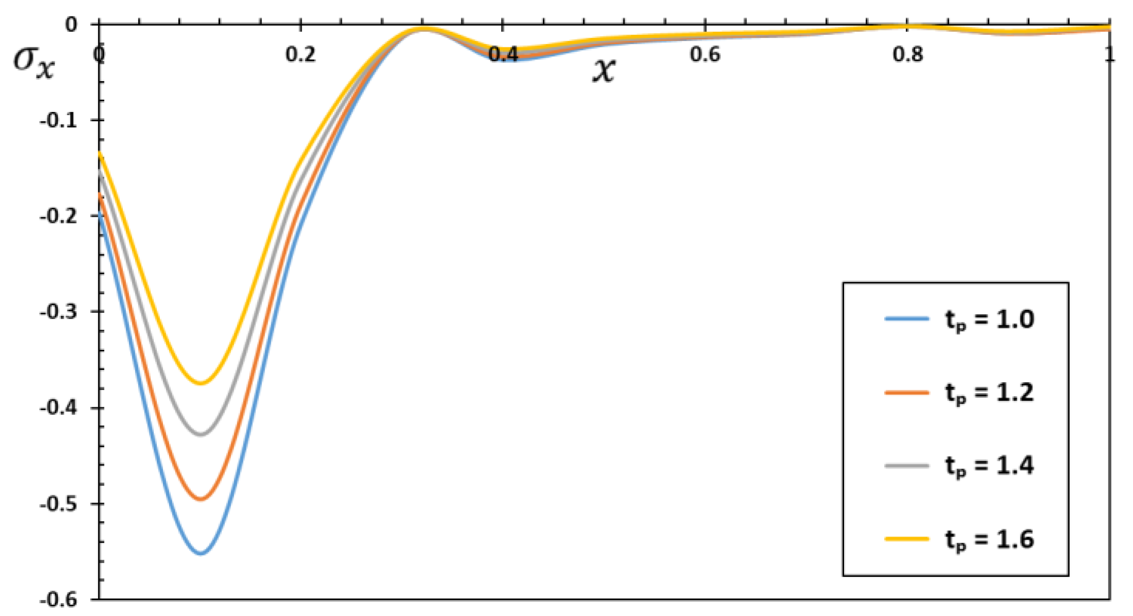
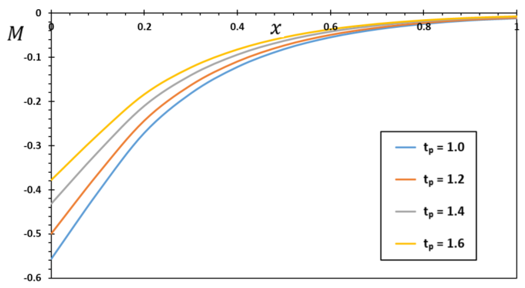
8.2. Effect of Laser Pulse Duration
This present work studied the transient electrical and thermal conductivity in thin silicon bundles subjected to short-pulse laser heating as a heat source by means of the MGT thermal conductivity model. Exciting the metal with an ultrafast laser can cause the material to enter a state very different from its original equilibrium. A system of cold, highly bound ions immersed in a partially degenerated electron sea is produced due to the preferential and rapid heating of one subsystem compared to another. These temporary states frequently occur during the formation of high-energy-density plasmas, which can contain warm, dense matter. These cases are particularly relevant for laser micromachine fusion studies and self-entrapment fusion studies because of their transient nature. In the laboratory, these short-lived states are used to test quantum mechanics theories of nuclear dynamics, electron-ion interactions, and phase transitions.
It is very important to study the thermal influence that a non-Gaussian laser has on thermoelastic microbeams when using a laser as a heat source using modified heat transfer models. In this subsection, the heating of microbeams using a pulsed laser as a heating source will be investigated. The microbeam is made of silicon and is heated by a pulsed non-Gaussian laser beam with a duration
. The interaction between temperature change and stress dissipates energy, converting temporary mechanical energy into more stable thermal energy within the material.
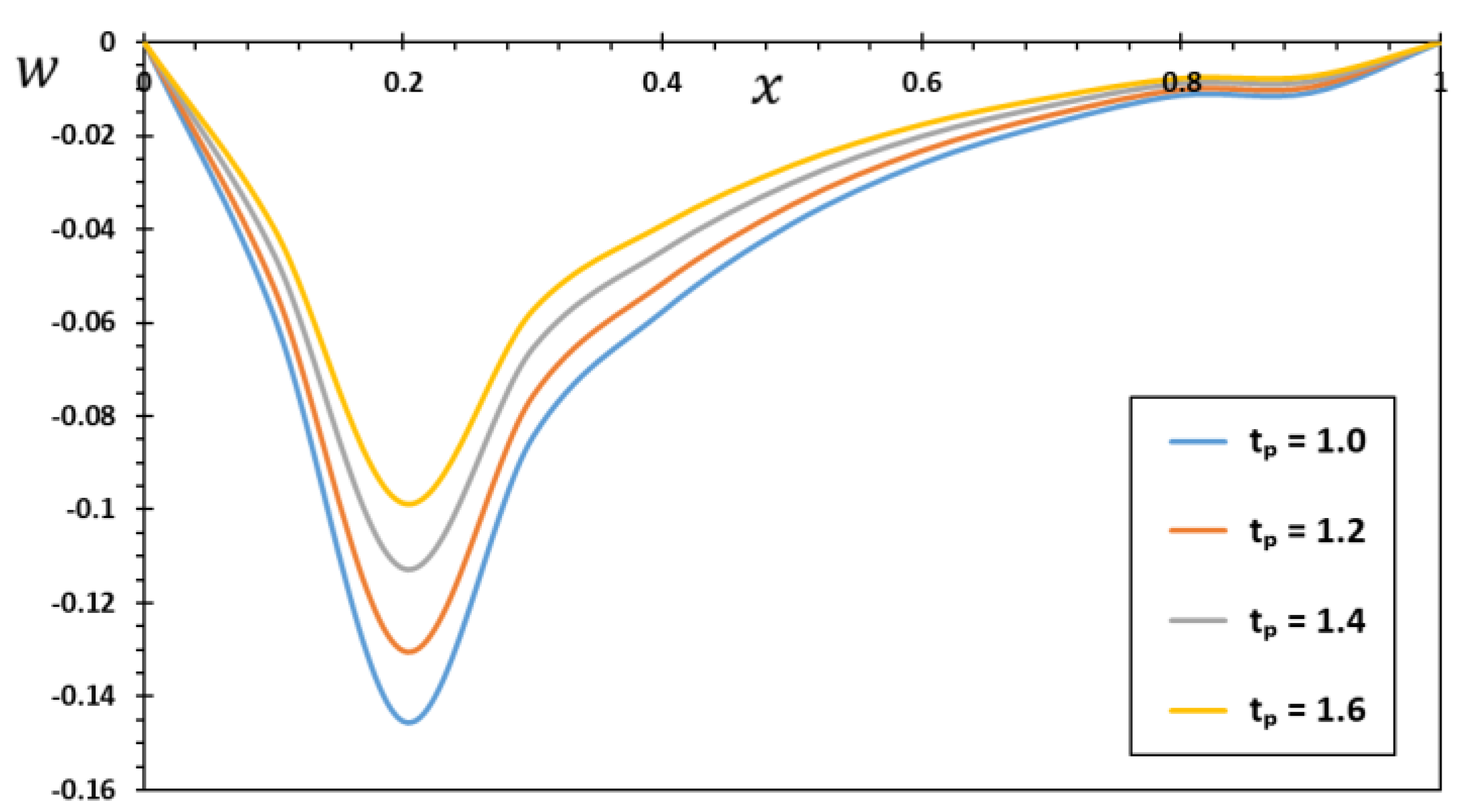
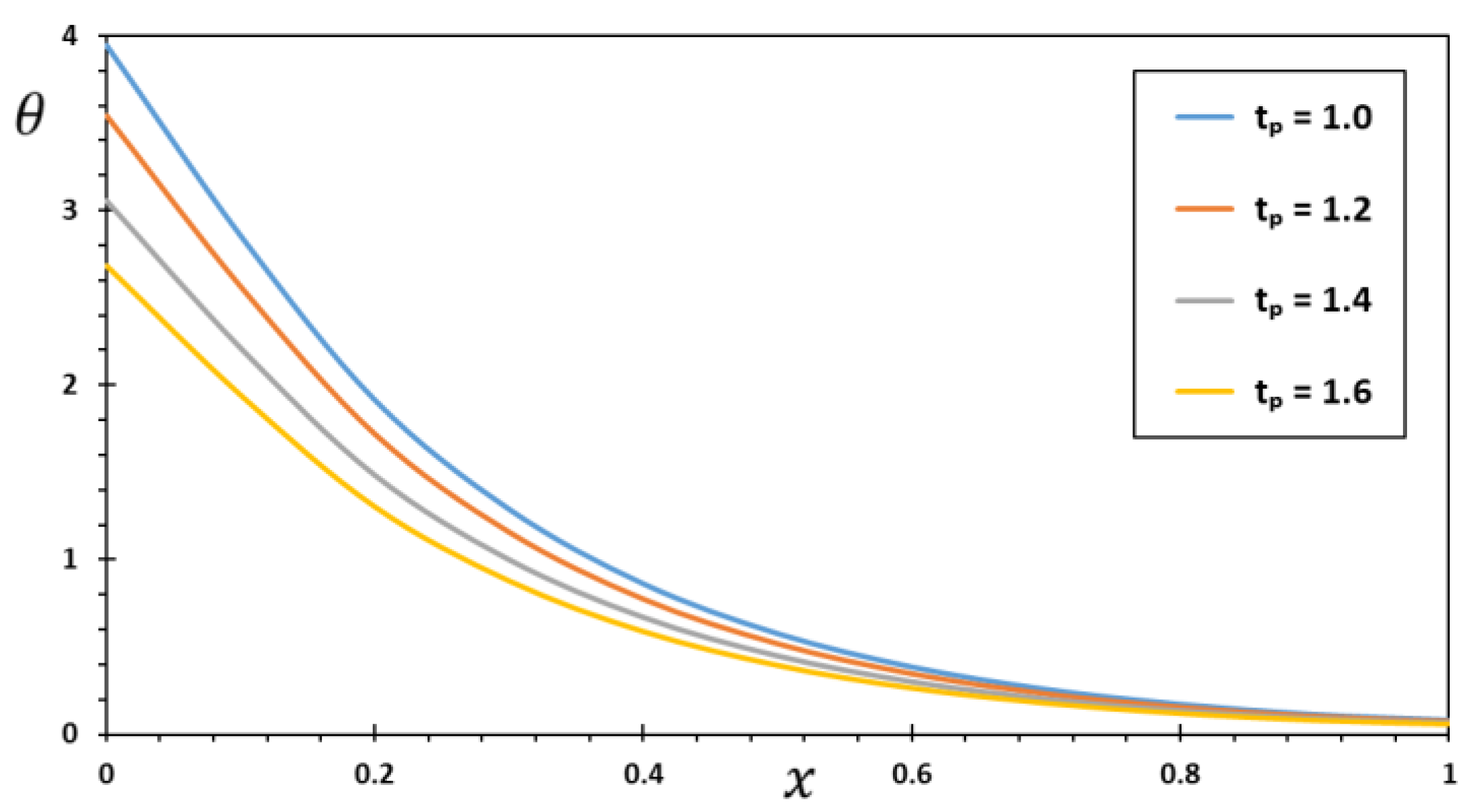
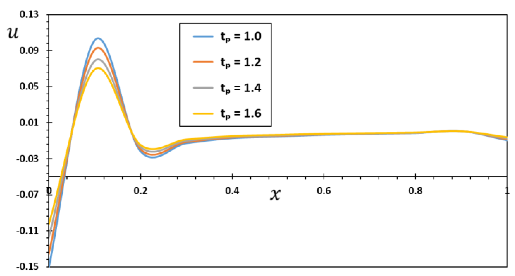
Figure 2,
Figure 3,
Figure 4 and
Figure 5 show the numerical values of the different fields for the purpose of investigating how the laser pulse length
affects the relationship between the dimensionless temperature and the amount of deflection and deformation that occurs inside the microbeam. All other influencing factors involving
,
,
,
, and
remain constant in the numerical calculations.
When the solid microbeam is exposed to pulsed laser light on its surface, the material inside begins to vibrate in the form of waves. As shown in
Figure 2 and
Figure 4, thermoelastic waves are formed by thermal expansion near the surface during pulsed laser heating and are transmitted to the microbeam, which leads to increased deformation and deflection.
Due to the short length of the laser pulse, the heating process will be extremely fast, making the Fourier transfer theory invalid, as it predicts infinite velocities for heat waves. For this reason, a modified non-Fourier heat transfer equation (MGT model) was used in the present work, considering that thermal signals can only travel at a finite speed within the medium. These results demonstrate that the MGTE model shows excellent practical and theoretical consistency for mechanical properties.
Increases in the laser pulse length increase the temperature and the intermolecular distances between the beam materials, while simultaneously reducing the intermolecular thrust. As the duration of the laser pulse increases, the temperature decreases within the microbeam, which stands on the viscoelastic Pasternak foundation (see
Figure 3). This is because the structural pieces are moved at such a high rate by an ultrashort laser pulse that the resulting inertial forces are so great that the structure vibrates more than usual. One thing to keep in mind is that in the laser process, thermoelasticity and momentum coexist and can have an effect on each other, although these two phenomena are rarely studied together.
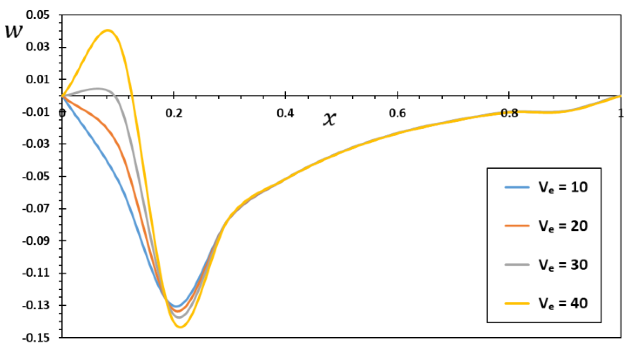
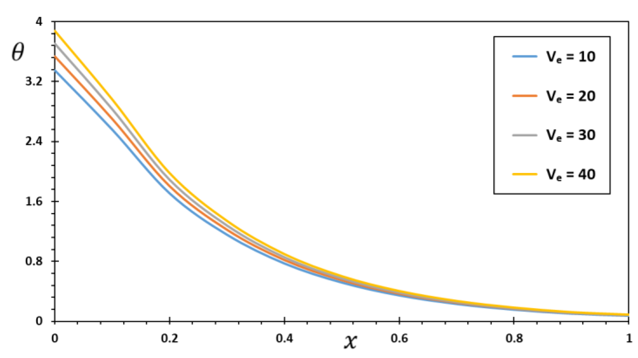
8.3. The Effect of Electrothermal Voltage
The thermoelectric microbeam that is the subject of this investigation is given a thermal load through electrothermal operation by having an external circuit added to the first edge of the beam. In the micro-structures and machinery industry, thermoelectric activation is often used to excite and tune harmonic resonators. Thermally tuned micro/nanoelectromechanical and electromechanical devices are useful for many applications, such as communication systems, process filtration, systems with gyroscopes, power control, and sensitivity detection. The fluctuations of beam deflection and other investigated thermomechanical fields are expressed in
Figure 7,
Figure 8,
Figure 9,
Figure 10 and
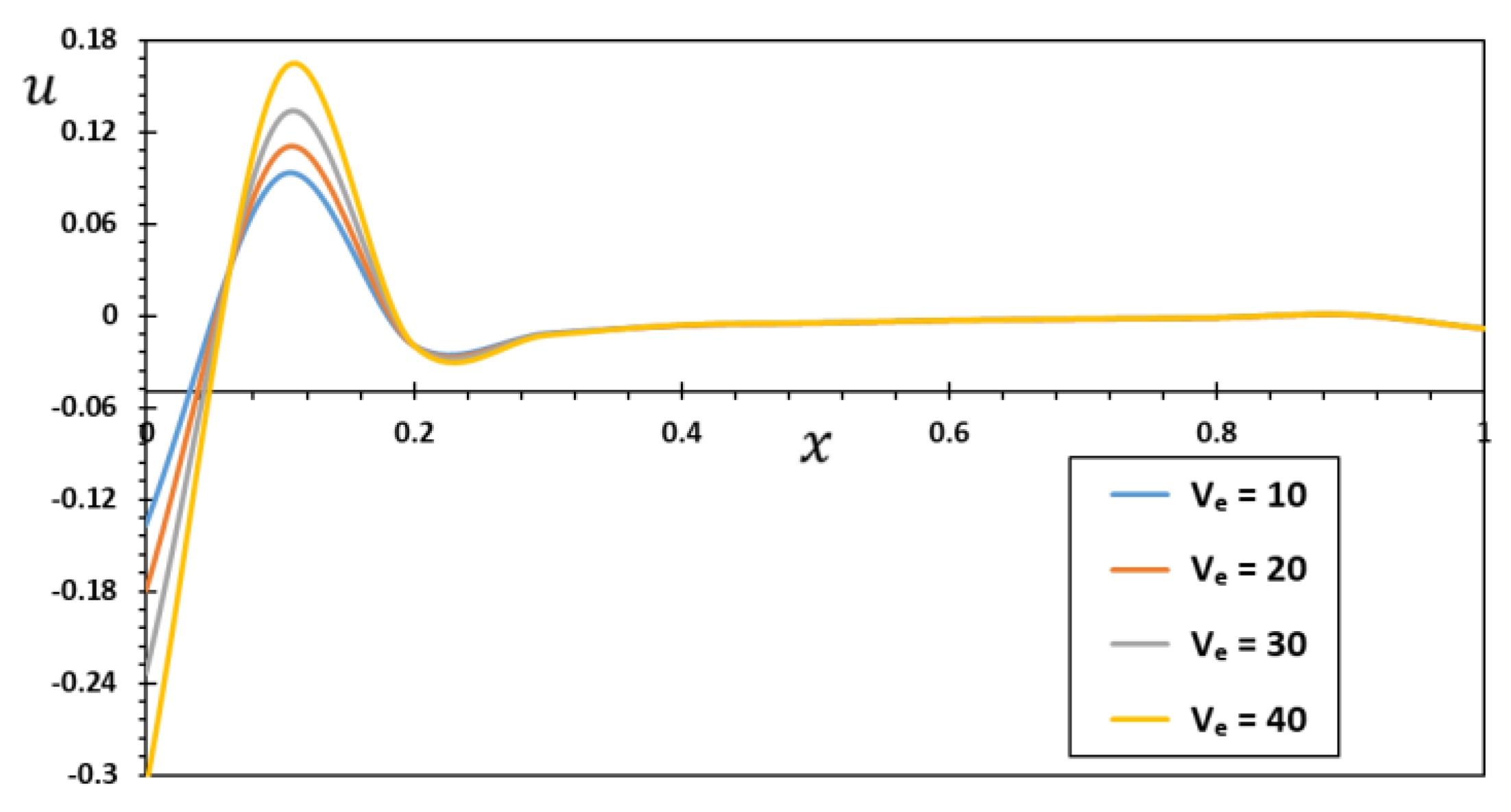
Figure 11 as a response to the applied thermoelectric load (voltages
). In this case, the microspheres would be electrically excited by applying different values of the thermoelectric voltages,
V,
V,
V, and
V. At the same time, the other influencing constants will be assumed to be constant.
From
Figure 7, it is interesting to note that the amount of deflection increases with increasing electrical voltages. This is due to the increase in the thermal and electrical load (electrothermal voltage) produced inside the microbeam. It is well known that its temperature increases as current travels through a conductor. Collisions between moving electrons and the conductor’s atoms cause the electrons to lose some of their energy, which is then transformed into heat when the electrons pass through the conductor. As a result, the conductor’s temperature rises.
Figure 8 shows the significant effect of voltage on the temperature distribution. With the increase in the amount of voltage in the electrical circuit from the first end of the microbeam, the thermal load increases, leading to an increase in temperature. Temperature differences decrease as one moves away from the source of the electric heat flow.
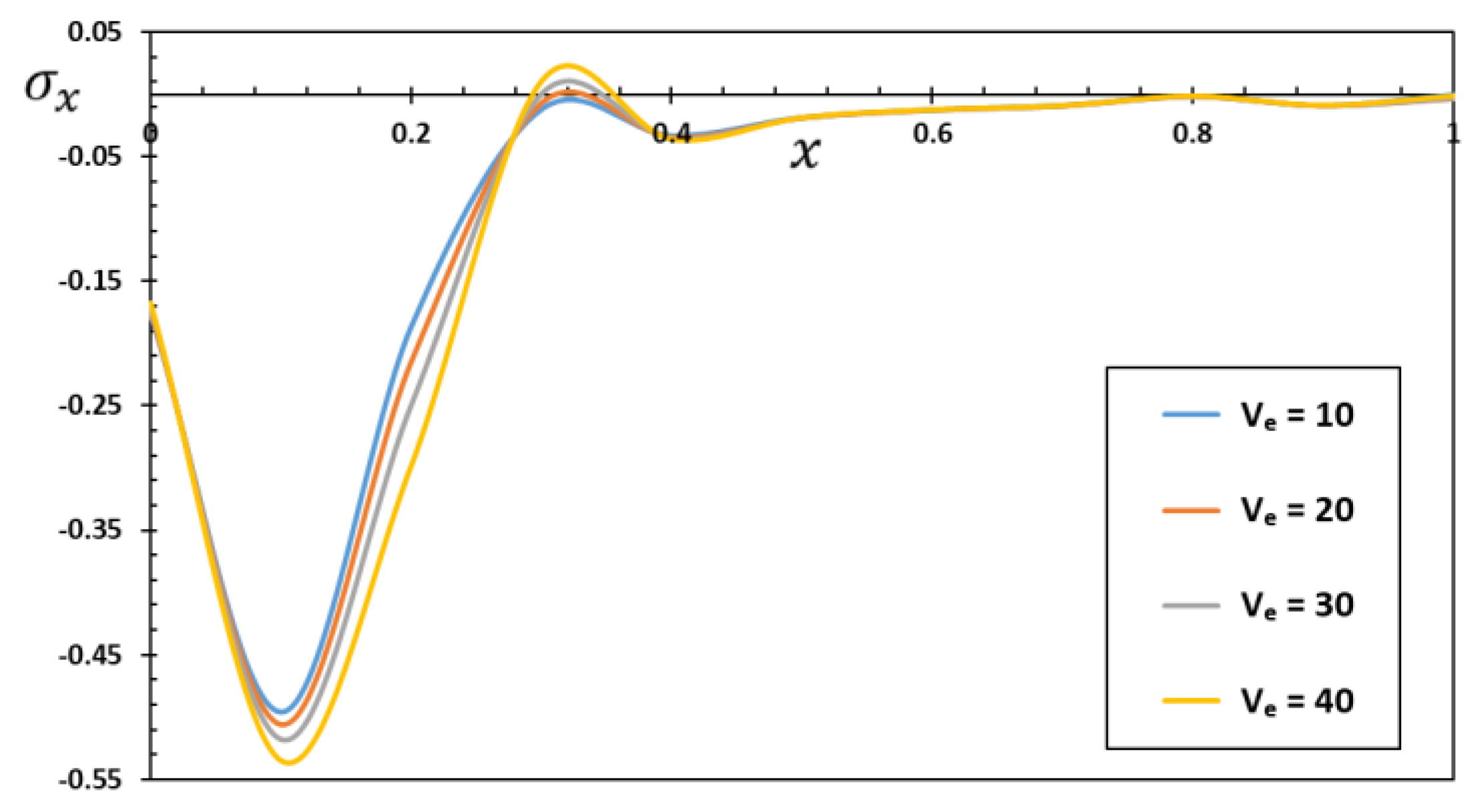
Figure 9 shows that the compressive stress inside the microbeams increases when the ferroelectric voltage rises. This causes the microbeams to buckle and the bending moment to increase. From
Figure 9, it can be expected that the shape of the microbeams will change near the thermoelectric load at the beginning of the microbeam. This is because the microbeam is subjected to a compressive force that increases as the thermoelectric potential increases.


