Article

Evaluation of Photocatalytic Activity and Electrochemical Properties of Hematite Nanoparticles

1
Nanotechnology & Catalysis Research Centre, University of Malaya, Kuala Lumpur 50603, Malaysia
2
Department of Chemistry, Faculty of Mathematics and Natural Sciences, Universitas Islam Indonesia, Kampus Terpadu UII, Jl. Kaliurang Km 14, Sleman, Yogyakarta 55584, Indonesia
3
Environmental and Climate Technology, Korea Institute of Energy Technology (KENTECH), 200 Hyeoksin-ro, Naju 58330, Republic of Korea
4
Department of Physics, Sathyabama Institute of Science and Technology, Chennai 600119, India
5
Department of Chemistry, College of Natural and Computational Sciences, Debre Berhan University, Debre Berhan P.O. Box 445, Ethiopia
6
Laboratoire TIMR UTC-ESCOM, Centre de Recherche de Royallieu, Rue du Docteur Schweitzer, CEDEX CS 60319, F-60203 Compiègne, France
7
Faculty of Chemical Engineering, Ho Chi Minh City University of Technology (HCMUT), Ho Chi Minh City 700000, Vietnam
8
Department of Electrical and Mechanical Engineering, Nagoya Institute of Technology, Gokiso-cho, Showa-ku, Nagoya 466-8555, Japan
*
Authors to whom correspondence should be addressed.
Symmetry 2023, 15(6), 1139; https://doi.org/10.3390/sym15061139
Submission received: 23 April 2023 / Revised: 10 May 2023 / Accepted: 22 May 2023 / Published: 24 May 2023

Abstract

:
The symmetric nano morphologies, asymmetric electronic structures, and as well as the heterojunctions of the developed photocatalytic systems perform a vital role in promoting light absorption, separation of electron and hole pairs and charge carrier transport to the surface when exposed to near-infrared (NIR) light. In this present work, we synthesized hematite (α-Fe2O3) nanoparticles (NPs) by a facile hydrothermal method and studied their structural, optical, and photocatalytic properties. Powder X-ray diffraction (XRD) confirmed the rhombohedral phase of the α-Fe2O3 NPs, and Fourier transform infrared spectroscopy (FT-IR) was used to investigate symmetric and asymmetric stretching vibrations of the functional groups on the surface of the catalysts. The optical bandgap energy was estimated to be 2.25 eV using UV-Vis diffuse reflectance spectroscopy (UV-Vis DRS) and scanning electron microscopy (SEM) images indicated sphere like morphology. The oxidation and reduction properties of α-Fe2O3 NPs were analyzed by cyclic voltammetry (CV). The α-Fe2O3 NPs were utilized for the degradation of methylene blue (MB) dye under natural sunlight. The experimental results demonstrate that the degradation efficiency was achieved at 33% in 2 h, and the pseudo-first-order rate constant was calculated to be 0.0033 min−1.

1. Introduction

Advances in the field of nanotechnology over the past few decades have enabled researchers to develop and synthesize nanomaterials with unique physicochemical properties for photocatalytic applications. Among these nanomaterials, metal-oxide-based nanoparticles have attracted great attention due to their excellent physiochemical properties, which are largely different from their bulk counterpart. Nanomaterials have become a fascinating class of materials that are highly sought after for various useful applications. Incorporating nanoscale materials into catalyst research generates new ideas for the development of catalyst science. Nanocatalysts have high activity and selectivity, allowing them to improve the rate and yield of catalytic reactions. The photodegradation of organic pollutants is significantly increased when metal oxide nanoparticles are used as catalysts. Additionally, the catalytic performance of metal oxides depends not only on their composition but also on their structure, phase, shape, size, particle size, and the particle agglomeration of the dispersed sample. Advancement in industrialization, leading to toxic by-products, has altered the environment by unleashing a distinct variety of toxins and emissions of hazardous gases into the atmosphere [1,2,3]. Therefore, conventionally implemented strategies such as immobilization, biological and chemical oxidation, and incineration have been largely employed to treat several types of organic and toxic industrial contaminants [4,5]. Nanomaterials (NMs), due to their nanoscale sizes, have augmented a new prospect for their several industrial and environmental applications, including sewage treatment and removal of hazardous contaminants [6,7,8]. Confronting the subject of treatment of hazardous contaminants from the environment, NMs delivering unique optical, magnetic, or electrical properties become a fundamental key for environmental remediation [9]. Therefore, the distinct physicochemical material characteristics that were unattainable in the conventional bulk matrix drew several research scholars and scientists to elevate their attention to the field of nanoscience and technology [10,11,12]. Metal oxide nanoparticles such as TiO2, ZnO, SnO2, and ZrO2 and their combination with other metals/metal oxides are effective photocatalysts in water treatment processes, including pharmaceutical and dye-containing effluents [10,11,12,13,14,15,16,17]. Among all metal oxide NPs, iron oxide nanoparticles (Fe2O3 NPs) have received much attention for organic pollutants degradation and biomedical applications, etc., due to their low cost, low toxicity, and unique magnetic properties [18,19]. Iron oxide can exist in different polymorphs, including magnetite (Fe3O4), wustite (FeO), maghemite (γ-Fe2O3), and hematite (α-Fe2O3), of which hematite is thermodynamically stable phase under ambient conditions [20,21,22]. Synthesis of α-Fe2O3 NPs was reported by using various methods [23,24,25,26,27,28]. Hematite (α-Fe2O3) is a metal-oxide-based semiconductor which has been widely investigated in the field of photocatalysis, including photocatalytic water splitting, CO2 reduction, and organic pollutants degradation. It has a narrow bandgap energy of 2.1 eV, which allows light absorption in the visible region up to 570 nm, as well as suitable VB and CB edge position for water splitting, CO2 reduction, and dye degradation. In addition, it exhibits several favorable properties, including earth abundance, nontoxicity, facile synthetic accessibility, and high physicochemical stability [29]. Therefore, in the present work, α-Fe2O3 nanoparticles were synthesized by hydrothermal route, and their photocatalytic and electrochemical activities were studied.

2. Experimental Procedure

2.1. Materials

For the hydrothermal synthesis of α-Fe2O3 NPs, the following chemicals were used without any further purification. Analytical-grade ferric nitrate nonahydrate (Fe(NO3)3·9H2O), ammonia (NH3) solution, and absolute ethanol were purchased from Sigma-Aldrich.

2.2. Synthesis of α-Fe2O3 Nanoparticles

For the hydrothermal synthesis of α-Fe2O3 NPs [20], an iron source, Fe (NO3)3·9H2O (1.8 g), was dissolved in 20 mL of distilled water to form a homogeneous solution. Subsequently, an ammonia solution was added dropwise to the above reaction solution under constant stirring for 30 min to adjust the pH value to 9.0. Subsequently, the reaction mixture was transferred to a 25 mL Teflon-lined stainless-steel autoclave. The autoclave was then heated at 150 °C for 10 h in a heating oven and naturally cooled to room temperature. Finally, the resulting product was washed several times with distilled water followed by ethanol and dried at 80 °C in a drying oven.

2.3. Study of Photocatalytic Activity

The photocatalytic degradation performance of α-Fe2O3 NPs was evaluated using MB dye as a model pollutant. In a typical photocatalytic degradation reaction, 40 mg of the catalyst powder was dispersed in 60 mL of a solution containing 10 ppm MB dye and stirred for 30 min. Before starting the photocatalytic reaction, the reactor was kept in the dark and stirred for 30 min to ensure the adsorption/desorption equilibrium. During this time, MB dye molecules were adsorbed on the surface of the α-Fe2O3 NPs. Subsequently, the reactor was exposed to natural outdoor sunlight, and 5 mL aliquots were taken from the reaction mixture every 30 min interval. The reaction mixture was then centrifuged, and the absorbance of the supernatant was measured by UV–Vis spectroscopy at the maximum absorption wavelength of the MB dye (λmax = 662 nm). The percentage of degradation efficiency was estimated by Equation (1)
Degradation   ( % ) = C 0 C C 0 × 100
where C0 and C denote the absorbance initially before exposure to sunlight and after exposure time t, respectively.

2.4. Study of Electrochemical Activity

The electrochemical activity of α-Fe2O3 NPs was evaluated using a three-electrode system. A α-Fe2O3 drop-casted GEC acted as the working electrode, Pt wire as the counter electrode, and Ag/AgCl as the reference electrode. A 0.5 M Na2SO4 solution was used as an electrolyte for electrochemical activity studies. The potential was applied to the working electrode with respect to the Ag/AgCl reference electrode in the range of −2.0 to 2.0 at a scan rate of 20 mV/s. The working electrode was fabricated as follows: First, the GCE surface was polished using 0.5 µm alumina slurry, followed by rinsing with deionized water and drying at room temperature. Then, 20 mg of the catalyst powder was dispersed in a mixture of ethanol (0.5 mL) and Nafion (5 wt%) solution, followed by sonication for 30 min. This is known as ink or slurry solution. Then, 15 µL of the ink solution was drop-casted onto the surface of the GEC and allowed to dry at room temperature. Electrochemical impedance measurements were performed using a Versa STST MC impedance spectrometer in the frequency range of 1 Hz to 1 MHz.

2.5. Characterization

The structural properties of the prepared sample were investigated by X-ray diffraction analysis using the Rigaku Multiflex diffractometer (Japan). The surface morphology and chemical composition of the samples were examined by SEM using the EI-Quanta FEG 200F instrument (Thermo Fisher Scientific, USA), which was connected to an EDX detector. The chemical structure and surface functional groups were identified using the FT-IR instrument (Perkin Elmer, USA). The optical characteristic of the sample was explored using the Cary 50 UV–Vis spectrophotometer (Varian Technologies, USA).

3. Results and Discussion

3.1. Structural Analysis

XRD analysis was carried out for α-Fe2O3 NPs in the 2θ range of 20–80°, as shown in Figure 1. XRD results reveal that the prepared α-Fe2O3 NPs have a rhombohedral structure with a space group of R-3c, and the diffraction characteristic peaks are indexed as (012), (104), (110), (113), (024), (116), (018), (214), (300), (1010), and (220) planes corresponding to α-Fe2O3. The data were well corroborated with the literature data JCPDS card No. 84-0311 [30]. Furthermore, the appearance of sharp, narrow, and highly intense peaks in the spectrum indicates the crystalline nature and purity of the synthesized α-Fe2O3 sample. The average crystallite size calculated from the three most intense peaks using the Scherrer formula, Equation (2). The average crystal size was found to be 26.2 nm.
D = κ λ β cos θ
where κ denotes the shape factor, which is taken as 0.9, D refers to the average crystallite size, λ is the wavelength of the CuKα X-ray radiation = 0.15406 nm, and β and θ refer to the full width at half maximum intensity of the peaks and the Bragg angle, both measured in radians, respectively. The average crystal size was calculated from the Williamson–Hall (W-H) plot, as shown in Figure 1b. The W-H equation is given in Equation (3).
β cos θ = 0.9 λ D + 4 ε sin θ
The average crystalline size was calculated to be 26.18 nm of the α-Fe2O3 NPs. The crystallite sizes calculated from the Scherrer formula and W-H plot were approximately the similar for the α-Fe2O3 NPs. Furthermore, Figure 1c,d shows the ball-and-stick model and polyhedral model of the rhombohedral crystal structure of α-Fe2O3, respectively, where the arrangement of Fe3+ and O2− ions in α-Fe2O3 can be seen. Moreover, corundum structured and crystallized in the trigonal R-3c space group. Fe3+ was bonded to six equivalent O2− atoms to form a distorted face, edge, and corner-sharing FeO6 octahedron mixture. The angles of the corner-sharing octahedral tilt range from 48–60°. Three Fe-O bond lengths were shorter (1.98 Å) and three were longer (2.13 Å). O2− was bonded to four equivalent Fe3+ atoms to form a trigonal pyramid with distorted edges and corner-sharing OFe4 [19].

3.2. FT-IR Analysis

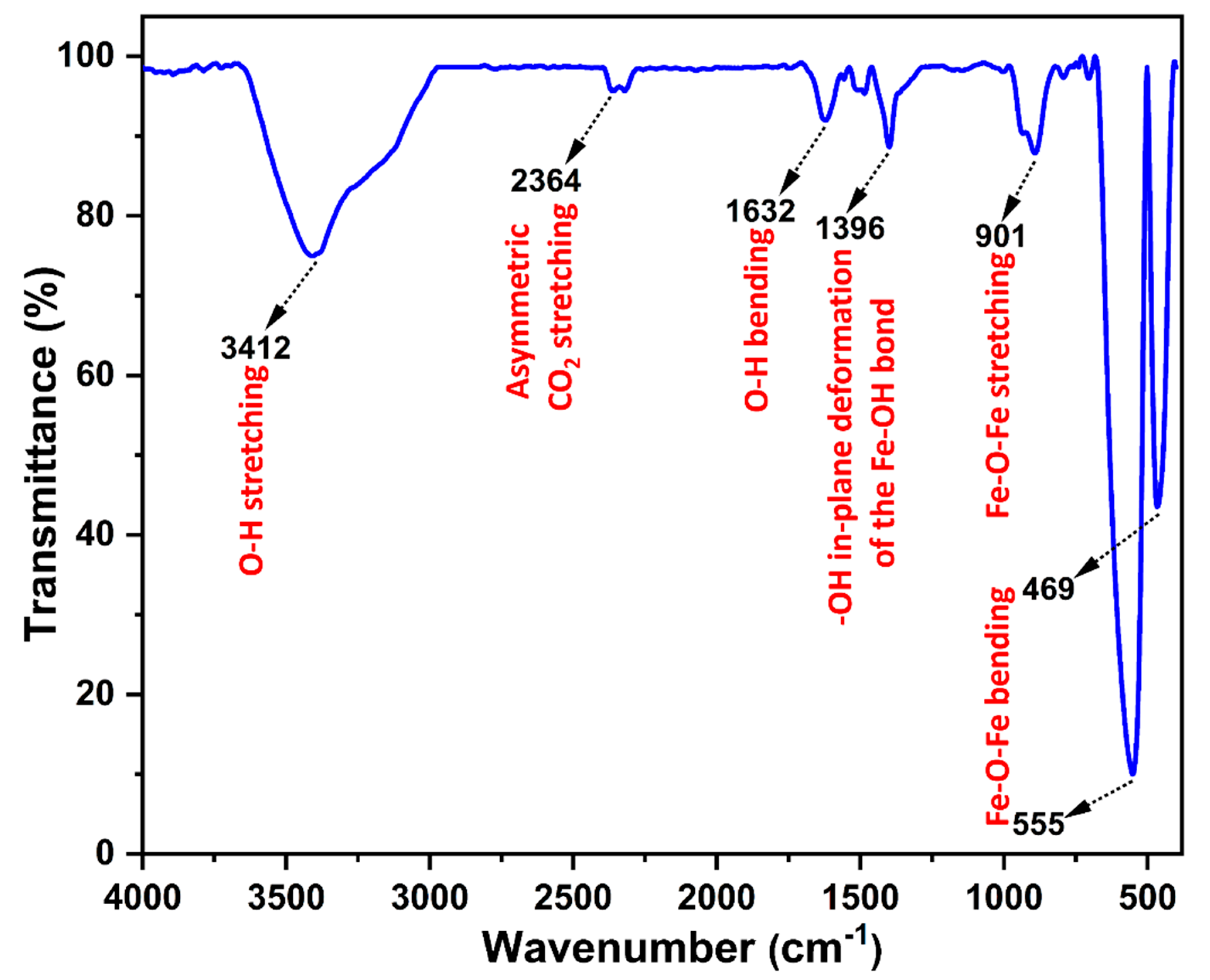
FT-IR analysis was used to understand the chemical structure of the sample as shown in Figure 2. The weak peak that appeared at 2364 cm−1 can be attributed to the CO2 asymmetric stretching vibration present in the atmosphere. The band at 1396 cm−1 can be attributed to the -OH in-plane deformation of the Fe-OH bond. The band at 901 cm−1 corresponds to the stretching vibration of the Fe-O-Fe bond [31,32]. The bands at 555 and 469 cm−1 can be assigned to the Fe-O-Fe bending vibration of α-Fe2O3 NPs [33].

3.3. Morphology

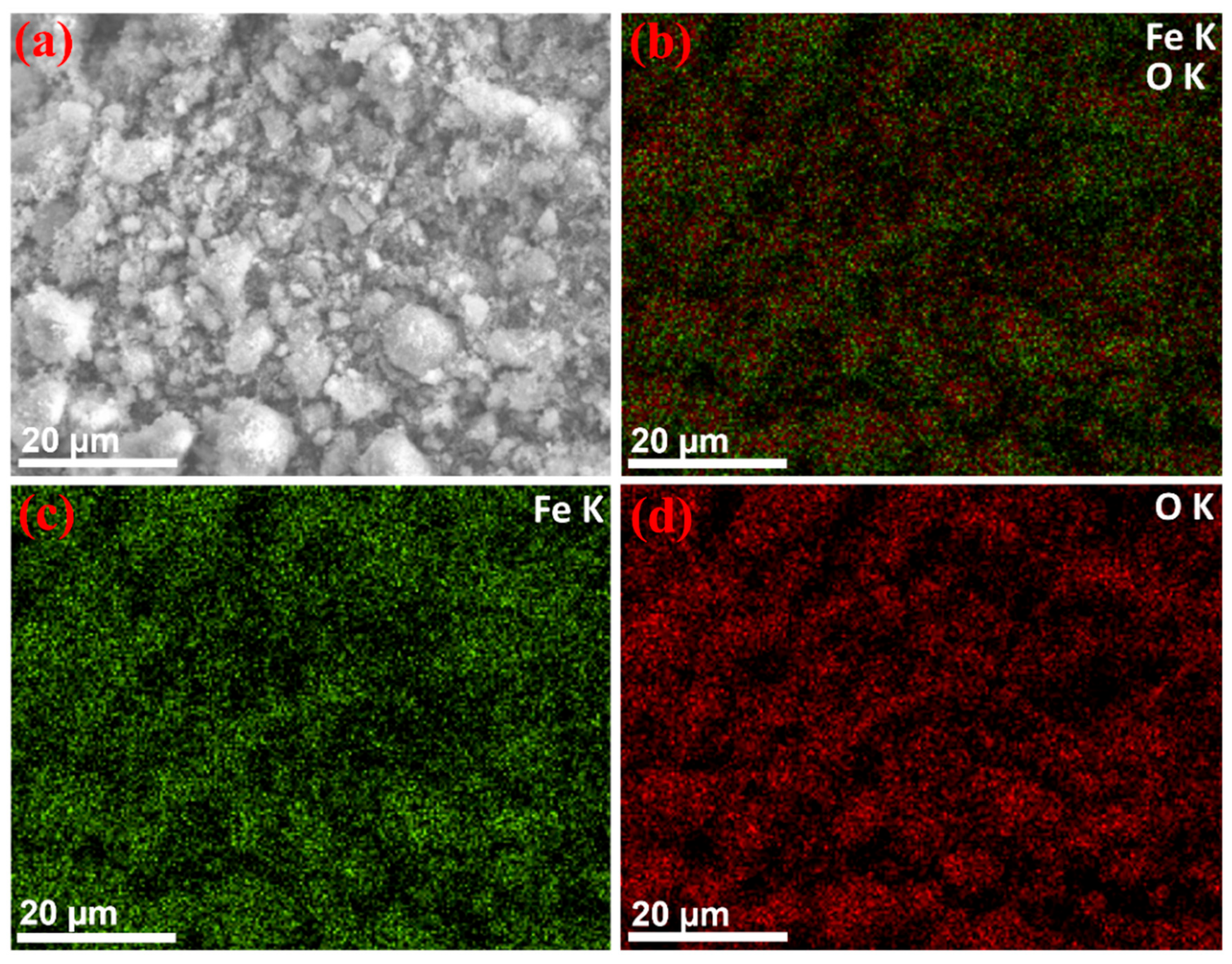
SEM and EDX were performed to evaluate the morphology and chemical composition of the α-Fe2O3 NPs. Figure 3a–c shows the SEM micrographs of the α-Fe2O3 NPs. Figure 3a shows the presence of fine grains (b and c) with a spherical shape, with some agglomeration. The average particle size (diameter) was found to be around 150 nm, using ImageJ software (Figure 3d). Figure 3e shows the EDX spectrum of α-Fe2O3 NPs, which detected the peaks of Fe and O, resulting in α-Fe2O3 NPs with high purity. The EDS images of the α-Fe2O3 NPs are shown in Figure 4. The figure shows that Fe and O are evenly distributed, confirming the homogeneity of the sample. Additional peaks for Cl were found in the EDX spectra due to the presence of impurities in the Fe (NO3)3·9H2O starting material. Furthermore, the Fe:O atomic ratio of α-Fe2O3 NPs, obtained from the SEM-EDS analysis, is estimated to be approximately 2:3, which is very closely consistent with the theoretical weight ratio (2:3) of Fe2O3.

3.4. Dynamic Light Scattering (DLS)

The hydrodynamic particle size distribution of the α-Fe2O3 NPs was estimated using dynamic light scattering (DLS). Figure 5 shows the DLS size distribution plot of the α-Fe2O3 NPs dispersed in DW. According to the histogram, the average hydrodynamic particle size was found to be 141 nm.

3.5. Optical Properties

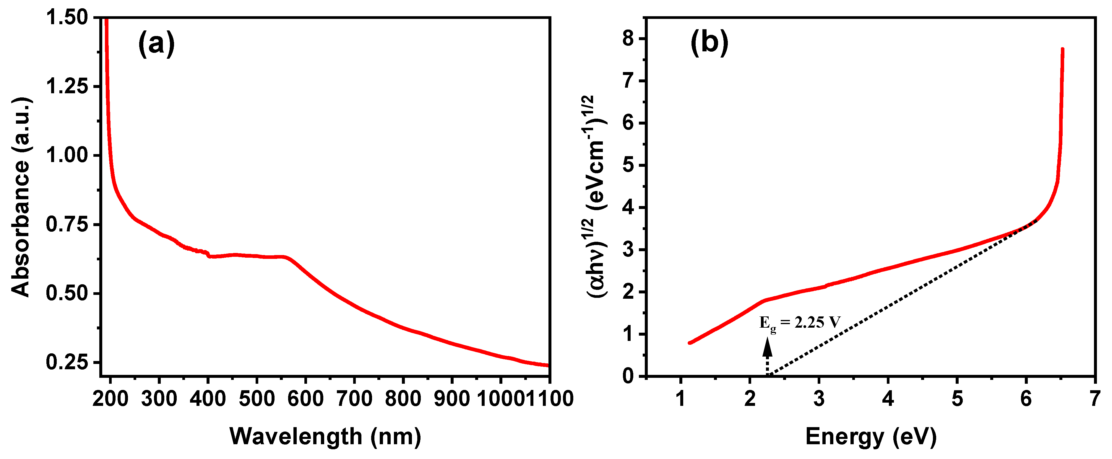
UV–Vis spectroscopy was performed to evaluate the absorbance and bandgap of the α-Fe2O3 NPs, as shown in Figure 6a,b. The maximum absorption was observed at 560 nm. Based on these results, α-Fe2O3 NPs can be used in photocatalytic MB dye degradation that requires visible-light absorption. The band gap energy was calculated by extrapolating the line from the from α h ν 1 / 2 versus h ν , as shown in Figure 6b. The band gap was calculated to be 2.25 eV, which is in good agreement with an earlier report [34].

3.6. Electrochemical Property Study

The cyclic voltammetry curve of the α-Fe2O3 NPs is shown in Figure 7. The observed anodic and cathodic peaks represent the oxidation and reduction reactions associated with the interconversion of Fe0 and Fe3+ species in the solution, respectively. The presence of double anodic peaks at −0.39 V and 0.32 V might be due to the oxidation of Fe0 to Fe2+ and then to Fe2+ to Fe3+ at the applied potential range and pH of the solution. However, the cathodic peak corresponding to the conversion of Fe3+ to Fe2+ for the reverse reduction reaction almost gets diminished due to the irreversible reaction with the formation of a solid electrolyte interface layer [35]. The Nyquist plot of the electrochemical impedance spectra (EIS) of the synthesized α-Fe2O3 NPs is shown in Figure 7b. The Nyquist plot was drawn by imaginary (Z″) versus real (Z′) impedance. The Figure 7b inset shows the equivalent circuit diagram. This study shows the kinetics of the charge transfer between the active electrode and the electrolyte interface. The presence of the semicircle with a small diameter in the higher frequency region indicates the redox reaction, and a linear slope in the lower frequency region in the plot indicates the diffusion-controlled process at the electrode–electrolyte interface. Since the semicircle is quite small, the reaction is kinetically facile, and the ionic conduction and electrolyte diffusion over the porous structure of the electrode is also clearly evident.

3.7. Photocatalytic Activity Study

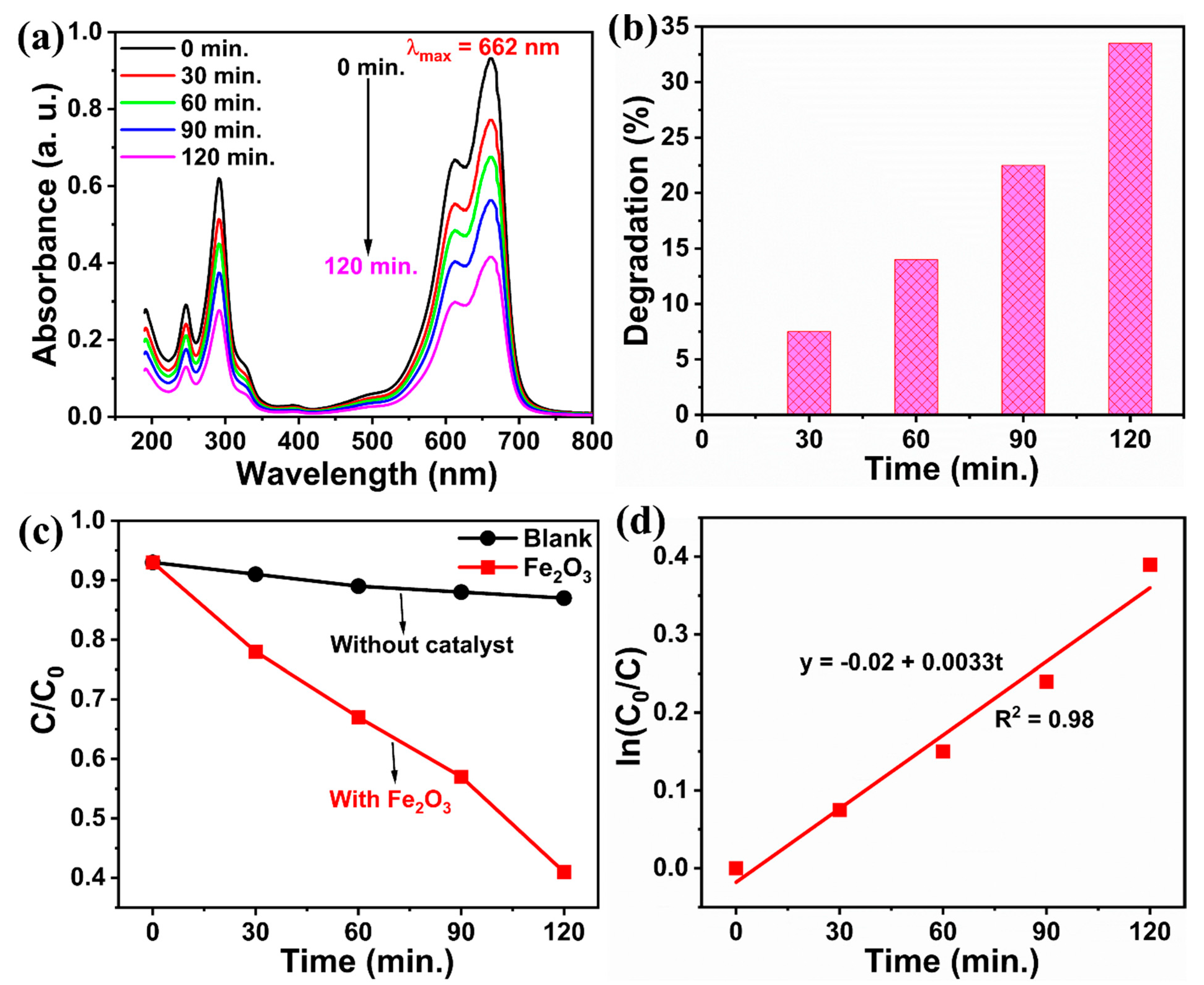
The photocatalytic activity of the α-Fe2O3 NPs for the degradation of the methylene blue dye under sunlight irradiation was evaluated. The degradation of the MB dye irradiated by natural sunlight was observed every 30 min. The intensity of the peak at 662 nm decreased in the presence of the catalyst, complete degradation was observed at 120 min, and the photocatalytic activity is shown in Figure 8a. The photodegradation efficiency of the α-Fe2O3 NPs, as shown in Figure 8b, indicates that 33% of the dye decomposed after 2 h of irradiation. The rate of degradation of MB dye without the catalyst (blank test) and with catalyst is shown in Figure 8c; the photodegradation reaction data can be described well by pseudo-first-order reaction kinetics, given by Equation (4), as shown in Figure 8d.
ln C 0 C = κ 1 t
where k1 is the pseudo-first-order reaction rate constant, and C0 and C are as defined previously in Equation (1). The value of k1 obtained is 0.0033 min−1, and the half-life of the reaction, calculated using t1/2 = 0.693/k1, is 120 min. Table 1 provides a comparison of the photodegradation performances of α-Fe2O3 NPs using different methods for various pollutants under different conditions.
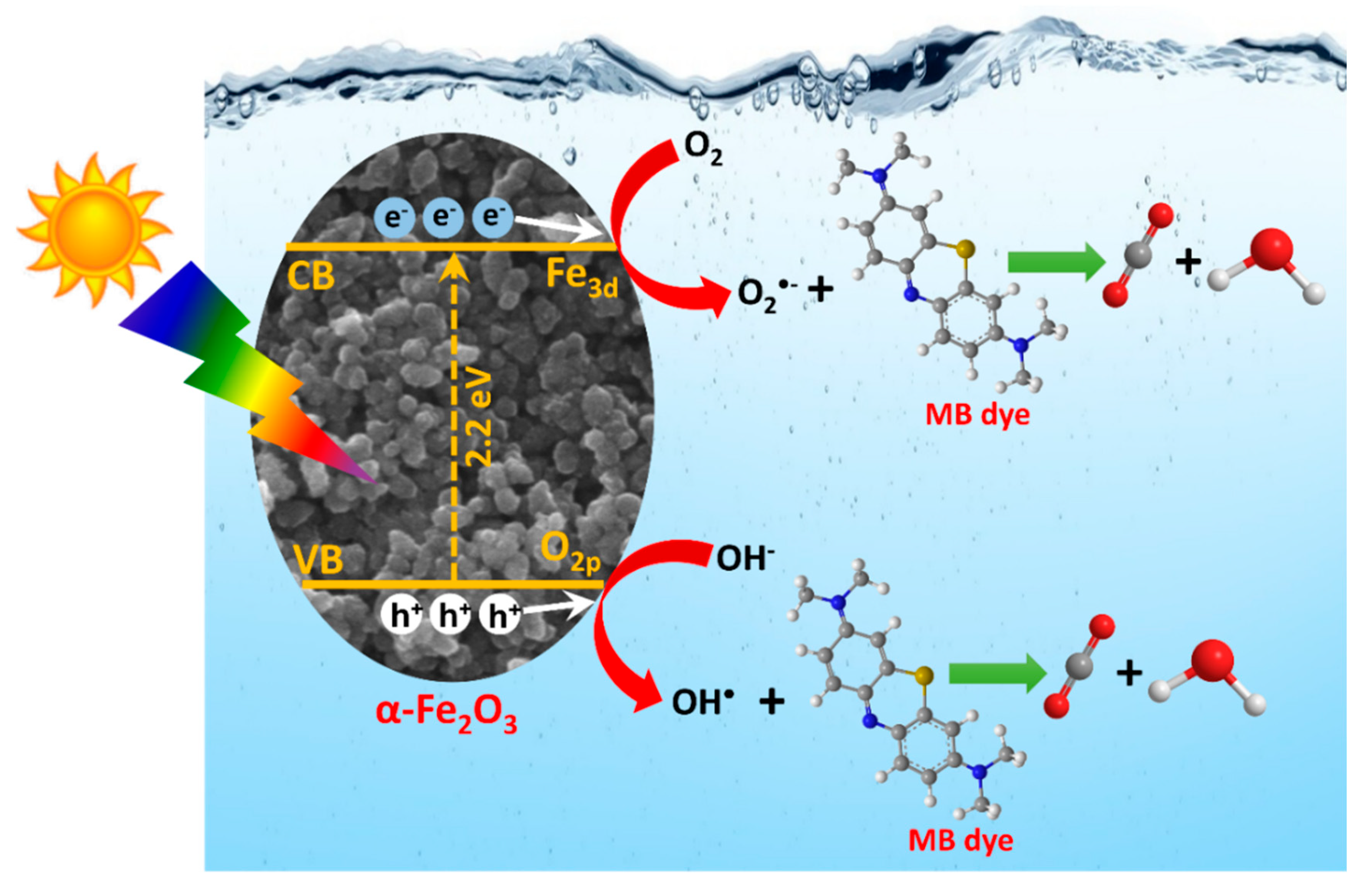
When α-Fe2O3 absorbs sunlight equal to or greater than the bandgap energy, electrons in the valence band are excited to the conduction band, resulting in the generation of holes in the valence band and electrons in the conduction band. Oxygen and water molecules were adsorbed onto the surface of the α-Fe2O3 catalyst. Positive holes in the valence band oxidize OH- or water at the catalyst surface to produce OH radicals, which are extremely strong oxidants (the oxidation potential of the OH radical is 2.80 V). The hydroxyl radicals subsequently oxidize the MB dye and produce CO2 and H2O (Figure 9) [36,37,38]. The electrons on the catalyst surface are rapidly captured by molecular oxygen adsorbed on the catalyst surface and are reduced to form superoxide radical anions (O2•−; the oxidation potential of the superoxide radical anion is −2.4 V). Superoxide radicals react with the MB dye to produce CO2 and H2O, as shown in Equations (5)–(8), respectively.
Fe 2 O 3 + h ν Fe 2 O 3 ( e C B + h V B + )
O 2 + e C B O 2 .
H 2 O + h V B + H + + H O .
M B + O 2 .   and   HO . decompositon   products
Table 1. Comparison of the photocatalytic degradation of various dyes using various α-Fe2O3 nanostructures.
S.No.Catalyst/
Morphology
Contaminant (s)Lamp Power and IrradianceLight% RemovalPseudo-First-Order Rate ConstantReferences
1Porous Fe2O3 nanorodsRhodamine B (RhB)
eosin B,
Methylene blue (MB),
p-nitrophenol,
Methylene orange (MO)
500 W Xe lampSimulated solar light86%
83%
23%
17%
13%
0.0131 min−1[39]
2α-Fe2O3 nanowiresRhB350 W Xenon lamp420 nm cut-off filter85%-[40]
3Porous Fe2O3 nanotubesRhBXenon lampλ ≥ 420 nm99%0.282 min−1[41]
4Cubic Fe2O3
Disc Fe2O3
RhB12
Philips TL 8w/54-7656 bulb lamps
--0.005 min−1
0.042 min−1
[42]
5Mesoporous spindlelike Fe2O3RhBMercury and tungsten mixed light lamp (OSRAM, 250W, including UV and visible light)UV and visible light95%-[43]
6Ultrathin α-Fe2O3 nanosheetsBisphenol S (BPS) A 300 W xenon lamp (PE300BF) 420 nm cut-off filter90%0.0164 min−1[44]
71D α-Fe2O3 nanobraids
1D α-Fe2O3 nanoporous
Congo red (CR)400 W metal halide lamp λ ≥ 365 nm91%
90%
-[45]
8Porous α-Fe2O3 nanorodsMB250 W halide lamp 420 nm cut-off filter95%1.04 × 10⁻² min−1[46]
9α-Fe2O3 hollow sphereSalicylic acid-UV light--[47]
10α-Fe2O3 hollow spindlesPhenolhigh-pressure Hg lamp (500 W, Nanjing Stonetech)UV irradiation (high-pressure Hg lamp is 365 nm after filtering)10%-[48]
11α-Fe2O3 mesoporousSalicylic acidhigh-pressure Hg lampUV irradiation95%-[49]
12α-Fe2O3 hollow microspheresSalicylic acidhigh-pressure Hg lamp (300 W)UV light58%-[50]
13α-Fe2O3 hollow microspheres assisted solvothermal methodRhB300 W Xe lamp 400 nm cut-off filter98%-[51]
14α-Fe2O3Rose Bengal200 W tungsten lamp-98%1.57 × 10⁻² min−1[52]
15α-Fe2O3H2SXe-lamp light source (Oriel, New-port Stratford, Stratford, CT) of intensity 450 W cut-off filter (>420 nm)--[53]
16α-Fe2O3 dendrites,
αFe2O3 nanospindles,
α-Fe2O3 nanorods,
α-Fe2O3 nanocubes
RhB2 mW UV source (λ = 365 nm)82%
83%
84%
84%
0.322 min−1
0.589 min−1
0.8505 min−1
0.876 min−1
[54]
17α-Fe2O3 nanoparticlesRhB500 W xenon lamp 420 nm cutoff filter52%-[55]
181D α-Fe2O3 microrods
1D α-Fe2O3 nanorods
RhB300 W xenon lamp λ > 420 nm -0.00977 min−1
0.148 min−1
[56]
19α-Fe2O3 oblique
α-Fe2O3 truncated nanocubes
RhB300 W Hg lamp λ = 365 nm 59%-[57]
20α-Fe2O3 microflowers,
α-Fe2O3 nanoparticles
α-Fe2O3 nanospindles
RhB500 W xenon lamp 420 nm cut-off filter 98%
94%
91%
-[58]
21flowerlike α-Fe2O3 nanostructuresRhB250 W high-pressure Hg lampUV irradiation59%-[59]
22α-Fe2O3 hollow core/shell hierarchical nanostructuresPhenolhigh-pressure Hg lampUV irradiation60%-[60]
23α-Fe2O3 nanoparticleMBoutdoor sunlight-33%0.0033 min−1Present work

4. Conclusions

Hematite (α-Fe2O3) NPs were successfully synthesized using a facile hydrothermal method. From powder XRD analysis, the as-synthesized α-Fe2O3 was found to have a rhombohedral phase with high crystallinity. The FT-IR spectrum indicated the presence of a α-Fe2O3 phase in the synthesized sample. The SEM images indicate the formation of an aggregated spherelike morphology. DLS indicated that the synthesized hematite particles dispersed in DW were stable with an average hydrodynamic size of 141 nm. The photocatalytic activity of the as-synthesized α-Fe2O3 NPs was also studied for the model contaminant MB dye under natural sunlight irradiation, and it was found that 33% of the dye could be decomposed after 2 h of radiation exposure at natural pH without introducing oxidants.

Author Contributions

Conceptualization, S.S.; Methodology, S.S., J.A.L. and M.-V.L.; Validation, R.P.S., I.F., G.K.W., E.L., M.-V.L. and T.S.; Formal analysis, S.S., R.P.S., J.A.L., I.F., G.K.W., E.L. and T.S.; Investigation, M.-V.L.; Resources, J.A.L.; Data curation, R.P.S., I.F., G.K.W., E.L. and T.S.; Writing—original draft, S.S. All authors have read and agreed to the published version of the manuscript.

Funding

This research was funded by University of Malaya, grant number MG020-2022.

Data Availability Statement

Not Applicable.

Acknowledgments

The authors are grateful to the University of Malaya for funding this work under grant number MG020-2022.

Conflicts of Interest

The authors declare no conflict of interest.

References

  1. Chakraborty, R.; Karmakar, S.; Ansar, W. Advances and Applications of Bioremediation: Network of Omics, System Biology, Gene Editing and Nanotechnology. In Environmental Informatics: Challenges and Solutions; Springer: Singapore, 2022; pp. 167–199. [Google Scholar]
  2. Fatimah, I.; Purwiandono, G.; Hidayat, H.; Sagadevan, S.; Ghazali, S.A.I.S.M.; Oh, W.-C.; Doong, R.-A. Flower-like SnO2 Nanoparticle Biofabrication Using Pometia pinnata Leaf Extract and Study on Its Photocatalytic and Antibacterial Activities. Nanomaterials 2021, 11, 3012. [Google Scholar] [CrossRef] [PubMed]
  3. Das, S.; Gupta, B.; Sarkar, A. Diverse Technological Initiatives for E-Waste Management and Its Impact on Ecosystem. In Conversion of Electronic Waste in to Sustainable Products; Springer Nature: Singapore, 2022; pp. 79–102. [Google Scholar]
  4. Ossai, I.C.; Ahmed, A.; Hassan, A.; Hamid, F.S. Remediation of soil and water contaminated with petroleum hydrocarbon: A review. Environ. Technol. Innov. 2020, 17, 100526. [Google Scholar] [CrossRef]
  5. Eibes, G.; Arca-Ramos, A.; Feijoo, G.; Lema, J.M.; Moreira, M.T. Enzymatic technologies for remediation of hydrophobic organic pollutants in soil. Appl. Microbiol. Biotechnol. 2015, 99, 8815–8829. [Google Scholar] [CrossRef]
  6. Xu, P.; Zeng, G.M.; Huang, D.L.; Feng, C.L.; Hu, S.; Zhao, M.H.; Lai, C.; Wei, Z.; Huang, C.; Xie, G.X.; et al. Use of iron oxide nanomaterials in wastewater treatment: A review. Sci. Total Environ. 2012, 424, 1–10. [Google Scholar] [CrossRef]
  7. Anita Lett, J.; Sagadevan, S.; Weldegebrieal, G.K.; Fatimah, I. Hydrothermal Synthesis and Photocatalytic Activity of NiO Nanoparticles under Visible Light Illumination. Bull. Chem. React. Eng. Catal. 2022, 17, 340–349. [Google Scholar] [CrossRef]
  8. Fatimah, I.; Purwiandono, G.; Jauhari, M.H.; Maharani, A.A.A.P.; Sagadevan, S.; Oh, W.C.; Doong, R.A. Synthesis and control of the morphology of SnO2 nanoparticles via various concentrations of Tinospora cordifolia stem extract and reduction methods. Arab. J. Chem. 2022, 15, 103738. [Google Scholar] [CrossRef]
  9. Fatimah, I.; Purwiandono, G.; Hidayat, A.; Sagadevan, S.; Kamari, A. Mechanistic insight into the adsorption and photocatalytic activity of a magnetically separable γ-Fe2O3/Montmorillonite nanocomposite for rhodamine B removal. Chem. Phys. Lett. 2022, 792, 139410. [Google Scholar] [CrossRef]
  10. Abdullah, N.H.; Shameli, K.; Etesami, M.; Chan Abdullah, E.; Abdullah, L.C. Facile and green preparation of magnetite/zeolite nanocomposites for energy application in a single-step procedure. J. Alloys Compd. 2017, 719, 218–226. [Google Scholar] [CrossRef]
  11. Chenab, K.K.; Sohrabi, B.; Jafari, A.; Ramakrishna, S. Water treatment: Functional nanomaterials and applications from adsorption to photodegradation. Mater. Today Chem. 2020, 16, 100262. [Google Scholar] [CrossRef]
  12. Fatimah, I.; Yahya, A.; Iqbal, R.M.; Tamyiz, M.; Doong, R.-A.; Sagadevan, S.; Oh, W.-C. Enhanced Photocatalytic Activity of Zn-Al Layered Double Hydroxides for Methyl Violet and Peat Water Photooxidation. Nanomaterials 2022, 12, 1650. [Google Scholar] [CrossRef]
  13. Akbari, A.; Sabouri, Z.; Hosseini, H.A.; Hashemzadeh, A.; Khatami, M.; Darroudi, M. Effect of nickel oxide nanoparticles as a photocatalyst in dyes degradation and evaluation of effective parameters in their removal from aqueous environments. Inorg. Chem. Commun. 2020, 115, 107867. [Google Scholar] [CrossRef]
  14. Sharma, N.; Kumar, J.; Thakur, S.; Sharma, S.; Shrivastava, V. Antibacterial study of silver doped zinc oxide nanoparticles against Staphylococcus aureus and Bacillus subtilis. Drug Invent. Today 2013, 5, 50–54. [Google Scholar] [CrossRef]
  15. Hassan, S.M.; Ahmed, A.I.; Mannaa, M.A. Preparation and characterization of SnO2 doped TiO2 nanoparticles: Effect of phase changes on the photocatalytic and catalytic activity. J. Sci. Adv. Mater. Devices 2019, 4, 400–412. [Google Scholar] [CrossRef]
  16. Khezrianjoo, S.; Lee, J.; Kim, K.-H.; Kumar, V. Eco-Toxicological and Kinetic Evaluation of TiO2 and ZnO Nanophotocatalysts in Degradation of Organic Dye. Catalysts 2019, 9, 871. [Google Scholar] [CrossRef]
  17. Sagadevan, S.; Lett, J.A.; Alshahateet, S.F.; Fatimah, I.; Weldegebrieal, G.K.; Le, M.V.; Leonard, E.; Paiman, S.; Soga, T. Photocatalytic degradation of methylene blue dye under direct sunlight irradiation using SnO2 nanoparticles. Inorg. Chem. Commun. 2022, 141, 109547. [Google Scholar] [CrossRef]
  18. Akbarzadeh, A.; Samiei, M.; Davaran, S. Magnetic nanoparticles: Preparation, physical properties, and applications in biomedicine. Nanoscale Res. Lett. 2012, 7, 144. [Google Scholar] [CrossRef]
  19. Wu, W.; Wu, Z.; Yu, T.; Jiang, C.; Kim, W.S. Recent progress on magnetic iron oxide nanoparticles: Synthesis, surface functional strategies and biomedical applications. Sci. Technol. Adv. Mater. 2015, 16, 023501. [Google Scholar] [CrossRef]
  20. Wang, F.; Qin, X.; Meng, Y.; Guo, Z.; Yang, L.; Ming, Y. Hydrothermal synthesis and characterization of α-Fe2O3 nanoparticles. Mater. Sci. Semicond. Process. 2013, 16, 802–806. [Google Scholar] [CrossRef]
  21. Sun, Y.; Zhang, Y.; Tian, Y.; Liu, Y.; Zhao, G.; Li, F.; Fang, D. Facile synthesis of snowflake-like magnetic Fe–Ni alloy with high magnetic properties. Mater. Res. Innov. 2012, 16, 413–416. [Google Scholar] [CrossRef]
  22. Wu, Y.; Wang, X. Preparation and characterization of single-phase α-Fe2O3 nano-powders by Pechini sol–gel method. Mater. Lett. 2011, 65, 2062–2065. [Google Scholar] [CrossRef]
  23. Teja, A.S.; Koh, P.Y. Synthesis, properties, and applications of magnetic iron oxide nanoparticles. Prog. Cryst. Growth. Character. 2009, 55, 22–45. [Google Scholar] [CrossRef]
  24. Yang, X.; Jiang, W.; Liu, L.; Chen, B.; Wu, S.; Sun, D.; Li, F. One step hydrothermal synthesis of highly water soluble secondary structured Fe3O4 nanoparticles. J. Magn. Magn. Mater. 2012, 324, 2249. [Google Scholar] [CrossRef]
  25. Lu, J.; Jiao, X.; Chen, D.; Li, W. Solvothermal synthesis and characterization of Fe3O4 and ɤ-Fe2O3 nanoplates. J. Phys. Chem. C 2009, 113, 4012–4017. [Google Scholar] [CrossRef]
  26. Islam, N.; Phong, L.V.; Jeong, J.R.; Kim, C.G. A facile route to sonochemical synthesis of magnetic iron oxide (Fe3O4) nanoparticles. Thin Solid Film. 2011, 519, 8277–8279. [Google Scholar] [CrossRef]
  27. Reda, S. Synthesis of ZnO and Fe2O3 nanoparticles by sol–gel method and their application in dye-sensitized solar cells. Mater. Sci. Semicond. Process. 2010, 13, 417–425. [Google Scholar] [CrossRef]
  28. Dealership, E.; Bakhtiari, F.; Alizadeh, M.; Ranjbar, M. Direct thermal decomposition synthesis and characterization of hematite (α-Fe2O3) nanoparticles. Mater. Sci. Semicond. Process. 2012, 15, 91–97. [Google Scholar]
  29. Wang, R.; Chen, Y.; Fu, Y.; Zhang, H.; Kisielowski, C. Bicrystalline Hematite Nanowires. J. Phys. Chem. B 2005, 109, 12245–12249. [Google Scholar] [CrossRef]
  30. Li, X.; Wei, W.; Wang, S.; Kuai, L.; Geng, B. Single-crystalline α-Fe2O3 oblique nano parallelepipeds: High-yield synthesis, growth mechanism and structure enhanced gas-sensing properties. Nanoscale 2011, 3, 718–724. [Google Scholar] [CrossRef]
  31. Liu, X.M.; Fu, S.Y.; Xiao, H.M.; Huang, C.J. Preparation and characterization of shuttle-like α-Fe2O3 nanoparticles by supermolecular template. J. Solid State Chem. 2005, 178, 2798–2803. [Google Scholar] [CrossRef]
  32. Du, Y.; Fan, H.; Wang, L.; Wang, J.; Wu, J.; Dai, H. α-Fe2O3 nanowires deposited diatomite: Highly efficient absorbents for the removal of arsenic. J. Mater. Chem. A 2013, 1, 7729–7737. [Google Scholar] [CrossRef]
  33. Tharani, K.; Christy, A.J.; Sagadevan, S.; Nehru, L. Photocatalytic and antibacterial performance of iron oxide nanoparticles formed by the combustion method. Chem. Phys. Lett. 2021, 771, 138524. [Google Scholar] [CrossRef]
  34. Liang, Y.-C.; Hsu, Y.-W. Enhanced Sensing Ability of Brush-Like Fe2O3-ZnO Nanostructures towards NO2 Gas via Manipulating Material Synergistic Effect. Int. J. Mol. Sci. 2021, 22, 6884. [Google Scholar] [CrossRef] [PubMed]
  35. Wang, B.; Chen, J.S.; Wu, H.B.; Wang, Z.; Lou, X.W. Quasiemulsion-Templated Formation of α-Fe2O3 Hollow Spheres with Enhanced Lithium Storage Properties. J. Am. Chem. Soc. 2011, 133, 17146–17148. [Google Scholar] [CrossRef]
  36. Lemecho, B.A.; Sabir, F.K.; Andoshe, D.M.; Gultom, N.S.; Kuo, D.H.; Chen, X.; Mulugeta, E.; Desissa, T.D.; Zelekew, O.A. Biogenic Synthesis of Cu-Doped ZnO Photocatalyst for the Removal of Organic Dye. Bioinorg. Chem. Appl. 2022, 2022, 8081494. [Google Scholar] [CrossRef] [PubMed]
  37. Su, S.; Liu, Y.; Liu, X.; Jin, W.; Zhao, Y. Transformation pathway and degradation mechanism of methylene blue through β-FeOOH@ GO catalyzed photo-Fenton-like system. Chemosphere 2019, 218, 83–92. [Google Scholar] [CrossRef]
  38. Shelar, S.G.; Mahajan, V.K.; Patil, S.P.; Sonawane, G.H. Effect of doping parameters on photocatalytic degradation of methylene blue using Ag doped ZnO nanocatalyst. SN Appl. Sci. 2020, 2, 1–10. [Google Scholar] [CrossRef]
  39. Liu, X.; Chen, K.; Shim, J.-J.; Huang, J. Facile synthesis of porous Fe2O3 nanorods and their photocatalytic properties. J. Saudi Chem. Soc. 2015, 19, 479–484. [Google Scholar] [CrossRef]
  40. Deng, J.; Liu, J.; Dai, H.; Wang, W. Preparation of α-Fe2O3 nanowires through electrospinning and their Ag3PO4 heterojunction composites with enhanced visible light photocatalytic activity. Ferroelectrics 2018, 528, 58–65. [Google Scholar] [CrossRef]
  41. Chen, C.; Duan, F.; Zhao, S.; Wang, W.; Yang, F.; Nuansing, W.; Zhang, B.; Qin, Y.; Knez, M. Porous Fe2O3 nanotubes with α-γ phase junction for enhanced charge separation and photocatalytic property produced by molecular layer deposition. Appl. Catal. B Environ. 2019, 248, 218–225. [Google Scholar] [CrossRef]
  42. Kusior, A.; Michalec, K.; Jelen, P.; Radecka, M. Shaped Fe2O3 nanoparticles—Synthesis and enhanced photocatalytic degradation towards RhB. Appl. Surf. Sci. 2019, 476, 342–352. [Google Scholar] [CrossRef]
  43. Wu, W.; Zhang, S.; Xiao, X.; Zhou, J.; Ren, F.; Sun, L.; Jiang, C. Controllable Synthesis, Magnetic Properties, and Enhanced Photocatalytic Activity of Spindlelike Mesoporous α-Fe2O3/ZnO Core–Shell Heterostructures. ACS Appl. Mater. Interfaces 2012, 4, 3602–3609. [Google Scholar] [CrossRef]
  44. Shao, P.; Ren, Z.; Tian, J.; Gao, S.; Luo, X.; Shi, W.; Yan, B.; Li, J.; Cui, F. Silica hydrogel-mediated dissolution-recrystallization strategy for synthesis of ultrathin α-Fe2O3 nanosheets with highly exposed (110) facets: A superior photocatalyst for degradation of bisphenol S. Chem. Eng. J. 2017, 323, 64–73. [Google Scholar] [CrossRef]
  45. Sundaramurthy, J.; Kumar, P.S.; Kalaivani, M.; Thavasi, V.; Mhaisalkar, S.G.; Ramakrishna, S. Superior photocatalytic behaviour of novel 1D nanobraid and nanoporous α-Fe2O3 structures. RSC Adv. 2012, 2, 8201–8208. [Google Scholar] [CrossRef]
  46. Zhang, G.-Y.; Feng, Y.; Xu, Y.-Y.; Gao, D.-Z.; Sun, Y.-Q. Controlled synthesis of mesoporous α-Fe2O3 nanorods and visible light photocatalytic property. Mater. Res. Bull. 2012, 47, 625–630. [Google Scholar] [CrossRef]
  47. Li, L.; Chu, Y.; Liu, Y.; Dong, L. Template-Free Synthesis and Photocatalytic Properties of Novel Fe2O3 Hollow Spheres. J. Phys. Chem. C 2007, 111, 2123–2127. [Google Scholar] [CrossRef]
  48. Li, X.; Yu, X.; He, J.; Xu, Z. Controllable Fabrication, Growth Mechanisms, and Photocatalytic Properties of Hematite Hollow Spindles. J. Phys. Chem. C 2009, 113, 2837–2845. [Google Scholar] [CrossRef]
  49. Cao, S.-W.; Zhu, Y.-J. Monodisperse α-Fe2O3 Mesoporous Microspheres: One-Step NaCl-Assisted Microwave-Solvothermal Preparation, Size Control and Photocatalytic Property. Nanoscale Res. Lett. 2010, 6, 1–7. [Google Scholar] [CrossRef]
  50. Xu, J.-S.; Zhu, Y.-J. α-Fe2O3 hierarchically hollow microspheres self-assembled with nanosheets: Surfactant-free solvothermal synthesis, magnetic and photocatalytic properties. CrystEngComm 2011, 13, 5162–5169. [Google Scholar] [CrossRef]
  51. Xu, L.; Xia, J.; Wang, K.; Wang, L.; Li, H.; Xu, H.; Huang, L.; He, M. Ionic liquid assisted synthesis and photocatalytic properties of α-Fe2O3 hollow microspheres. Dalton Trans. 2013, 42, 6468–6477. [Google Scholar] [CrossRef]
  52. Maji, S.K.; Mukherjee, N.; Mondal, A.; Adhikary, B. Synthesis, characterization and photocatalytic activity of α-Fe2O3 nanoparticles. Polyhedron 2012, 33, 145–149. [Google Scholar] [CrossRef]
  53. Apte, S.K.; Naik, S.D.; Sonawane, R.S.; Kale, B.B.; Baeg, J.O. Synthesis of Nanosize-Necked Structure α- and γ-Fe2O3 and its Photocatalytic Activity. J. Am. Ceram. Soc. 2007, 90, 412–414. [Google Scholar] [CrossRef]
  54. Bharathi, S.; Nataraj, D.; Senthil, K.; Yoshitake, M. Shape-controlled synthesis of α-Fe2O3 nanostructures: Engineering their surface properties for improved photocatalytic degradation efficiency. J. Nanoparticle Res. 2012, 15, 1346. [Google Scholar] [CrossRef]
  55. Yang, S.; Xu, Y.; Sun, Y.; Zhang, G.; Gao, D. Size-controlled synthesis, magnetic property, and photocatalytic property of uniform α-Fe2O3 nanoparticles via a facile additive-free hydrothermal route. CrystEngComm 2012, 14, 7915–7921. [Google Scholar] [CrossRef]
  56. Zhou, X.; Yang, H.; Wang, C.; Mao, X.; Wang, Y.; Yang, Y.; Liu, G. Visible Light Induced Photocatalytic Degradation of Rhodamine B on One-Dimensional Iron Oxide Particles. J. Phys. Chem. C 2010, 114, 17051–17061. [Google Scholar] [CrossRef]
  57. Liu, Y.; Yu, H.; Zhan, S.; Li, Y.; Lv, Z.; Yang, X.; Yu, Y. Fast degradation of methylene blue with electrospun hierarchical α-Fe2O3 nanostructured fibers. J. Sol-Gel Sci. Technol. 2011, 58, 716–723. [Google Scholar] [CrossRef]
  58. Xu, Y.; Zhang, G.; Du, G.; Sun, Y.; Gao, D. α-Fe2O3 nanostructures with different morphologies: Additive-free synthesis, magnetic properties, and visible light photocatalytic properties. Mater. Lett. 2013, 92, 321–324. [Google Scholar] [CrossRef]
  59. Cheng, X.-L.; Jiang, J.-S.; Hu, M.; Mao, G.-Y.; Bu, F.-X.; Lin, C.-C.; Zeng, Y.; Zhang, Q.-H. Controlled synthesis of novel flowerlike α-Fe2O3 nanostructures via a one-step biphasic interfacial reaction route. CrystEngComm 2012, 14, 7701–7708. [Google Scholar] [CrossRef]
  60. Cao, S.-W.; Zhu, Y.-J.; Cheng, G.-F.; Huang, Y.-H. Preparation and photocatalytic property of α-Fe2O3 hollow core/shell hierarchical nanostructures. J. Phys. Chem. Solids 2010, 71, 1680–1683. [Google Scholar] [CrossRef]
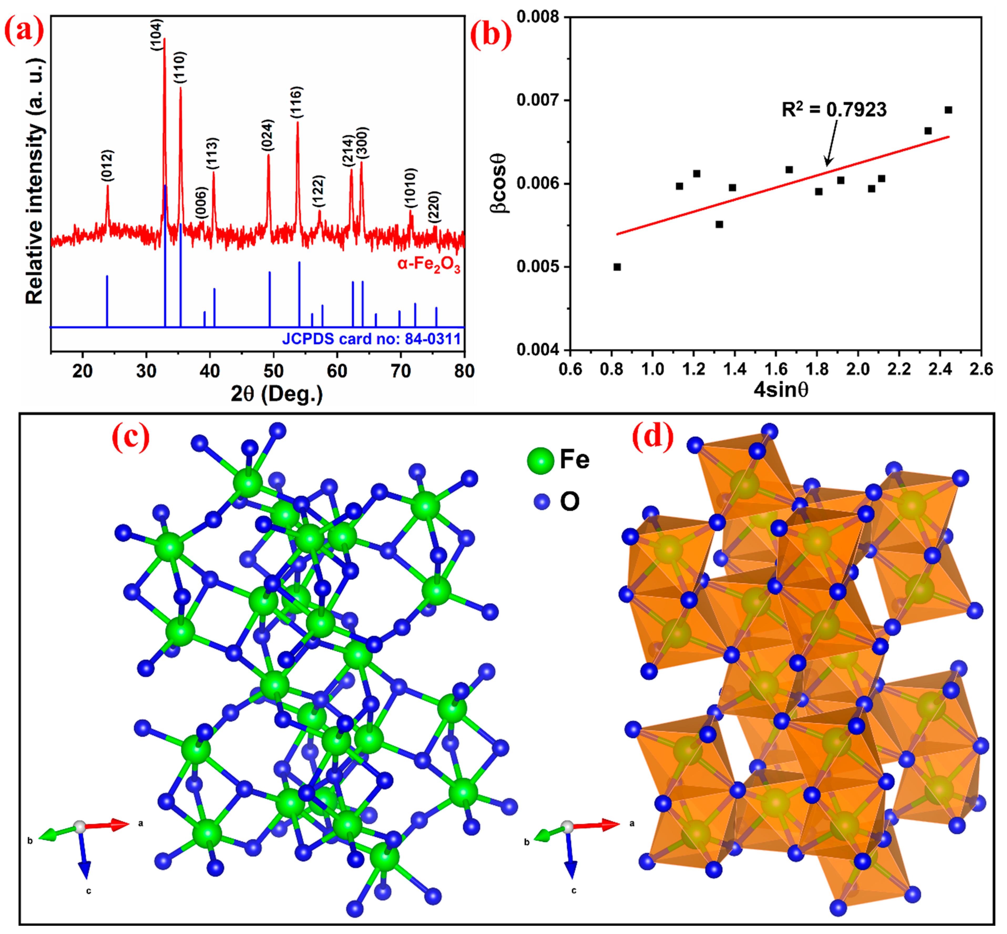
Figure 1. (a) Powder XRD pattern of the synthesized α-Fe2O3 NPs. The Rhombohedral crystal structure of α-Fe2O3 drawn by Vesta software (Version 3.4.5). (b) Williamson–Hall (W-H) plot for α-Fe2O3 NPs. (c) Ball-and-stick model of α-Fe2O3 crystal structure and (d) polyhedral model of α-Fe2O3 crystal structure. Unit cell lattice parameters: crystal system—Rhombohedral, space group—R-3c, distances a = b = 5.10485, c = 13.91330, along with axes (for Fe, x = 0.000000, y = 0.000000, and z = 0.145825 and O, x = 0.000000, y = 0.304877, and z = 0.750000), and angles α = β = 90°, γ = 120°.
Symmetry 15 01139 g001
Figure 2. FTIR spectrum of the α-Fe2O3 NPs.
Symmetry 15 01139 g002
Figure 3. SEM images at different magnifications (ac), histogram showing particle size distribution (d), and EDX spectrum (e) of α-Fe2O3 NPs.
Symmetry 15 01139 g003
Figure 4. (a) EDS mapping of the prepared α-Fe2O3 NPs, (b) overall elements distribution, (c) Fe distribution, and (d) O distribution.
Symmetry 15 01139 g004
Figure 5. DLS of the as-synthesized α-Fe2O3 NPs.
Symmetry 15 01139 g005
Figure 6. (a) UV–Vis absorbance spectrum of the synthesized α-Fe2O3 NPs and (b) the corresponding Tauc plot.
Symmetry 15 01139 g006
Figure 7. (a) Cyclic voltammetry and (b) Nyquist plot of the synthesized α-Fe2O3 NPs.
Symmetry 15 01139 g007
Figure 8. (a) UV–Vis spectrum of MB dye degradation in different time intervals. (b) Photodegradation efficiency. (c) Black line represents the photocatalytic degradation of MB dye without catalyst (blank test) and red line represents the photocatalytic degradation of MB dye with Fe2O3 catalyst and (d) kinetics plot.
Symmetry 15 01139 g008
Figure 9. Electron transfer and degradation mechanism for the photodegradation of MB using α-Fe2O3 catalyst under sunlight irradiation.
Symmetry 15 01139 g009
Disclaimer/Publisher’s Note: The statements, opinions and data contained in all publications are solely those of the individual author(s) and contributor(s) and not of MDPI and/or the editor(s). MDPI and/or the editor(s) disclaim responsibility for any injury to people or property resulting from any ideas, methods, instructions or products referred to in the content.