Abstract
As subsea shield tunnels are becoming increasingly popular, especially in coastal or river cities, the complicated construction environment poses multiple challenges that need to be addressed to ensure their safety and reliable operation. This study presents the results of centrifuge model tests that aimed to examine the impacts of navigable channel excavation and seawall construction on the deformation and forces acting on a subsea shield tunnel. The symmetry of the tunnel structure, as well as the loading and unloading effects from channel excavation and seawall construction in this engineering project, allow for the simplification of the problem. The centrifuge test model included a novel device to simulate the unloading action of channel excavation and the loading impact from seawall construction. The structural response of the tunnel was monitored using an innovative solution, and various parameters such as vertical displacement, opening of the circumferential joint, circumferential bending moment, and longitudinal stress were analyzed. The results reveal that both channel excavation and seawall construction have significant effects on the stress and deformation of the pre-existing tunnel. While the excavation of the navigable channel reduces the load on the tunnel from the overlying strata, resulting in uplifts in the tunnel structure around the excavation area, and the construction of the seawall causes settlement of the tunnel near the loading zone. The unloading effect of channel excavation leads to the opening tendency of the tunnel circumferential joints, while the loading effect of seawall construction has the opposite effect on the tunnel circumferential joints. The excavation of the channel induces tensile stresses on the tunnel crown around the loading zone, while the seawall construction causes significant compressive stresses on the tunnel crown around the loading zone. It is crucial to prioritize safety and ensure the tunnel’s load-bearing capacity through careful design and construction considerations in practical engineering. The study can guide the design and construction of future projects and help minimize the risk of damage to pre-existing structures.
1. Introduction
With the continuing advances in underground space development and tunnel construction technology, urban underground transportation infrastructure, such as railway tunnels, highway tunnels and metro tunnels, is undergoing a rapid increase [1,2]. The shield tunneling method has emerged as the preferred approach for urban tunnel construction due to its advantages, such as high safety, efficiency and mechanization ability, and minimal environment impact. In order to relieve congestion and improve the efficiency of transport between different parts of the city, many cities, especially some coastal or river cities, are currently undertaking or planning the construction of cross-river or underwater tunnels [3,4]. However, the construction of these tunnels faces complex challenges from high water pressure, large-diameter excavation surfaces, and intricate stratigraphic conditions. Moreover, during the operational phase following tunnel construction, the surrounding environment undergoes changes such as the excavation of superjacent waterways and the proximity of new tunnels, posing additional risks to tunnel structures, including deformation, distortion, induced stress, water infiltration, etc. [5,6].
The excavation and the removal of soil and rock around the tunnel can cause ground movements, resulting in tunnel uplift or settlement. Distortion of the tunnel can occur due to the deformation of the soil and rock around the tunnel [7,8]. Moreover, the excavation can cause additional stress on the tunnel, potentially leading to cracks and further structural damage. It can also lead to the infiltration of water into the tunnel, affecting the regular functionality and durability of the tunnel [9,10]. Relevant research on this subject is of vital importance and urgently needs to be addressed.
A number of studies have been conducted on the structural response of tunnels using various approaches, including theoretical analyses, numerical modeling, laboratory and field testing. Liang et al. [11] presented an analytical approach, treating the shield tunnel as a continuous Euler–Bernoulli beam on a Pasternak foundation model to investigate the impact of tunnel embedment depth. Zheng et al. [12] developed a simplified semi-empirical method of assessing the deformation of tunnels that are laterally adjacent to excavations. Mu et al. [13] developed a three-stage method for calculating the longitudinal deformation of tunnels induced by soil movements resulting from braced excavation. While theoretical calculations can offer valuable insights for assessments of structural response [14,15,16,17], the computational process can become exceedingly complex or even unsolvable in circumstances where the geological conditions and excavation affecting factors are intricate.
Numerical modeling techniques are crucial to resolving the nonlinear problem and many practical and effective modeling techniques have been developed regarding this issue [18,19,20]. Zheng and Wei [21] presented a two-dimensional finite-element (FE) analysis to examine the influence of excavating overlying basements on existing metro tunnels. Huang et al. [22] conducted a comprehensive parametric analysis to examine the behavior of tunnels influenced by nearby deep excavations. The study focused on investigating the impact of various factors on tunnel response. Chen et al. [23] performed three-dimensional numerical simulations to examine the response of an adjacent tunnel to basement excavation, tracking the displacement and bending moment of the existing tunnel at various stages of the excavation process. Shi et al. [24] developed a hybrid model based on 3D nonlinear contact theory and investigated the mechanical and deformation properties of the segments and joints of an existing shield tunnel when subjected to lateral excavation of the foundation pits, considering the non-continuous nature of the tunnel lining and the interactions among the tunnel segments, surrounding rocks, and ballast bed.
Many field tests and model tests, especially centrifuge model tests, were carried out under various conditions [25,26,27]. By creating equivalent stress levels as the full-scale prototype in a scaled-down model, centrifuge model testing offers a reliable means of simulating the response of tunnel structures under various external loads and evaluating their stress and deformation. Huang et al. [28] conducted a series of centrifuge model tests to investigate the effect of a deep excavation above an existing tunnel based on an underground passage project in the Bund, Shanghai, which intersects an existing shield tunnel. Ng et al. [29] conducted centrifuge tests to assess the effects of basement excavation on an existing tunnel in dry sand and presented the deformed shapes and bending moments along the transverse direction of the tunnel. Meng et al. [30] investigated the response of an existing tunnel to a nearby excavation in saturated kaolin clay through centrifuge testing. The research examined the long-term behaviors of both the ground and tunnel.
While most of the existing research focuses on evaluating the construction-induced effects of newly built tunnels, basements, or foundation pits in close proximity to pre-existing tunnels, little of the research investigated large-scale excavation above large-diameter subsea tunnels or ground loading scenarios. Furthermore, existing centrifuge model tests often involve pre-embedded excavation zones in the soil, which do not accurately replicate the complex conditions of channel excavation and seawall construction. Therefore, it is necessary to develop specific approaches for simulating channel excavation and seawall construction in centrifuge tests.
In this study, a centrifuge model test was conducted to study the effects of navigable channel excavation and seawall construction on a subsea shield tunnel blow. Tunnel structure and the loading and unloading of channel excavation and seawall construction in this engineering projects exhibit symmetry, allowing for the simplification of the problem. An innovative device has been designed to conduct the unloading action of the channel excavation and the loading action of the seawall construction. An ingenious solution for monitoring the structural response of the tunnel was designed. The effects of channel excavation and seawall construction on the deformation and forces of the subsea tunnel are investigated by means of centrifuge model tests. Tunnel structural performance parameters such as vertical displacement, hoop bending moment, longitudinal stress, and the opening of segment joints are monitored and analyzed. The findings of this study can guide the design and construction for future projects and help to minimize the risk of damage to pre-existing structures.
2. Centrifugal Model Tests
2.1. Project Overview
The Mawan Cross-Sea Passage project is located in the western region of the Nanshan Peninsula, Shenzhen City, on the eastern bank of the Pearl River estuary. The proposed project starts from the junction of Mawan Boulevard and Yueliangwan Boulevard, extends along Mawan Boulevard in the Qianhaiwan Port Area and Jingang Boulevard in the Dachan Bay Port Area, and ends at the Dachan Bay Interchange of Guangshen Coastal Expressway, as shown in Figure 1. The total length of the passage is about 7.3 km, of which the Sea Section (shield tunnel) is about 1.1 km. The tunnel was excavated by large-diameter slurry tunnel boring machines. A circular section was adopted with an inner diameter of 13.7 m and an outer diameter of 15.0 m, and the width of the segment ring was 2.0 m. Moreover, the surrounding ports and land transportation plans are abundant. According to the current situation and long-term planning of the Qianhai Bay approach channel, excavation of the channel and construction of the seawall may be necessary to meet the navigation conditions of large cargo ships after project completion.
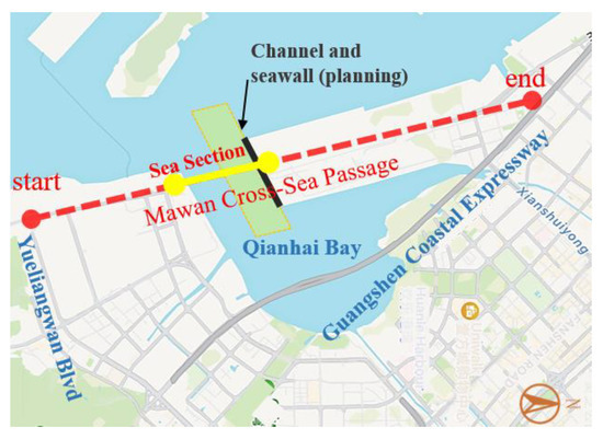
Figure 1.
Overview of the project.
2.2. Test Platform and Container
The test was carried out by the large-scale geotechnical centrifuge of Tianjin Research Institute for Water Transport Engineering M.O.T. (TIWTE) in China, as shown in Figure 2. It has a maximum centrifugal acceleration of 250 g and a maximum rotational radius of 5 m. It can test physical models up to 1.4 m in length, 1.5 m in width and 1.5 m in height. The TIWTE geotechnical centrifuge has been used to investigate a wide range of geotechnical problems, such as soil–structure interaction, slope stability, retaining walls, and deep foundations.
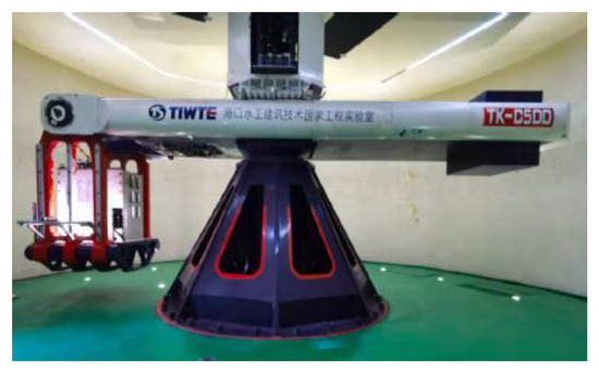
Figure 2.
Overview of the centrifuge.
A steel container was adopted as model box to ensure that it can withstand the centrifugal forces during the test without deforming or breaking. The size of the container was limited to 1.10 m in length, 0.50 m in width, and 0.77 m in height to accommodate the excavation and loading robots situated around the container. The configuration of the container is depicted in Figure 3.
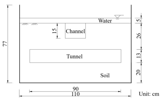
Figure 3.
The configuration of the container.
2.3. The Centrifuge Robot System
The physical models used in geotechnical centrifuge testing are small in scale, making it difficult to accurately reproduce the processes of channel excavation and seawall construction by manual operation. Moreover, the test container rotates at high speeds along with the centrifuge machine during the testing process, without the possibility of manual operation on the container. As a result, the simulation of these processes can only be achieved through the use of mechanized equipment, which can be fixed onto the basket of the centrifuge machine and remotely controlled. To address this challenge, a novel robotic device for centrifugal testing has been developed to achieve the unloading and loading actions involved in channel excavation and seawall construction.
The centrifuge robot system (CRS) comprises three main components: a moving platform (MP), an excavator (E), and a control cabinet (CC), as shown in Figure 4. The moving platform (MP) consists of a base frame, guide rails, moving racks, and controlling motors, and allows for movement in three degrees of freedom along the X, Y, and Z axes. Three independent motors are responsible for controlling the motion in each of these directions. The excavator (E) comprises a motor, two independent buckets, and connecting rods, and is affixed to the end of the Z-axis moving racks. The connecting rod connects the bucket to a threaded rod, which is operated by a motor that drives it to rotate, thereby controlling the opening and closing of the buckets. Through precise control of the excavator’s motion in the X, Y, and Z directions and the opening/closing of the buckets, this centrifuge robot system can accurately remove soil from targeted locations, thus achieving the excavation of channels. The loading effect of shore wall construction is simulated by placing a steel plate of appropriate weight in the corresponding position of soil mass.
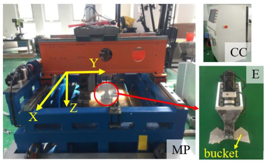
Figure 4.
The centrifuge robot system (CRS).
2.4. Tunnel Model
The setting of physical model size and the selection of similar model materials are the two most important factors in the design of a model tunnel. The experiments were designed to meet relevant similarity laws, including geometric similarity, kinematic similarity, and dynamic similarity. This ensured that important parameters such as length, acceleration, force, density, stress, strain, bending moment, and flexural rigidity were conserved throughout the tests [31,32]. These parameters, along with the corresponding scaling factors, are listed in Table 1.

Table 1.
Similarity law of the centrifugal model test.
According to similarity laws, when a reduced-scale model is constructed by reducing its length by a factor of N while simultaneously increasing the gravity (acceleration) by the same factor N, the stress within the model is equivalent to that anticipated within the prototype. Taking into account the size limitations of the test equipment and the container, geometric similarity ratio for this centrifuge test was chosen as 1:100, with an acceleration of 100 g in the centrifuge machine, which means that the stress in the model is the same as it would be in the prototype.
Additionally, the selection of similar materials is critical to ensure that the material parameters of the model and prototype are proportional, thereby ensuring consistent stress conditions under similar circumstances. The prototype tunnel segments are made of C50-reinforced concrete with an elastic modulus of 34.5 GPa. Based on material similarity requirements such as density and elastic modulus, the tunnel model should be made of C50 reinforced concrete, which is identical to the prototype material. However, this could cause several problems. The thickness of the concrete model segments, calculated according to the geometric similarity ratio, was only 6.5 mm, which makes it too weak and structurally unsound. Additionally, using concrete material for the model tunnel would be unfavorable to the structural assembly process and could result in compressive crushing failure during centrifuge tests. Therefore, it became clear that an alternative material was required. Given that the stiffness of the tunnel structure was the primary factor affecting the structural response, the principle of equivalent stiffness similarity was employed to select an alternative material. A magnesium–aluminum alloy (AZ31B) was chosen as its density and Poisson’s ratio are similar to that of the prototype reinforced concrete, but it is more compact and uniform in its structure and properties. The thickness of the magnesium–aluminum alloy model segment was calculated to be 14 mm by Equation (1), and a thickness of 15 mm was ultimately selected for the test to provide an additional safety margin. The model tunnel comprises 10 rings, each composed of 6 segments joined together by bolts. The outer diameter of the tunnel is 13 cm, while the inner diameter is 10 cm. Each ring is 90 m wide. The physical tunnel model is shown in Figure 5.

Figure 5.
Physical tunnel model.
2.5. Model Soil
The main purpose of the test is to study the mechanical properties of the segment lining structure. The soil mass is mainly used to simulate the earth pressure load on the tunnel. The prototype soil of this project is mainly dense fine sand, which is replaced by standard fine sand in the test. The composition of the strata in a tunnel can be complicated, making it difficult to accurately simulate the tunnel. As the surrounding strata mostly consists of clay and weathered granite, it is necessary to properly simplify the simulation process. Since obtaining seabed soil samples can be difficult and expensive, the typical strata of gravel clay in the Shenzhen area were used for modeling purposes. The relevant soil parameters for this approach are provided in Table 2.
Table 2.
Soil parameters.
3. Test Procedures and Monitoring Plan
3.1. Test Procedures
The testing procedure comprised four main steps:
(a) Model box preparation: The bottom of the box was filled with a layer of soil, and the displacement sensors were placed at the designed positions. The model tunnel was determined and buried, and soil was compacted and layered to a specified height. The process of preparing the model box is shown in Figure 6. Water was added to consolidate the soil before lifting the model box into the centrifuge basket.
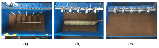
Figure 6.
The processes of preparing the model box: (a) determine the position of displacement sensors; (b) secure the tunnel in place; (c) fill the soil to the planned height.
(b) Excavation of navigable channel: The mechanical arm was calibrated, and the centrifuge was started and gradually increased to 100 g acceleration. The ground and tunnel structure were allowed to stabilize before the navigable channel was excavated according to the designated conditions and the data were collected. The channel was excavated in three layers. The excavation depth of each layer is 50 mm, and the cumulative excavation depth is 150 mm. Each layer is divided into 6 excavation areas, which are excavated in sequence from A to F, as shown in Figure 7. The centrifuge speed was then gradually reduced until it stopped.

Figure 7.
Physical tunnel model.
(c) Seawall construction loading test: After the excavation, the excavator was removed, and the loading plate was installed. The centrifuge was started and gradually increased to 100 g acceleration. Once stabilized, a designated load was applied to the seawall construction loading area through the loading plate, as shown in Figure 7, and the data were collected. The centrifuge speed was gradually reduced until it stopped.
(d) Model box dismantling and observations: The model box was lifted, and the test equipment was dismantled. The navigable channel excavation and the tunnel structure were observed, and a thorough check was performed.
3.2. Monitoring Design
In order to comprehensively and accurately evaluate the effect of navigable channel excavation and seawall construction on the response of tunnel structure, a detailed monitoring plan was developed for the experiment. The monitored parameters included:
- (a)
- Vertical displacement
The excavation of a navigable channel results in a reduction in the thickness of the soil layer covering the tunnel, leading to a decrease in the vertical load borne by the tunnel. Such changes in the load-bearing conditions may cause a certain degree of uplift to the tunnel. To monitor the vertical displacement of the tunnel structure, pull-rope displacement sensors were adopted in the tests. These sensors were installed in a fixed position on the container and the pull ropes moved through the protection tubes and were fastened to specific monitoring points (L1~L5) on the tunnel through metal rings, which were arranged along the longitudinal direction of the tunnel, as shown in Figure 8.
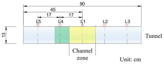
Figure 8.
The layout of the vertical displacement sensors.
- (b) Opening of circumferential joint
The opening of the circumferential joint is the distance between the two edges of a joint in the circumferential direction, and it can affect the overall stability and performance of the tunnel lining system. Waterproofing is crucial for subsea tunnels. The uplift caused by excavation may cause a certain amount of opening at the circumferential joint, which can affect its waterproofing performance. At present, there is a lack of specialized testing equipment to measure the opening of joints in tunnel segments during centrifuge test, and it is not feasible to directly attach strain gauges to these joints for direct measurement. In the test, aluminum sheets of fixed length were firmly pasted between adjacent segments, and strain gauges were installed on the aluminum sheets. Therefore, the opening of circumferential joint is indirectly obtained through the strain of the aluminum sheet. The layout of the measuring points for opening circumferential joints is shown in Figure 9.
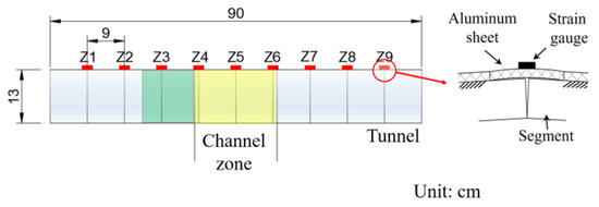
Figure 9.
The layout of the measuring points for the opening of circumferential joints.
- (c) Circumferential bending moment
The bending moment of a tunnel lining is the internal force induced in the lining structure due to external loads acting on it. This can cause the lining to deform or bend, which can affect its stability, integrity, and performance. The proper assessment and management of the bending moment in a tunnel lining is crucial for ensuring the safety and reliability of the tunnel, as well as optimizing its design and performance. To effectively monitor the development of internal force of the tunnel structure during centrifuge testing, strain gauges were attached to the inner and outer sides of the top of each segment. Additionally, to capture the distribution of hoop bending moment, five extra monitoring points were set along the hoop at the sixth ring (section 1-1), bringing the total number of monitoring points to 15. The arrangement of these circumferential bending moment monitoring points (from W1 to W15) is illustrated in Figure 10.
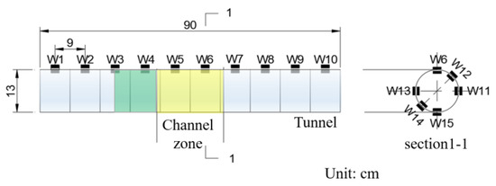
Figure 10.
The layout of the circumferential bending moment monitoring points.
- (d) Longitudinal stress
The stress is a direct reflection of the load-bearing condition of the tunnel structure. When the stress exceeds the strength of concrete segments, it may lead to concrete cracking and structural deformation, and even threaten the safety and integrity of the structure. To monitor the longitudinal stress in centrifuge testing, six strain gauges were arranged along the longitudinal direction of the tunnel, at the outside top of the tunnel. The arrangement of these sensors is shown in Figure 11.
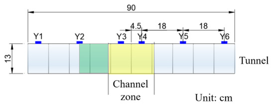
Figure 11.
The layout of the longitudinal stress monitoring points.
4. Test Results
4.1. Vertical Displacement
The vertical displacement of the tunnel crown is shown in Figure 12. From the first layer of excavation of the channel, the tunnel showed a certain uplift trend (positive values indicate upward displacement), and the vertical displacement of the tunnel further increased as the second and third layers of soil were excavated. The maximum uplift value of the tunnel after the first layer of excavation was about 11 mm, and after the second layer of excavation, the maximum uplift value was about 15 mm. The final uplift value of the tunnel after excavation was about 22 mm. The loading plate was used to apply a load, and the loading period lasted for a total of 988 seconds. As a result of the loading effect from the seawall construction, the displacement of the tunnel near the loading area gradually decreased, and finally, settlement appeared around the loading area, with a maximum settlement value of about 5 mm. The maximum uplift value during excavation was reduced to 12 mm due to the effect of loading. The vertical displacement of the tunnel on the non-loading side of the channel remained relatively stable, indicating that it was less affected by loading.
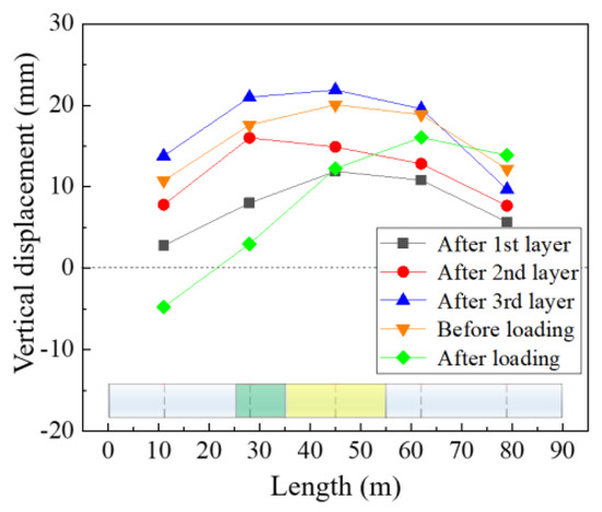
Figure 12.
Vertical displacement of the tunnel.
At the same time, it should be noted that the outermost monitoring point also showed some uplift during the excavation. On the one hand, due to the limited size of the model box, the length of the tunnel is not sufficient to completely eliminate the influence of boundary conditions. Even at the edge of the model tunnel, displacement cannot reach zero. On the other hand, the model tunnel structure is simplified compared to the actual engineering tunnel, and the width of the segments is increased to a certain extent, which increases the tunnel structure’s ability to transmit internal forces and deformations longitudinally. In addition, it was observed that the vertical displacement of the tunnel before the seawall construction was slightly smaller than that after the completion of the third layer of excavation of the channel. This can be attributed to the interruption in centrifuge operation that occurred during the transition phase. Specifically, the centrifuge was temporarily halted to remove the excavator and install the loading plate. Subsequently, the centrifuge was restarted, and as it stabilized at an acceleration of 100 g, a minor change in the vertical displacement of the tunnel had already occurred.
4.2. Opening of Circumferential Joint
Figure 13 shows the opening of circumferential joint at different test stages. During the excavation, the circumferential joints at the top of the tunnel within the tunnel excavation zone show a more obvious opening compared with the non-excavation portion on both sides of the channel. As more layers were removed, the amount of opening continued to increase, and the maximum opening reached nearly 2.0 mm when the excavation was complete, located at the channel excavation center (Z5). The further from the excavation center, the smaller the opening of circumferential joint. There was also a certain opening, which implied the influence of the boundary effect in the test. After the loading of construction, the opening at the center of the loading zone (Z3) decreased significantly from 1.8 mm to 0.7 mm. The opening of the joints on both sides away from the loading center (Z1, Z2, Z4 and Z5) also decreased to a certain extent, and the reduction value of the opening decreased as the distance between the monitoring point and the excavation center increased. On the other side of the tunnel (Z6, Z7, Z8), away from the loading zone, the opening showed no significant change. It can be concluded that both channel excavation and seawall construction have significant effects on the opening of circumferential joint of the tunnel. The unloading effect of channel excavation leads to the opening tendency of tunnel circumferential joints, while the loading effect of seawall construction has the opposite effect on tunnel circumferential joints.
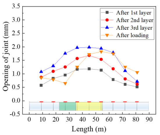
Figure 13.
Opening of circumferential joint of the tunnel.
4.3. Circumferential Bending Moment
The circumferential bending moment at the tunnel crown during different stages of the test is shown in Figure 14. Initially, the tunnel crown experienced a large bending moment of about 800 kN·m due to soil and water pressure. With the excavation of the channel, the crown bending moments showed a decreasing trend. The bending moment decreased more significantly as the monitoring point grew longitudinally closer to the middle of the channel. The minimum bending moment at the tunnel crown occurred near the excavation center, while the reduction in bending moment on both sides away from the excavation center was not significant. The bending moment at the tunnel crown near the excavation center decreased to 480 kN·m after the excavation of the first layer, dropped to 420 kN·m after the second layer, and further reduced to approximately 180 kN·m after the third layer. The main reason for the decrease in bending moment is that the channel excavation reduced the overlying load on the tunnel, thereby reducing the internal forces of the structure. This is advantageous from the perspective of preventing the failure of the segment structure. With the construction of the seawall, a notable increase in the bending moment at the tunnel crown near the loaded area was observed, surpassing the initial level prior to the channel excavation. This can be attributed to the additional load imposed on the tunnel due to the seawall construction, which exceeded the original strata load under pre-excavation conditions. In contrast, on the other side of the tunnel, where no loading was performed, there was no significant change in the bending moment at the tunnel crown.
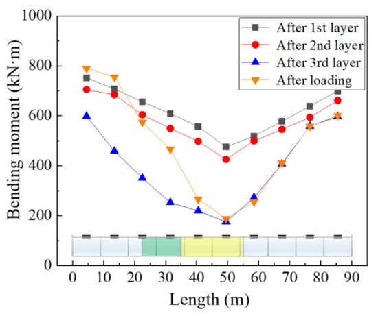
Figure 14.
Circumferential bending moment of the tunnel.
Figure 15 shows the distribution of the circumferential bending moment of the tunnel (section 1-1) near the channel excavation center. The maximum bending moments occur at the top or bottom of the tunnel. The bending moments at different positions of tunnel segment ring decrease to different degrees as the unloading effect of excavation with the bending moments at the top (crown) and bottom (invert) of the tunnel decrease more significantly than those of the middle part of the tunnel (waist).
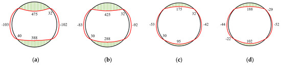
Figure 15.
Circumferential bending moment of section 1-1: (a) after 1st layer; (b) after 2nd layer; (c) after 3rd layer; (d) after loading; unit: kN·m.
4.4. Longitudinal Stress
Figure 16 shows that, in the range of the channel excavation (Y3 and Y4), tensile stress existed on the outer side of the tunnel crown with the maximum value appearing near the center of the excavation area. At both ends of the tunnel (Y1 and Y6), the outer side of the tunnel crown experienced longitudinal compressive stress. In the area of the seawall construction (Y2), the tunnel crown experienced tensile stress during the excavation and the tensile stress was less than 0.5 MPa. After the loading of seawall construction, the stress at the outer side of the tunnel crown near the loading center changed to compressive stress with a value of about 4.5 MPa. Meanwhile, the tensile stress at some parts of tunnel (Y4) in the excavation area further increased.
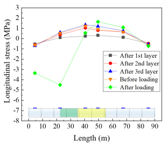
Figure 16.
Longitudinal stress of the tunnel.
5. Analysis and Discussion
Centrifuge model tests can effectively reproduce the stress levels, thus providing a more realistic representation of the structural and displacement response of tunnels under external loads. However, due to the limitations of objective conditions during testing, simplifications and compromises are often made to the test schemes, which may have an impact on the test results. Therefore, it is necessary to interpret and verify the test results through theoretical calculations or numerical analysis.
In actual engineering, the geological conditions where tunnels are located are generally not a single layer, but rather complex. However, a single soil layer was used in this test, which simplifies the testing conditions. To enable effective monitoring of the tunnels’ structural responses, the physical model should be as large as possible for ease of operation. However, due to the limitations of the centrifuge bearing capacity and the space of the suspension basket, the model box and physical model are usually small. This makes it difficult to process and assemble the tunnel structure, and the physical model of the tunnel also needs to be simplified, which may lead to differences compared to the actual engineering. Furthermore, this brings significant limitations to the setting of cases, loads, and boundary conditions in the tests. In this experiment, if the range of excavation and bank construction is too small, its impact on the tunnel structure cannot be fully reflected. If the range of excavation and bank construction is too large, it is difficult to completely eliminate the influence of boundary conditions due to the limited size of the model box and the length of the tunnel. All these factors could have an impact on the test results.
In order to provide an evaluation of the experimental results and account for possible errors introduced by the above factors, a comparison was conducted between our findings and relevant research from the literature. Chen et al. [33] conducted a similar study using finite element method (FEM) numerical simulation techniques, which closely resembled these research conditions in terms of tunnel depth, dimensions, structural parameters, and geological conditions. The primary differences were in the width of the channel (20 m in this study, 120 m in their study) and the width of the seawall (15 m in this study, 20 m in their study). While their study focused on the displacement and stress of the tunnel structure, it did not investigate the opening of segment joints and circumferential bending moment. In the following discussion, we compare their simulation results with our results.
Moreover, to provide a more comprehensive comparative analysis, we also established a numerical model with the same excavation and unloading conditions as the centrifuge model test. The dimensions of the numerical model were set as 300 m × 100 m × 80 m. For the geological layers, we adopted the Mohr–Coulomb model, with parameters consistent with those of the soil model used in the physical experiments. The tunnel structure was represented by shell elements, with dimensions matching those of the actual engineering project. The sides and bottom were fixed, while the other sides were assigned free boundaries. The channel excavation was conducted in three stages, followed by the loading of the seawall construction. To ensure model stability after excavation, 45-degree slopes were adopted on both sides of the channel. The seawater load was simulated by applying a uniformly distributed load. After the channel excavation, additional seawater loads were applied in the excavation zone to simulate the load of seawater that replaces the earth within the excavation zone (Figure 17).
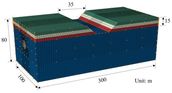
Figure 17.
Overview of the numerical model.
The vertical displacement, circumferential bending moment and longitudinal stress of the tunnel structure were analyzed and compared with the results of the centrifugal test, as shown in Figure 18.
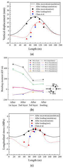
Figure 18.
Comparison between numerical simulation and model test: (a) vertical displacement; (b) bending moment; (c) longitudinal stress.
It can be seen in Figure 18a that the vertical displacement of the tunnel obtained from numerical simulation exhibits a consistent trend with the centrifuge test results. A comparison between two studies revealed that the value at the excavation center from Chen et al. was relatively close to that in our study, with both being around 10 mm, while the difference between the two studies increased slightly at the seawall center. Overall, the experimental results were in better agreement with the numerical simulations in this study, which can be attributed to the closer resemblance of the experimental conditions to the numerical model. We also noticed that the results of the numerical calculation are slightly higher than those of the centrifuge test. The main reason for the overall upward movement of the tunnel in the centrifugal model test is the size limitation of the centrifugal model box, as the mode tunnel is not long enough to eliminate the influence of the boundary effect. It can be seen that the length of the tunnel section for which displacement was affected by the excavation was 200 m. Additionally, in actual engineering projects, the tunnel is often assembled with many segments, which allows for more flexibility, better coordination and better adaptation to ground deformation. In practical engineering projects, tunnels are typically constructed using numerous segments, allowing for greater flexibility and better coordination to accommodate ground deformations. In contrast, the experimental setup divided the tunnel structure into nine segment rings and there were fewer segments within each ring. While this increased the overall stiffness of the structure, it compromised its ability to respond to deformations in a coordinated manner. This difference may contribute to the disparity between the experimental results and the actual conditions.
The circumferential bending moment of the tunnel near the center of the navigation channel is shown in Figure 18b. Overall, the numerical simulation and centrifugal test results show a consistent trend, with the centrifugal test results being slightly larger. The distribution of circumferential bending moment shows that the maximum bending moment is at the crown and invert of the tunnel, and the bending moment decreases during the navigation channel excavation. The main reason for this is the reduction in overburden load on the tunnel, which is more favorable for the stress of the tunnel. However, during the loading of seawall construction, the bending moment shows an increasing trend. As mentioned earlier, the impact range is mainly concentrated on the construction side of the navigation channel. The loading effect caused by the seawall construction exceeds the unloading impact of the channel excavation. The impact range and degree are related to the scale of the excavation and the construction projects and its impact on the structure is complex. Therefore, during the specific structural design, special attention should be paid to this section, focusing on construction conditions, and relevant structural safety calculations should be carried out.
Figure 18c presents the longitudinal stress on the outer side of the crown of the tunnel. The overall consistency between the two studies’ results provides some validation of the accuracy of the experimental findings. In the excavation center, Chen’s results were smaller, primarily due to differences in tunnel structure and experimental conditions. Chen’s study had a wider excavation width, resulting in smoother variations in tunnel displacement around the excavation center, and therefore generating relatively lower additional stress in the structure. In comparison, our experiment was constrained by the size of the model box, preventing further extension in the excavation width and the length of the tunnel structure, which had some impact on the experimental structure. Moreover, the numerical simulation result is generally consistent with that from the centrifuge model test. In the range of the channel excavation, the concrete on the outer side of the crown experiences tensile stress, with the maximum value appearing near the center of the excavation area. At both ends of the tunnel, the concrete on the outer side of the crown experiences compressive stress. After loading the seawall construction, the outer-side concrete of the crown near the loading center experiences significant compressive stress. This is consistent with the development of stress that is theoretically induced by tunnel deformation. The results show that the maximum tensile stress and compressive stress on the crown do not exceed the ultimate tensile strength and ultimate compressive strength of concrete, indicating that there is no cracking of concrete segments in practical engineering. In addition, it is notable that the discrepancies between the simulation results and test results are more obvious at the outermost measurement points (around 60 m and 140 m), compared to the other four measurement points. This can be attributed to the limitations of the centrifuge model box, which restrict the length of the tunnel section experiencing displacement due to excavation.
6. Conclusions
In order to study the effects of navigable channel excavation and seawall construction on a subsea shield tunnel right blow, a centrifuge model test was conducted in this paper. Innovative equipment was used in the test to simulate the channel excavation (unloading) and the seawall construction (loading). A creative method was developed to track the opening of the tunnel joints. Aspects of tunnel structural performance such as vertical displacement, bending moment, longitudinal stress and the opening of segment joints were monitored and analyzed. The test results were analyzed and discussed. The following conclusions can be drawn.
- (1)
- Both channel excavation and seawall construction have significant effects on the stress and deformation of the pre-existing tunnel. Channel excavation will reduce the load of the overlying strata on the tunnel, and then lead to the uplift of the tunnel structure around the excavation area, while the construction of the seawall will cause the settlement of the tunnel structure near the loading zone, which is contrary to the effect of channel excavation.
- (2)
- After the excavation, the circumferential joints at the top of the tunnel inside the excavation zone show more obvious openings than those on the either side of the tunnel, which are outside the excavation zone. The maximum opening reached nearly 2.0 mm in the test. After the seawall construction, the opening at the center of the loading zone decreased significantly. Overall, the unloading effect of channel excavation leads to the opening tendency of the tunnel circumferential joints, while the loading effect of seawall construction has the opposite effect on the tunnel circumferential joints.
- (3)
- While the excavation of the navigable channel can reduce the bending moment of the tunnel crown and invert around the excavation zone, the construction of the seawall can increase the bending moment around the loading area and even cause it to exceed the initial bending moment value, which can be unfavorable for segments. The change in tunnel structural stress is the combined result of these two effects. This suggests that additional attention should be paid to the safety and load-bearing capacity of the tunnel during design and construction in practical engineering.
- (4)
- The excavation of the channel will cause tensile stresses on the tunnel crown around the excavation zone, with the maximum tensile stress occurring at the excavation center, while the tunnel some distance from the excavation center will experience compressive stresses. The seawall construction causes significant compressive stresses on the tunnel crown around the loading zone. The maximum tensile stress and compressive stress do not exceed the ultimate tensile and compressive strengths of the concrete, indicating that there is no cracking of the concrete segments.
- (5)
- The comparison of the numerical simulation results with the centrifuge test results indicates that the simplification of test conditions and the dimensional limitations of the physical model in the centrifuge tests may have an impact on the test results. In addition, the limited range of excavation and bank construction in the model tests can also affect the test results. It should be noted that the results presented in this article are based on specific project conditions. The specific calculation and analysis of actual engineering conditions should be considered when the findings of this study are applied to different projects.
Author Contributions
Conceptualization, X.W., D.Y. and W.L.; methodology, X.W., D.Y. and W.L.; software, X.W., W.L., S.Z. and H.L.; validation, X.W. and D.Y.; formal analysis, X.W., W.L. and S.Z.; investigation, X.W., D.Y. and H.L.; resources, D.Y., S.Z. and H.L.; data curation, X.W., W.L. and S.Z.; writing—original draft preparation, X.W.; writing—review and editing, X.W., D.Y. and W.L.; visualization, X.W. and H.L.; supervision, D.Y.; project administration, D.Y.; funding acquisition, D.Y. All authors have read and agreed to the published version of the manuscript.
Funding
This research was supported by the National Natural Science Foundation of China (Grant No. 52278389), Shandong Provincial Key Research and Development Program (Grant No. 2021CXGC010209), and the projects: Green and Safe Control Methods for Shield Tunneling in Complex Strata in Spring-Rich Area (Grant No. 2020-K-142, Grant No. 2020-Z2-1).
Institutional Review Board Statement
Not applicable.
Informed Consent Statement
Not applicable.
Data Availability Statement
The data presented in this study are available from the corresponding author upon request.
Conflicts of Interest
The authors declare no conflict of interest.
References
- Dai, H.; Ji, Y. Statistical Analysis of Chinese Large Diameter Shield Tunnel and State of Art and Prospective of Comprehensive Technologies. Tunnel Constr. 2022, 42, 757–783. [Google Scholar] [CrossRef]
- Jin, D.; Yuan, D.; Liu, S.; Li, X.; Luo, W. Performance of existing subway tunnels undercrossed by four closely spaced shield tunnels. J. Perform. Constr. Facil. 2019, 33, 04018099. [Google Scholar] [CrossRef]
- Eisenstein, Z.D. Large undersea tunnels and the progress of tunnelling technology. Tunn. Undergr. Space Technol. 1994, 9, 283–292. [Google Scholar] [CrossRef]
- Hong, K. Typical underwater tunnels in the mainland of China and related tunneling technologies. Engineering 2017, 3, 871–879. [Google Scholar] [CrossRef]
- Wang, M.S. Current developments and technical issues of underwater traffic tunnel—Discussion on construction scheme of Taiwan strait undersea railway tunnel. Chin. J. Rock Mech. Eng. 2008, 27, 2161–2172. Available online: https://www.oalib.com/paper/1484071 (accessed on 9 June 2023).
- Morris, M.; Yang, M.W.; Tsang, C.K.; Hu, A.Y.; Shut, D.S. An overview of subsea tunnel engineering in Hong Kong. Proc. Inst. Civ. Eng. Civ. Eng. 2016, 169, 9–15. [Google Scholar] [CrossRef]
- Zhang, Z.; Huang, M.; Wang, W. Evaluation of deformation response for adjacent tunnels due to soil unloading in excavation engineering. Tunn. Undergr. Space Technol. 2013, 38, 244–253. [Google Scholar] [CrossRef]
- Harahap, S.E.; Ou, C.Y. Finite element analysis of time-dependent behavior in deep excavations. Comput. Geotech. 2020, 119, 103300. [Google Scholar] [CrossRef]
- Doležalová, M. Tunnel complex unloaded by a deep excavation. Comput. Geotech. 2001, 28, 469–493. [Google Scholar] [CrossRef]
- Meng, F.Y.; Chen, R.P.; Wu, H.N.; Xie, S.W.; Liu, Y. Observed behaviors of a long and deep excavation and collinear underlying tunnels in Shenzhen granite residual soil. Tunn. Undergr. Space Technol. 2020, 103, 103504. [Google Scholar] [CrossRef]
- Liang, R.; Wu, W.; Yu, F.; Jiang, G.; Liu, J. Simplified method for evaluating shield tunnel deformation due to adjacent excavation. Tunn. Undergr. Space Technol. 2018, 71, 94–105. [Google Scholar] [CrossRef]
- Zheng, G.; Yang, X.; Zhou, H.; Du, Y.; Sun, J.; Yu, X. A simplified prediction method for evaluating tunnel displacement induced by laterally adjacent excavations. Comput. Geotech. 2018, 95, 119–128. [Google Scholar] [CrossRef]
- Mu, L.; Zhang, P.; Shi, Z.; Zhu, M.; Gu, Z. Predicting longitudinal tunnel deformation due to deep excavation-induced ground movement. Tunn. Undergr. Space Technol. 2023, 131, 104793. [Google Scholar] [CrossRef]
- Zhang, J.F.; Chen, J.J.; Wang, J.H.; Zhu, Y.F. Prediction of tunnel displacement induced by adjacent excavation in soft soil. Tunn. Undergr. Space Technol. 2013, 36, 24–33. [Google Scholar] [CrossRef]
- Cheng, K.; Xu, R.; Ying, H.; Lin, C.; Gan, X.; Gong, X.; Zhu, J.; Liu, S. Analytical method for predicting tunnel heave due to overlying excavation considering spatial effect. Tunn. Undergr. Space Technol. 2023, 138, 105169. [Google Scholar] [CrossRef]
- Liu, J.; Shi, C.; Lei, M.; Cao, C.; Lin, Y. Improved analytical method for evaluating the responses of a shield tunnel to adjacent excavations and its application. Tunn. Undergr. Space Technol. 2020, 98, 103339. [Google Scholar] [CrossRef]
- Cheng, H.; Chen, R.; Wu, H.; Meng, F. A simplified method for estimating the longitudinal and circumferential behaviors of the shield-driven tunnel adjacent to a braced excavation. Comput. Geotech. 2020, 123, 103595. [Google Scholar] [CrossRef]
- Sharma, J.S.; Hefny, A.M.; Zhao, J.; Chan, C.W. Effect of large excavation on deformation of adjacent MRT tunnels. Tunn. Undergr. Space Technol. 2001, 16, 93–98. [Google Scholar] [CrossRef]
- Hu, Z.F.; Yue, Z.Q.; Zhou, J.; Tham, L.G. Design and construction of a deep excavation in soft soils adjacent to the Shanghai Metro tunnels. Can. Geotech. J. 2003, 40, 933–948. [Google Scholar] [CrossRef]
- Liu, H.; Li, P.; Liu, J. Numerical investigation of underlying tunnel heave during a new tunnel construction. Tunn. Undergr. Space Technol. 2011, 26, 276–283. [Google Scholar] [CrossRef]
- Zheng, G.; Wei, S.W. Numerical analyses of influence of overlying pit excavation on existing tunnels. J. Cent. South Univ. 2008, 15, 69–75. [Google Scholar] [CrossRef]
- Huang, X.; Schweiger, H.F.; Huang, H. Influence of deep excavations on nearby existing tunnels. Int. J. Geomech. 2013, 13, 170–180. [Google Scholar] [CrossRef]
- Chen, R.; Meng, F.; Li, Z.; Ye, Y.; Ye, J. Investigation of response of metro tunnels due to adjacent large excavation and protective measures in soft soils. Tunn. Undergr. Space Technol. 2016, 58, 224–235. [Google Scholar] [CrossRef]
- Shi, C.; Cao, C.; Lei, M.; Peng, L.; Ai, H. Effects of lateral unloading on the mechanical and deformation performance of shield tunnel segment joints. Tunn. Undergr. Space Technol. 2016, 51, 175–188. [Google Scholar] [CrossRef]
- Huang, H.W.; Xu, L.; Yan, J.L. The longitudinal model test of shield tunnel. Tunn. Undergr. Space Technol. 2006, 21, 418–419. [Google Scholar] [CrossRef]
- Jin, D.L.; Yuan, D.J.; Wei, J.X.; Li, X.G.; Lu, P. Centrifugal model test of group tunneling with small spacing beneath existing tunnels. Chin. J. Geotech. 2018, 40, 1507–1514. Available online: https://www.researchgate.net/publication/328553648_Centrifugal_model_test_of_group_tunneling_with_small_spacing_beneath_existing_tunnels (accessed on 9 June 2023).
- Lu, P.; Yuan, D.; Jin, D.; Luo, W.; Liu, M. Centrifugal model tests on the structural response of the shield tunnel when constructing cross passages by mechanical methods. Tunn. Undergr. Space Technol. 2022, 128, 104621. [Google Scholar] [CrossRef]
- Huang, X.; Huang, H.; Zhang, D. Centrifuge modelling of deep excavation over existing tunnels. Proc. Inst. Civ. Eng. Geotech. Eng. 2014, 167, 3–18. [Google Scholar] [CrossRef]
- Ng, C.W.; Shi, J.; Hong, Y. Three-dimensional centrifuge modelling of basement excavation effects on an existing tunnel in dry sand. Can. Geotech. J. 2013, 50, 874–888. [Google Scholar] [CrossRef]
- Meng, F.Y.; Chen, R.P.; Liu, S.L.; Wu, H.N. Centrifuge modeling of ground and tunnel responses to nearby excavation in soft clay. J. Geotech. Eng. 2021, 147, 04020178. [Google Scholar] [CrossRef]
- Schofield, A.N. Cambridge geotechnical centrifuge operations. Geotechnique 1980, 30, 227–268. [Google Scholar] [CrossRef]
- Taylor, R.N. (Ed.) Geotechnical Centrifuge Technology; CRC Press: Boca Raton, FL, USA, 2003. [Google Scholar]
- Chen, X.; Tao, L.; Chen, X. Influence of channel dredging on subsea shield tunnel using FEM. In Proceedings of the 2015 4th International Conference on Sustainable Energy and Environmental Engineering, Shenzhen, China, 20–21 December 2016. [Google Scholar] [CrossRef]


Disclaimer/Publisher’s Note: The statements, opinions and data contained in all publications are solely those of the individual author(s) and contributor(s) and not of MDPI and/or the editor(s). MDPI and/or the editor(s) disclaim responsibility for any injury to people or property resulting from any ideas, methods, instructions or products referred to in the content. |
© 2023 by the authors. Licensee MDPI, Basel, Switzerland. This article is an open access article distributed under the terms and conditions of the Creative Commons Attribution (CC BY) license (https://creativecommons.org/licenses/by/4.0/).