Article

Effects of KoBo-Processing and Subsequent Annealing Treatment on Grain Boundary Network and Texture Development in Laser Powder Bed Fusion (LPBF) AlSi10Mg Alloy

by
Przemysław Snopiński
Department of Engineering Materials and Biomaterials, Silesian University of Technology, 18A Konarskiego Street, 44-100 Gliwice, Poland
Symmetry 2024, 16(1), 122; https://doi.org/10.3390/sym16010122
Submission received: 14 December 2023 / Revised: 17 January 2024 / Accepted: 18 January 2024 / Published: 19 January 2024
(This article belongs to the Special Issue Symmetry in Mechanical Engineering: Properties and Applications)

Abstract

:
It is well known that the properties of polycrystalline metals are related to grain boundaries (GBs), which are fundamental structural elements where crystallographic orientations change abruptly and often exhibit some degree of symmetry. Grain boundaries often exhibit unique structural, chemical, and electronic properties that differ from bulk crystalline domains. Their effects on material properties, including mechanical strength, corrosion resistance, and electrical conductivity, make grain boundaries a focus of intense scientific investigation. In this study, the microstructural transformation of an AlSi10Mg alloy subjected to KoBo extrusion and subsequent annealing is investigated. A notable discovery is the effectiveness of a strain-annealing method for grain boundary engineering (GBE) of the LPBF AlSi10Mg alloy. In particular, this study shows a significant increase in the population of coincidence site lattice boundaries (CSL), which embody the symmetry of the crystal lattice structure. These boundaries, which are characterised by a high degree of symmetry, contribute to their special properties compared to random grain boundaries. The experimental results emphasise the crucial role of strain-induced boundary migration (SIBM) in the development of a brass texture in the microstructure of the alloy after annealing. In addition, the presented results demonstrate the feasibility of applying GBE to materials with high stacking fault energy (SFE), which opens up new possibilities for optimizing their properties.

1. Introduction

Grain boundary engineering (GBE) is a processing strategy aimed at enhancing the properties of polycrystalline materials through the manipulation of grain boundaries (GBs) in terms of distribution and character. Originating from Watanabe’s concept of “GB design and control” in 1984 [1], GBE has become a powerful technique for improving inherent properties [2,3], particularly in face-cantered cubic metals with low to medium stacking fault energy (SFE) such as copper [4], nickel-based alloys [5], austenitic steels [6,7] and metal-matrix composites [8,9].
The core of GBE involves thermomechanical processing (TMP) to increase the prevalence of low-coincidence site lattice (CSL, Σ ≤ 29) boundaries, focusing on Σ3 boundaries (twin boundaries, TB) to disrupt random boundary connections [4]. Recent research has extended GBE to high-SFE materials like aluminium alloys. Shamanian et al. (2016) observed an increase in Σ3 boundaries during friction stir processing (FSP) of A413 cast aluminium alloy [10], and Jia et al. (2018) investigated the formation of Σ = 3{110} incoherent twin boundaries (ITBs) in an Al-8Zn alloy [11]. Similarly, Pradeep et al. (2021) studied AA5053 subjected to friction stir processing, reporting an increased percentage of Σ = 3n (n = 1, 2, 3) CSL boundaries [12].
In laser powder bed fusion (LPBF)-produced alloys, grain boundary character distribution (GBCD) modification often involves post-processing heat treatments. In this context, Li et al. treated an Inconel 718 superalloy produced by selective laser melting and found that the internal residual stress provides a sufficient activation energy for driving recrystallisation-based GBE during annealing. They produced an alloy with a high fraction of Σ3 GBs (64.89%) and a stable grain size [13]. In another study, Dong et al. [14] investigated a similar strategy based on isothermal annealing to modify GBCD in SLM Co-Cr alloy. They obtained a large fraction (more than 80%) of special boundaries (Σ3, Σ9, and Σ27) after complete recrystallisation.
An alternative GBE strategy involves plastic deformation followed by annealing. Such a method has been proposed as effective for SLM 304 austenitic stainless steel, for example, [15]. The authors of the cited manuscript found that laser peening followed by annealing at 1260 K for 48 h can lead to an optimal grain boundary character distribution with over 80 CSL%. An alternative approach was recently proposed by the author of this manuscript for the LPBF AlSi10Mg alloy [16]. It was shown that the grain boundary character distribution can be modified by post-processing during KoBo extrusion.
The KoBo-extrusion method is a severe plastic deformation (SPD) technique that enables deformation at a high strain rate. In this SPD method, the die is oscillated cyclically during the extrusion process, causing the deformation path to change continuously [17]. This unique deformation mode ensures a grain-refined structure without dislocation accumulation and work hardening. Another feature that distinguishes this technique from other SPD methods is the high plasticity of KoBo-processed metals, as it offers higher degree of deformation without the need for annealing treatment. This is because KoBo extrusion generates a large amount of heat, which intensifies the rearrangement of dislocations and the diffusion-controlled structural processes. As a result, materials with unique structural and mechanical properties can be produced [18,19].
In this paper, a novel post-processing approach to improve the special grain boundary population in the LPBF AlSi10Mg alloy is investigated. The LPBF sample is subjected to a two-step process involving high strain rate KoBo extrusion followed by annealing, which leads to a remarkable increase in the population of coincidence site lattice boundaries (CSL). These CSL boundaries, characterised by their unique crystal lattice symmetry, play a crucial role in the microstructural transformation of the alloy, which is particularly evident in the development of a distinct brass structure after annealing. The novelty lies in the limited research on GBE strategies for LPBF materials and in the application of the KoBo-extrusion process. Demonstrating the effectiveness of GBE on high stacking fault energy (SFE) materials, as observed in this study, opens up innovative possibilities for optimizing the properties of LPBF materials. Despite the known importance of GBE for controlling grain boundary character distribution (GBCD) and improving material properties, there is currently a knowledge gap in understanding GBE strategies for high-SFE materials, such as aluminium alloys, produced by LPBF. The results presented here aim to close this gap, representing the first investigation of GBE specifically tailored to aluminium alloys produced by LPBF.

2. Methodology

The specimens used in this experimental work were produced from an AlSi10Mg alloy powder via selective laser melting (SLM) with the following process parameters: laser power = 175 W; layer thickness = 20 μm; scanning speed = 1400 mm/s; and scan rotation = 67°. The cylindrically shaped samples had a total length of 50 mm and a diameter of 60 mm. Further details on the chemical composition and microstructural features of this alloy can be found in Refs. [20,21].
The SLM samples were post-processed via a KoBo-extrusion method, depicted in Figure 1, of which the principal description can be found in Ref. [22]. The extrusion process was conducted on a custom-made horizontal hydraulic press. The SLM samples were reversibly twisted with a constant angle of ±8° just before entering the die, where the cross section was reduced from 60 mm to 4 mm. The following process parameters were applied:
  • punch speed of 0.2 mm/s;
  • die rotation frequency of 5 Hz;
  • maximal measured temperature close to the extrusion die (~280 °C);
  • sample cooling with room-temperature water.
Following the KoBo-extrusion process, the midsection of the extruded profile was cut into 300 mm long segments that were then annealed in a resistance furnace for 1 h at 250 °C, 300 °C, 350 °C, 400 °C, 450 °C, or 500 °C under Ar atmosphere.
All specimens underwent the same metallographic preparation process with an automatic polishing machine LaboPol-20 (Struers, Copenhagen, Denmark) to ensure high surface quality. The material was first ground with 800 and 1200 grit SiC water paper, then polished with 6, 3, and 1 µm diamond pastes and finally mirror-polished with 0.04 μm colloidal silica suspension (OP-U suspension, Struers, Copenhagen, Denmark) for 1 h. The microstructure was characterised in detail via electron backscatter diffraction EBSD in a scanning electron microscope Zeiss Supra 35 (Carl Zeiss NTS GmbH, Oberkochen, Germany) equipped with an EDAX NT EBSD detector. EBSD scans were carried out on the sections perpendicular to the extrusion direction to evaluate the microstructural changes. Scans were registered in the centre area of the samples with a step size of 100 nm. TSL OIM Analysis 7 software was used to analyse the scanned raw data.
TEM analysis was performed in the Titan 80-300 FEI S/TEM microscope (Fei, Hillsboro, OR, USA), which was operated at 300 kV. To achieve ultra-thin lamellae suitable for HRTEM examination, ion milling was employed. Argon ions were used to selectively mill away material from the sample surface, gradually thinning the lamellae to ~80 nm. The TEM lamellae were extracted from the KoBo-processed sample along the extrusion direction.
The TEM lamella was additionally analysed via transmission Kikuchi Diffraction (TKD) to obtain crystallographic information that allowed characterisation of grain boundaries with improved resolution. The TKD map was acquired with a step size of 20 nm.

3. Results and Discussion

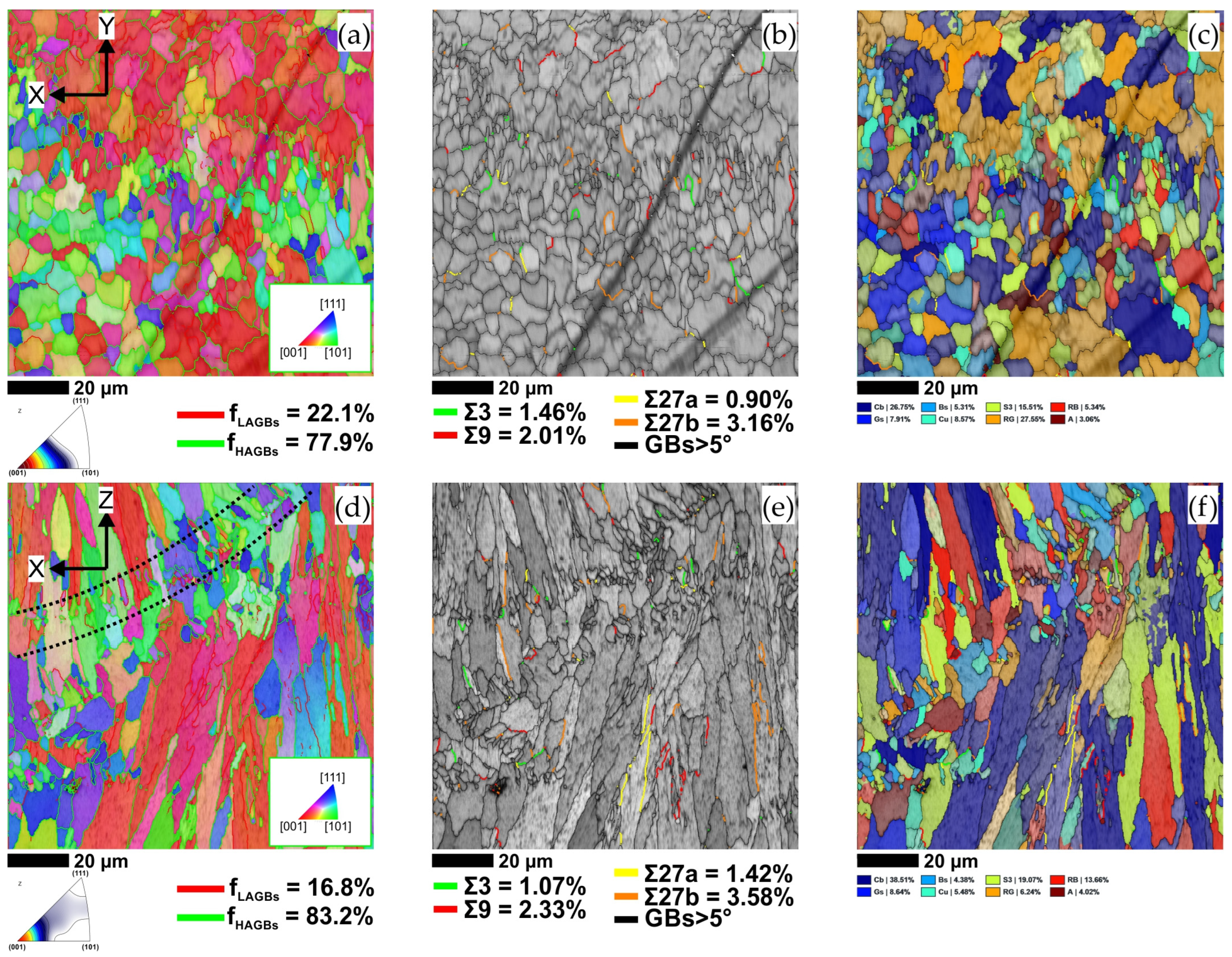
The main microstructural characteristics of the LPBF AlSi10Mg samples in the X–Y and X–Z planes were investigated using an EBSD technique. Figure 2a shows the inverse pole figure (IPF-Z) map taken in the X–Y plane. In this figure, the low-angle grain boundaries (LAGBs) with a misorientation angle (2° < θ < 15°) and the high-angle grain boundaries (HAGBs) with a misorientation angle (15° < θ < 65°) are represented by a red and green colour, respectively. As can be seen, the equiaxed grains with a preferred <001> crystallographic orientation dominated the alloy microstructure. According to statistical data, LAGBs accounted for 22.1% of the total boundary fraction, while HAGBs accounted for the remaining 77.9%. A grain boundary character-distribution map plotted based on the Brandon criterion is shown in Figure 2b. In this image, four main types (Σ3, Σ9, Σ27a, and Σ27b) of Coincidence Site Lattice (CSL) boundaries are distinguished using green, red, yellow, and orange colour coding, respectively. According to the statistical results, the Σ3, Σ9, and Σ27 CSL boundaries occupied volume fractions of ~1.5%, ~2.0% and ~4.0%, respectively. It can be also noted that a large fraction of CSL boundaries showed a curved geometry as opposed to the typical straight twin boundaries in low SFE materials.
Figure 2d shows the IPF-Z map taken in the X–Z plane. EBSD investigation revealed typical columnar grain growth and confirmed the development of a strong <001>//BD texture corresponding to the <001>{001} preferred growth direction [23]. Because of the preferential growth of elongated grains towards the centre of the melt pool and the existence of small equiaxed grains, some of the melt pool boundary was also revealed, as indicated by the black dashed lines. According to statistical data, LAGBs accounted for 16.8% of the total boundary fraction, while HAGBs accounted for the remaining 83.2%. Figure 2e shows the grain boundary character-distribution map superimposed on the band contrast map. In the X–Z plane, the Σ3, Σ9, and Σ27 CSL boundaries occupied volume fractions of ~1.0%, ~2.3%, and ~5.0%, respectively, which were similar to the X–Y plane. The CSL boundaries were mainly distributed in grains that grew preferentially along the build direction, indicating that the crystal growth orientation could affect the twin formation ability [24]. According to the literature [25,26], the development of CSL boundaries in LPBF samples could stem from grain boundary migration and potential dynamic recrystallisation during sample fabrication, alongside alternative mechanisms involving icosahedral short-range order (ISRO) mediated nucleation.
Table 1 summarises the main microstructural characteristics of the LPBF AlSi10Mg sample. The calculation of the volume fraction of the different ideal texture components was based on the well-accepted definition system, that is, cube (Cb) {001}<100>; goss (Gs) {011}<100>; brass (Bs) {011}<211>; S {123}<634>, copper (Cu) {112}<111>, rotated goss (RG) {011}<011>, rotated brass (RB) {110}<556> and A {110}<111>. As can be seen in Figure 2c, the grain orientations are dominated by the cube, S, and rotated goss orientations. Furthermore, Figure 2f, representing the X–Z plane, provides clear evidence of selective grain growth, highlighting, in particular, the crystallographic orientations of cube, S, and rotated brass texture components.
In the next step, the microstructure of the KoBo-processed AlSi10Mg sample was analysed in detail. Figure 3a shows the IPF-Z map of the extruded profile taken in the ND-TD (extrusion) plane. It is evident that the coarse LPBF microstructure evolved into an ultra-fine-grained (UFG) with an average grain size of about 0.8 µm. In this UFG microstructure, high-angle boundaries (HAGBs) dominated, accounting for about 81% of the total grain boundary fraction.
Figure 3b shows the CSL boundary map overlaid on the EBSD band contrast map. It reveals that the Σ3-CSL boundaries accounted for approximately 3% by volume, while the Σ9, Σ27a, and Σ27b boundaries together accounted for no more than 1.4%.
Further crystallographic information was obtained from the TKD mapping. In the TKD pattern quality map (Kikuchi band contrast), four primary types of coincidence site lattice boundaries (CSL) were analysed, as shown in Figure 3c. The green boundary on the Kikuchi band contrast map reflected a misorientation of approximately 62° around the <111> direction, which corresponded to the Σ3 CSL boundary. In addition, a boundary with a misorientation of 41° around the <110> direction (coded red) was identified, which corresponds to the Σ9 CSL boundary. Quantitative analysis of the grain boundary character distribution revealed that the Σ3 and Σ9 CSL boundaries occupied volume fractions of 11.8% and 3.2%, respectively.
For a more in-depth analysis of grain characteristics, an IPF-Y map was generated, as shown in Figure 3d. Together with the conventional EBSD data, it was found that the KoBo-processed material consisted of UFG grains with widths ranging from 200 to 1700 nm. In addition, the TKD map confirmed that most of the grains were oriented along the <111> direction, which is typical of extruded alloys.
Figure 3e shows the bright field (BF) TEM image of the KoBo-processed sample. This image confirms that both the grains and the particles were highly refined. The ultra-fine-grained (UFG) grains are visibly encircled by numerous Si particles, each exhibiting an average size of approximately 150 nm (as indicated by the black dashed outlines).
Further observations in HRTEM mode, shown in Figure 3f,g, revealed that the grain boundary, indicated by a yellow dashed square in Figure 3e, corresponded to {111} an Σ3-CSL boundary, commonly known as the coherent twin boundary [27]. These images also revealed multiple facets (indicated by green arrows) that lead to elastic distortions due to different displacements between the two grain boundaries (faceting of GB is thought to be a process that aims to minimise the total free energy) [28]. The grain boundary model shown in Figure 3j confirmed the relative crystal orientation representing the Σ3-CSL boundary.
The effect of annealing temperature on the population of low-angle grain boundaries (LAGBs) and high-angle grain boundaries (HAGBs) in the KoBo-processed sample was examined using electron backscatter diffraction (EBSD) and the results are summarised in Figure 4. As stated in the previous section, the population of LAGBs in KoBo-processed sample was about 19% LAGBs. EBSD analysis showed that the population of LAGBs increased after annealing at temperatures ranging from 250 °C to 400 °C. This effect is illustrated in Figure 4a, which confirms that the LAGB population rose to about 28% after annealing at 250 °C. Although the population of LAGBs increased, the grain size of ~0.8 μm remained unchanged. The population of low-angle grain boundaries continued to increase to about 31% as the annealing temperature rose to 300 °C (Figure 4b). Furthermore, the grains started to grow, resulting in an average grain size of ~0.9 μm. After annealing at 350 °C, the grains became more elongated and thicker, as seen in Figure 4c. This change in the grain morphology led to an increase in the average grain size to ~1.1 μm. At the same time, the population of LAGBs rose to about 32%. This implies that LAGBs were formed during the recovery process, possibly due to polygonisation [29]. Annealing at higher temperatures resulted in a decrease in the population of LAGBs. For the sample annealed at 400 °C, the population of LAGBs decreased to about 29% (Figure 4d). The average grain size in this condition was ~1.2 μm. The microstructure underwent the most significant evolution when the annealing temperature exceeded 450 °C. As shown in Figure 4e, the population of LAGBs decreased to around 26%, and grains with <101> preferred orientation appeared in the microstructure. The microstructure also showed an average grain size of ~1.0 μm, with several small equiaxed grains. These grains are likely to have formed due to recrystallisation, which could stem from the coalescence of subgrains (polygons) and the migration of local high-angle boundaries [30]. The largest grain size of ~1.3 μm was observed at 500 °C. In this case, the LAGBs turned into HAGBs, reducing the LAGBs fraction sharply to around 22% (Figure 4f). EBSD data indicated that grain growth was very restricted in the temperature range studied. This phenomenon could be explained by the dispersed Si particles, which were created during the KoBo-extrusion process, and which prevented the grain boundaries from moving, thus hindering grain growth.
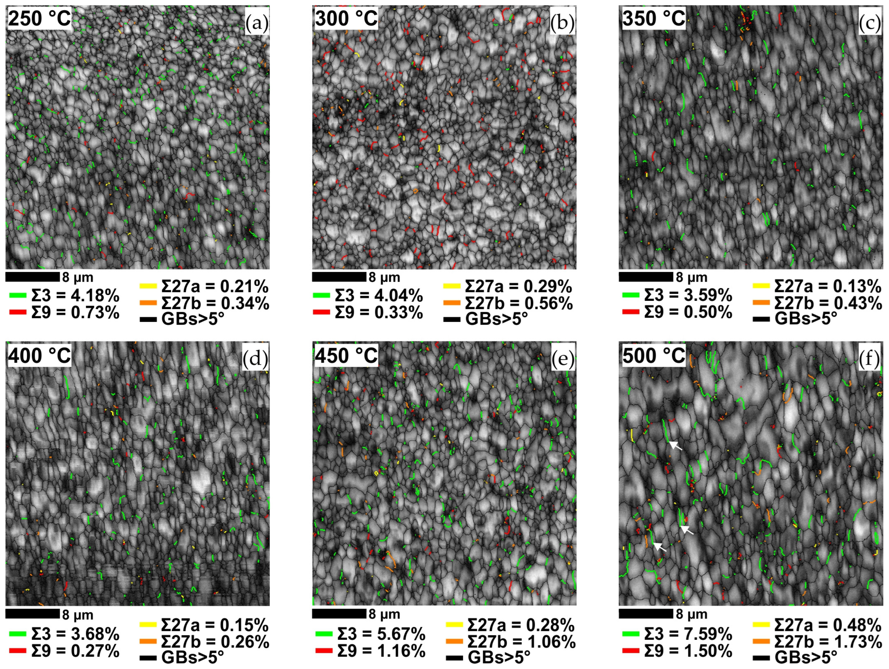
Figure 5 shows the CSL boundary map superimposed on the band contrast maps for the annealed samples. EBSD analysis revealed a moderate increase in the fraction of CSL-Σ3 boundaries to about 4% after annealing at temperatures up to 400 °C. Despite this increase, the volume fraction of Σ9, Σ27a, and Σ27b boundaries, which indicate the optimisation of the grain boundary structure, remained relatively low at around 1% in this temperature range. The population of the low-Σ-CSL GBs increased after annealing at 450 °C. Under these conditions, the Σ3 and Σ9 boundaries occupied volume fractions of 5.76% and 1.16%, respectively. The Σ27a and Σ27b boundaries showed a consistent trend and together accounted for 1.34%, similar to the Σ9 boundaries. Following Randle’s Σ3 regeneration model [31,32], it can be concluded that the Σ27 boundaries were generated by the Σ3 + Σ9 = Σ27 relationship. Consequently, the percentage of Σ27 boundaries appeared to be closely related to the population of Σ9 boundaries.
When the annealing temperature was further increased to 500 °C, more thermal activation energy was provided for recrystallisation, resulting in a higher percentage of special low-Σ-CSL GBs. Under these conditions, Σ3 and Σ9 boundaries accounted for 7.59% and 1.50%, respectively, while Σ27a and Σ27b boundaries contributed 0.48% and 1.73%, respectively. A noteworthy observation in this analysis was the distinctive well-defined and parallel-sided appearance of certain CSL-Σ3 boundaries, which is commonly associated with coherent twin boundaries formed during recrystallisation [33]. These boundaries are highlighted by white arrows in Figure 5f.
Additionally, it is crucial to highlight that the annealing twins (CSL Σ3 boundaries), follow a similar trend to HAGBs, as depicted in Figure 4f and Figure 5f. The notable increase in the population of HAGBs and annealing Σ3 twin boundaries within the alloy microstructure suggests that KoBo extrusion supplied ample activation energy for grain boundary migration. This, in turn, facilitated the GBE in LPBF AlSi10Mg alloy.
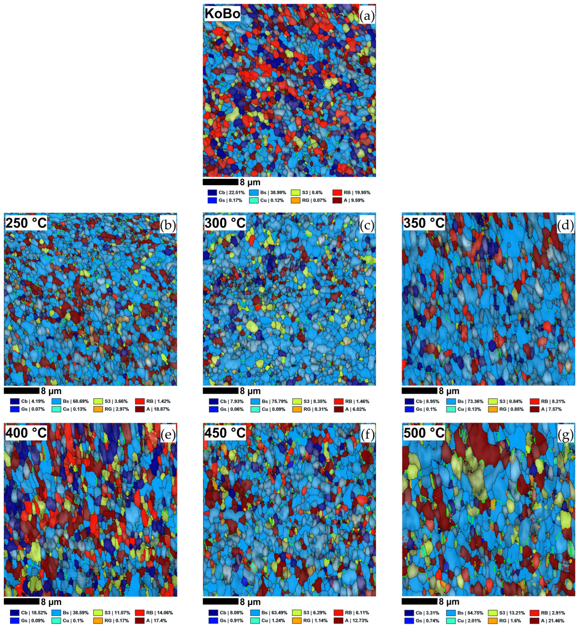
Figure 6 displays the special grain boundary maps superimposed on the texture component maps, and Table 2 summarises the results of the quantitative analysis.
The moderate temperature of ~280 °C during the extrusion process provided the conditions for the occurrence of dynamic recovery (DRV), dynamic recrystallisation (DRX), precipitation, and the formation of microtextures. For this reason, the main textural components identified in the KoBo-processed sample were cube, brass, and rotated brass orientations, as shown in Figure 6a. According to study [34], the cube texture is formed as a result of DRX, as this is a typical recrystallisation texture, whereas brass is a typical deformation texture that can occur due to the simultaneous presence of tensile and compressive stresses during the hot extrusion process [35]. It is worth mentioning that a similar texture was reported by Yang et al. [36], who found that in the extruded Al–Mg–Si alloy, the main textures were brass {110}<112> and recrystallisation cube {100}<001>.
With reference to the literature [37,38,39] and the microstructural observations in Figure 3, it can be assumed that the refined second phase precipitates acted as “strong pinning points” that caused a retarding force for recrystallisation, resulting in a larger population of the brass deformation texture.
After annealing at 250 °C, the fractions of individual texture components changed noticeably, as shown in Figure 6b. In this condition, brass-oriented grains dominated the microstructure and accounted for about 69% of the total texture. When the annealing temperature rose to 300 °C, the fraction of brass-oriented grains grew to 76%, as seen in Figure 6c. Additionally, more S-oriented grains emerged as part of the recrystallisation texture [40]. Further increasing the annealing temperature to 350 °C had no significant effect on the texture. According to data from Figure 6d, the brass-oriented grains in this condition constituted about 74% of the total grains.
After annealing at 400 °C, the dominant texture component was brass texture. It was also noticeable that some amount of brass texture transformed into the recrystallisation cube texture. Furthermore, S texture and rotated brass texture were clearly present in some grains, as displayed in Figure 6e. Annealing at 450 °C resulted in an enhancement of brass texture, which constituted about 63% of the total textures, as shown in Figure 6f. According to the literature [41,42], the enhancement of brass texture could be attributed to strain-induced boundary migration (SIBM). This was consistent with the texture component map showing the development of numerous CSL-Σ3 boundaries near the brass-oriented grains. This effect was more pronounced in the sample annealed at 500 °C, which had the highest fraction of CSL-Σ3 boundaries. As seen in Figure 6g, numerous CSL-Σ3 boundaries ranging from about 0.5 µm to 2.5 µm in length were located in close proximity to the brass-oriented grains.
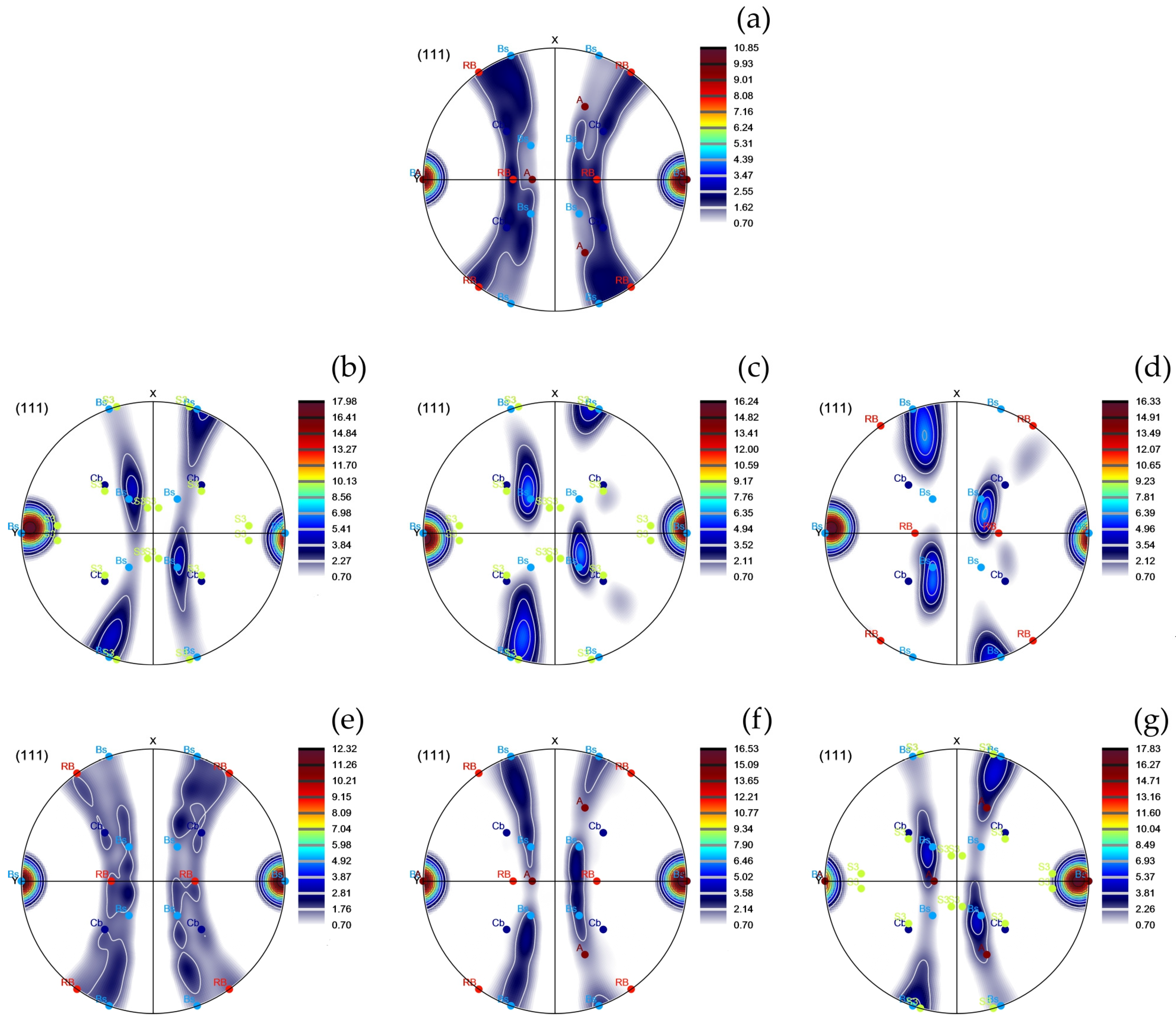
In order to analyse the textural components in detail, the (111) pole figures were plotted. It can be seen, in Figure 7, that all pole figures have similar characteristic textures that are typical of the extruded alloys. From Figure 7a, it can be noted that strong cube, brass, and rotated brass textures with a maximum intensity of 10.59 random levels (rl) developed in the KoBo-processed sample. According to the literature [43], the deformation at elevated temperature is favourable for the formation of the Bs texture, which might have formed due to the dynamic recovery or activation of non-octahedral slip systems during the extrusion process. Furthermore, the highly heterogeneous flow of the metal [44] and the relatively high plastic strain during KoBo extrusion could promote strain-induced boundary migration (SIBM), which is beneficial for the formation of a brass texture [45]. Furthermore, the precipitate drag effect can enhance SIBM. It has been revealed that incoherent precipitates with a high degree of misfit can increase the grain boundary energy and decrease the drag force [46], thus accelerating SIBM.
After annealing at 250 °C, the brass texture was strengthened. In this condition, recovery dominated; therefore, the intensity of the brass texture was significantly increased to 17.98 Rl, as seen in Figure 7b. Referring to the work of Huang et al. [47] the brass texture is very stable; therefore, the brass-oriented subgrains can easily survive during annealing processes, while the grains with other orientations tend to be more easily recovered.
When the alloy was annealed at 300 and 350 °C, a large number of small subgrains formed, as seen in Figure 7c,d, which promoted the occurrence of the polygonisation of the brass-oriented parent grains [48]; this resulted in an additional minor enhancement of brass texture, as seen in Figure 7c,d.
As the annealing temperature was further increased to 400 °C, as shown in Figure 7e, the brass texture partially evolved into cube {100}<001> texture [47,49], which indicated that the recrystallisation process had occurred to some extent. This agreed with the microstructural observation that revealed an increase in the average grain size. Furthermore, some amount of brass texture translated into the rotated brass texture.
The relative stability of the deformed brass grains to annealing is highlighted in an increase in the relative volume fraction of this texture component in the sample annealed at 450 °C, as shown in Figure 7f. This stability of the brass component is attributed to its ability to deform with very few slip systems so that it is less affected than other deformation components during recrystallisation [50]. Furthermore, as the annealing temperature increased, the growth advantage for recrystallised cube grains disappeared. Therefore, the percentage volume fraction of the cube decreased from 18.5 to 8.08 as the annealing temperature increased from 400 to 450 °C.
Annealing at 500 °C resulted in the overall texture intensity strengthening, with the maximum brass component intensity of 17.8 rl, as shown in Figure 7g. Furthermore, there was a gradual increase in {112}<110> α-fibre orientation; however, this texture component is reported to be the last to recrystallise and be replaced [51].
This article presents experimental results indicating that a distinctive distribution of grain boundary characteristics and microtextures can be achieved through the innovative strain-annealing approach, hinting at the material’s potential to exhibit unique properties. For example, a substantial volume fraction of brass texture, typically formed during cold rolling or shear deformation, was proved to be advantageous in enhancing the strength and fatigue resistance of aluminium alloys [52]. However, given its relatively rigid orientation, it has a minimal impact on ductility [53]. On the contrary, the cube texture enhances the ductility and formability of the alloy but at the expense of reduced strength [54].
By carefully controlling the distribution of grain boundary properties, it is also possible to develop a complex microstructure that aids in the recombination or annihilation of point defects caused by irradiation [55]. This control also helps to prevent the harmful segregation of elements crucial for the chemical and mechanical stability of the alloy [56]. Research into the structure of grain boundaries has shown that low-energy grain boundaries, particularly low ΣCSL grain boundaries (special grain boundaries), exhibit strong resistance to intergranular corrosion [57]. In addition, the presence of these grain boundaries in the microstructure contributes to increased resistance to creep and stress corrosion cracking [10].

4. Conclusions

Based on the microstructural observations presented in this study, the main conclusions can be formulated as follows:
  • KoBo extrusion caused a significant grain refinement of LPBF AlSi10Mg alloy, resulting in a fine-grained microstructure with an average grain size of about 0.8 µm.
  • The ultra-fine-grained microstructure produced by KoBo extrusion was preserved after annealing up to 500 °C.
  • In the as-printed AlSi10Mg sample, the in situ-formed CSL boundaries accounted for about of 7% of the total boundary fraction.
  • The grain boundary character distribution in LPBF AlSI10Mg alloy was optimised in the KoBo extrusion followed by annealing at 500 °C. After this thermomechanical treatment, the population of Σ3, Σ9 and Σ27 was increased to about 11%.
  • Strain-induced boundary migration (SIBM) as well as the nucleation of twin boundaries promoted the formation of a strong brass texture in the KoBo-processed samples subjected to recrystallisation annealing.
In summary, the KoBo-extrusion process imparts a significant amount of strain to the LPBF AlSi10Mg alloy, making the strain-annealing approach effective in improving the CSL boundary fraction. Our research demonstrates that elevated annealing temperatures accelerate recrystallisation, leading to a higher density of CSL boundaries. The LPBF AlSi10Mg alloy, with its unique microstructure achieved through the presented thermomechanical treatment, holds great promise for aerospace and nuclear applications. The increased presence of low-CSL boundaries mitigates radiation-induced defects by promoting more stable grain boundaries, reducing the susceptibility of the material to radiation damage, and ultimately improving its overall resistance to the radiation environment.

Funding

The research was funded by the National Science Centre, Poland, based on decision number 2021/43/D/ST8/01946.

Data Availability Statement

Author agree to make data and materials supporting the results or analyses presented in their paper available upon reasonable request.

Conflicts of Interest

The author declares no conflict of interest.

References

  1. Watanabe, T. An approach to grain boundary design for strong and ductile polycrystals. Res. Mech. 1984, 11, 47–84. [Google Scholar]
  2. Cao, W.; Xia, S.; Bai, Q.; Zhang, W.; Zhou, B.; Li, Z.; Jiang, L. Effects of initial microstructure on the grain boundary network during grain boundary engineering in Hastelloy N alloy. J. Alloys Compd. 2017, 704, 724–733. [Google Scholar] [CrossRef]
  3. Guan, X.J.; Shi, F.; Ji, H.M.; Li, X.W. A possibility to synchronously improve the high-temperature strength and ductility in face-centered cubic metals through grain boundary engineering. Scr. Mater. 2020, 187, 216–220. [Google Scholar] [CrossRef]
  4. Yang, X.; Wang, P.; Huang, M. Grain boundary evolution during low-strain grain boundary engineering achieved by strain-induced boundary migration in pure copper. Mater. Sci. Eng. A 2022, 833, 142532. [Google Scholar] [CrossRef]
  5. McCarley, J.; Helmink, R.; Goetz, R.; Tin, S. Grain Boundary Engineering of a Low Stacking Fault Energy Ni-based Superalloy. Metall. Mater. Trans. A 2017, 48, 1666–1677. [Google Scholar] [CrossRef]
  6. Palaparti, D.P.R.; Vijayanand, V.D.; Mariappan, K.; Reddy, G.V.P. Correction: Correlating CSL Evolution and Strain Energy in Single Step Grain Boundary Engineered Austenitic Stainless Steel. Metall. Mater. Trans. A 2023, 54, 2506. [Google Scholar] [CrossRef]
  7. Ogawa, Y. Temperature-sensitive ductilization in hydrogen-alloyed Fe-Cr-Ni austenitic steel by enhanced deformation twinning. Scr. Mater. 2024, 238, 115760. [Google Scholar] [CrossRef]
  8. Dammu, S.; Singh, A.P.; Lala, S.R.F.; Srivastava, C. Grain Boundary Engineering in Electrodeposited Tin-Carbon Nanotube Composite Coatings for Enhanced Corrosion Resistance Performance. Metall. Mater. Trans. A 2023, 54, 3928–3939. [Google Scholar] [CrossRef]
  9. Chen, X.-H.; Wang, F.; Zhang, F. Grain boundary engineering process for nano reinforced aluminum matrix composites. J. Alloys Compd. 2023, 939, 168834. [Google Scholar] [CrossRef]
  10. Shamanian, M.; Mostaan, H.; Safari, M.; Szpunar, J.A. EBSD Study on Grain Boundary and Microtexture Evolutions During Friction Stir Processing of A413 Cast Aluminum Alloy. J. Mater. Eng. Perform. 2016, 25, 2824–2835. [Google Scholar] [CrossRef]
  11. Jia, H.; Jin, S.; Li, Y. Formation of Σ3{110} incoherent twin boundaries through geometrically necessary boundaries in an Al-8Zn alloy subjected to one pass of equal channel angular pressing. J. Alloys Compd. 2018, 762, 190–195. [Google Scholar] [CrossRef]
  12. Pradeep, S.; Jain, V.K.S.; Muthukumaran, S.; Kumar, R. Microstructure and texture evolution during multi-pass friction stir processed AA5083. Mater. Lett. 2021, 288, 129382. [Google Scholar] [CrossRef]
  13. Liu, B.; Ding, Y.; Xu, J.; Gao, Y.; Chu, C.; Hu, Y.; Chen, D. Grain boundary engineering activated by residual stress during the laser powder bed fusion of Inconel 718 and the electrochemical corrosion performance. Mater. Charact. 2023, 204, 113160. [Google Scholar] [CrossRef]
  14. Dong, X.; Zhou, Y.; Qu, Y.; Wu, M.; Sun, Q.; Shi, H.; Peng, H.; Zhang, Y.; Xu, S.; Li, N.; et al. Recrystallization behavior and grain boundary character evolution in Co-Cr alloy from selective laser melting to heat treatment. Mater. Charact. 2022, 185, 111716. [Google Scholar] [CrossRef]
  15. Tokita, S.; Kokawa, H.; Kodama, S.; Sato, Y.S.; Sano, Y.; Li, Z.; Feng, K.; Wu, Y. Suppression of intergranular corrosion by surface grain boundary engineering of 304 austenitic stainless steel using laser peening plus annealing. Mater. Today Commun. 2020, 25, 101572. [Google Scholar] [CrossRef]
  16. Snopiński, P.; Matus, K.; Łagoda, M.; Appiah, A.N.S.; Hajnyš, J. Engineering an ultra-fine grained microstructure, twins and stacking faults in PBF-LB/M Al-Si alloy via KoBo extrusion method. J. Alloys Compd. 2024, 970, 172576. [Google Scholar] [CrossRef]
  17. Korbel, A.; Błaż, L.; Bochniak, W.; Pawlyta, M.; Ostachowski, P.; Łagoda, M. Nano-Dimensional Elements in the Structure of Zinc Subjected to KOBO Extrusion. Metallogr. Microstruct. Anal. 2023, 12, 427–432. [Google Scholar] [CrossRef]
  18. Dobkowska, A.; Zielińska, A.; Paulin, I.; Donik, Č.; Łojkowski, M.; Koralnik, M.; Adamczyk-Cieslak, B.; Paradowski, K.; Tkocz, M.; Kuc, D.; et al. Microstructure and properties of an AZ61 alloy after extrusion with a forward-backward oscillating die without preheating of the initial billet. J. Alloys Compd. 2023, 952, 169843. [Google Scholar] [CrossRef]
  19. Liu, S.; Wang, Y.; Yarigarravesh, M.; Tayyebi, M.; Tayebi, M. Evaluation of whisker alignment and anisotropic mechanical properties of ZK60 alloy reinforced with SiCw during KOBO extrusion method. J. Manuf. Process. 2022, 84, 344–356. [Google Scholar] [CrossRef]
  20. Snopiński, P.; Matus, K. Characterisation of Microstructure and Special Grain Boundaries in LPBF AlSi10Mg Alloy Subjected to the KoBo Extrusion Process. Symmetry 2023, 15, 1634. [Google Scholar] [CrossRef]
  21. Snopiński, P.; Woźniak, A.; Łukowiec, D.; Matus, K.; Tański, T.; Rusz, S.; Hilšer, O. Evolution of Microstructure, Texture and Corrosion Properties of Additively Manufactured AlSi10Mg Alloy Subjected to Equal Channel Angular Pressing (ECAP). Symmetry 2022, 14, 674. [Google Scholar] [CrossRef]
  22. Korbel, A.; Bochniak, W.; Ostachowski, P.; Błaż, L. Visco-Plastic Flow of Metal in Dynamic Conditions of Complex Strain Scheme. Metall. Mater. Trans. A 2011, 42, 2881–2897. [Google Scholar] [CrossRef]
  23. Jodi, D.E.; Kitashima, T.; Singh, A.; Watanabe, M. High-temperature microstructural stability of pure Ni fabricated by laser powder bed fusion using Gaussian and flat-top beam profiles. Mater. Charact. 2023, 200, 112897. [Google Scholar] [CrossRef]
  24. Xue, S.; Kuo, W.; Li, Q.; Fan, Z.; Ding, J.; Su, R.; Wang, H.; Zhang, X. Texture-directed twin formation propensity in Al with high stacking fault energy. Acta Mater. 2018, 144, 226–234. [Google Scholar] [CrossRef]
  25. Zhu, Z.; Li, W.; Nguyen, Q.B.; An, X.; Lu, W.; Li, Z.; Ng, F.L.; Nai, S.M.L.; Wei, J. Enhanced strength–ductility synergy and transformation-induced plasticity of the selective laser melting fabricated 304L stainless steel. Addit. Manuf. 2020, 35, 101300. [Google Scholar] [CrossRef]
  26. Monier, L.; Buttard, M.; Veron, M.; Blandin, J.-J.; Martin, G.; Villaret, F.; Shen, Y.; Yrieix, B.; Ernould, C.; Guyon, J.; et al. On the origin of grain refinement and twin boundaries in as-fabricated austenitic stainless steels produced by laser powder bed fusion. Addit. Manuf. 2023, 61, 103351. [Google Scholar] [CrossRef]
  27. Brandon, D.G. The structure of high-angle grain boundaries. Acta Metall. 1966, 14, 1479–1484. [Google Scholar] [CrossRef]
  28. Fang, Z.; Xiao, J.; Tan, S.; Deng, C.; Wang, G.; Mao, S.X. Atomic-scale observation of dynamic grain boundary structural transformation during shear-mediated migration. Sci. Adv. 2023, 8, eabn3785. [Google Scholar] [CrossRef]
  29. Illgen, C.; Bohne, B.; Wagner, M.F.-X.; Frint, P. Thermal stability of SPD-processed aluminum alloys—Internal friction as an indication for recovery, recrystallization and abnormal grain growth. J. Mater. Res. Technol. 2022, 17, 1752–1759. [Google Scholar] [CrossRef]
  30. Doherty, R.D. The Deformed State and Nucleation of Recrystallization. Met. Sci. 1974, 8, 132–142. [Google Scholar] [CrossRef]
  31. Randle, V.; Hu, Y. The role of vicinal Σ3 boundaries and Σ9 boundaries in grain boundary engineering. J. Mater. Sci. 2005, 40, 3243–3246. [Google Scholar] [CrossRef]
  32. Randle, V. Twinning-related grain boundary engineering. Acta Mater. 2004, 52, 4067–4081. [Google Scholar] [CrossRef]
  33. Laleh, M.; Hughes, A.E.; Tan, M.Y.; Rohrer, G.S.; Primig, S.; Haghdadi, N. Grain boundary character distribution in an additively manufactured austenitic stainless steel. Scr. Mater. 2021, 192, 115–119. [Google Scholar] [CrossRef]
  34. Goli, F.; Jamaati, R. Significant Texture Weakening of Al-Cu-Mg Alloy by Low Strain Asymmetric Cross Rolling Process. J. Mater. Eng. Perform. 2023, 32, 5576–5582. [Google Scholar] [CrossRef]
  35. Li, Z.; Chen, L.; Zhang, X.; Zhao, G.; Zhang, C. Strengthening mechanism and anisotropy of mechanical properties of Si3N4p/Al-Mg-Si composites fabricated by sintering and extrusion. Mater. Des. 2021, 210, 110111. [Google Scholar] [CrossRef]
  36. Yang, W.; Ji, S.; Li, Z.; Wang, M. Grain boundary precipitation induced by grain crystallographic misorientations in an extruded Al–Mg–Si–Cu alloy. J. Alloys Compd. 2015, 624, 27–30. [Google Scholar] [CrossRef]
  37. Xiao, Z.; Yang, X.; Wang, J.; Fang, Z.; Guo, C.; Zhang, D.; Yang, Y.; Zhang, X. Influence of Fe addition on annealing behaviors of a phosphorus containing brass. J. Alloys Compd. 2017, 712, 268–276. [Google Scholar] [CrossRef]
  38. Bo, G.; Jiang, F.; Dong, Z.; Wang, G.; Zhang, H. Revealing the influence of pre-precipitation microstructure on hot workability in an Al-Cu-Mg-Zr alloy. Mater. Sci. Eng. A 2019, 755, 147–157. [Google Scholar] [CrossRef]
  39. Li, X.; Cui, X.; Liu, H.; Zhu, Z.; Liu, J.; Zhang, X.; Cui, H.; Li, H.; Pan, Y.; Feng, R.; et al. Study on the improvement and mechanism of AA6101 electrical conductivity by trace TM (Zr, V, Ti) elements-assisted boron treatment. J. Alloys Compd. 2023, 939, 168728. [Google Scholar] [CrossRef]
  40. Hjelen, J.; Ørsund, R.; Nes, E. On the origin of recrystallization textures in aluminium. Acta Metall. Mater. 1991, 39, 1377–1404. [Google Scholar] [CrossRef]
  41. Zhao, Q.; Liu, Z. Texture Evolution of Hot Rolled Al–Cu–Mg–Zr Alloy During Annealing. Met. Mater. Int. 2022, 28, 2947–2961. [Google Scholar] [CrossRef]
  42. Wang, X.; Xiong, W.; Zheng, Y.; Zhang, J. The Correlation between Texture Evolution and Recrystallization Behavior during Rheologic Forming of 2195 Al–Li Alloy Cylindric Shell. Metals 2023, 13, 853. [Google Scholar] [CrossRef]
  43. Li, S.; Zhao, Q.; Liu, Z.; Li, F. A Review of Texture Evolution Mechanisms During Deformation by Rolling in Aluminum Alloys. J. Mater. Eng. Perform. 2018, 27, 3350–3373. [Google Scholar] [CrossRef]
  44. Gusak, A.; Danielewski, M.; Korbel, A.; Bochniak, M.; Storozhuk, N. Elementary model of severe plastic deformation by KoBo process. J. Appl. Phys. 2014, 115, 34905. [Google Scholar] [CrossRef]
  45. Bate, P.S.; Huang, Y.; Humphreys, F.J. Development of the “brass” texture component during the hot deformation of Al–6Cu–0.4Zr. Acta Mater. 2004, 52, 4281–4289. [Google Scholar] [CrossRef]
  46. Ihara, K.; Miura, Y. Dynamic recrystallization in Al-Mg-Sc alloys. Mater. Sci. Eng. A 2004, 387–389, 647–650. [Google Scholar] [CrossRef]
  47. Huang, T.; Liu, F.; Liu, Z.; He, G. Evolution of Microstructure, Texture, and Hardness in an Al-Cu-Mg Alloy during Annealing. J. Mater. Eng. Perform. 2022, 31, 1419–1431. [Google Scholar] [CrossRef]
  48. Humphreys, F.J.; Hatherly, M. Chapter 12—Recrystallization Textures. In Hatherly MBT-R and RAP, 2nd ed.; Humphreys FJ, Ed.; Elsevier: Oxford, UK, 2004; pp. 379–413. [Google Scholar] [CrossRef]
  49. Zhao, Q.; Liu, Z.; Li, S.; Huang, T.; Xia, P.; Lu, L. Evolution of the Brass texture in an Al-Cu-Mg alloy during hot rolling. J. Alloys Compd. 2017, 691, 786–799. [Google Scholar] [CrossRef]
  50. Alvi, M.H.; Cheong, S.W.; Suni, J.P.; Weiland, H.; Rollett, A.D. Cube texture in hot-rolled aluminum alloy 1050 (AA1050)—Nucleation and growth behavior. Acta Mater. 2008, 56, 3098–3108. [Google Scholar] [CrossRef]
  51. Shen, F.; Zhou, Z.; Li, W.; Sun, Z.; Tian, J.; Xie, C.; Guo, J.; Liao, Z.; Yi, D.; Zhang, J.; et al. Micro-mechanism of texture evolution during isochronal annealing of as-annealed hot rolled Al-Cu-Mg sheet. Mater. Des. 2019, 165, 107575. [Google Scholar] [CrossRef]
  52. Shen, F.; Yi, D.; Wang, B.; Liu, H.; Jiang, Y.; Tang, C.; Jiang, B. Semi-quantitative evaluation of texture components and anisotropy of the yield strength in 2524 T3 alloy sheets. Mater. Sci. Eng. A 2016, 675, 386–395. [Google Scholar] [CrossRef]
  53. Zhou, W.; Huo, Q.; Wang, C.; Zhang, Y.; Zhang, Z.; Hu, S.; Zhao, S.; Nagaumi, H.; Yang, X. Effects of texture component, dislocation evolution and precipitation on the creep resistance of T5-treated Al-Mg-Si alloy with different Cu contents. Mater. Charact. 2022, 189, 111981. [Google Scholar] [CrossRef]
  54. Hirsch, J.; Al-Samman, T. Superior light metals by texture engineering: Optimized aluminum and magnesium alloys for automotive applications. Acta Mater. 2013, 61, 818–843. [Google Scholar] [CrossRef]
  55. Sakaguchi, N.; Endo, M.; Watanabe, S.; Kinoshita, H.; Yamashita, S.; Kokawa, H. Radiation-induced segregation and corrosion behavior on Σ3 coincidence site lattice and random grain boundaries in proton-irradiated type-316L austenitic stainless steel. J. Nucl. Mater. 2013, 434, 65–71. [Google Scholar] [CrossRef]
  56. Barnard, L.; Barr, C.M.; Hattar, K.; Morgan, D.; Nathaniel, J.E.; Szlurfarska, I.; Morgan, D.; Taheri, M.L. Grain boundary character dependence of radiation-induced segregation in a model Ni–Cr alloy. J. Mater. Res. 2015, 30, 1290–1299. [Google Scholar] [CrossRef]
  57. Hu, Y.; Bai, Q.; Xia, S.; Liu, K.; He, Q.; Xu, G. Applying Grain Boundary Engineering and Stabilizing Heat Treatment to 321 Stainless Steel for Enhancing Intergranular Corrosion Resistance. J. Mater. Eng. Perform. 2023. [Google Scholar] [CrossRef]
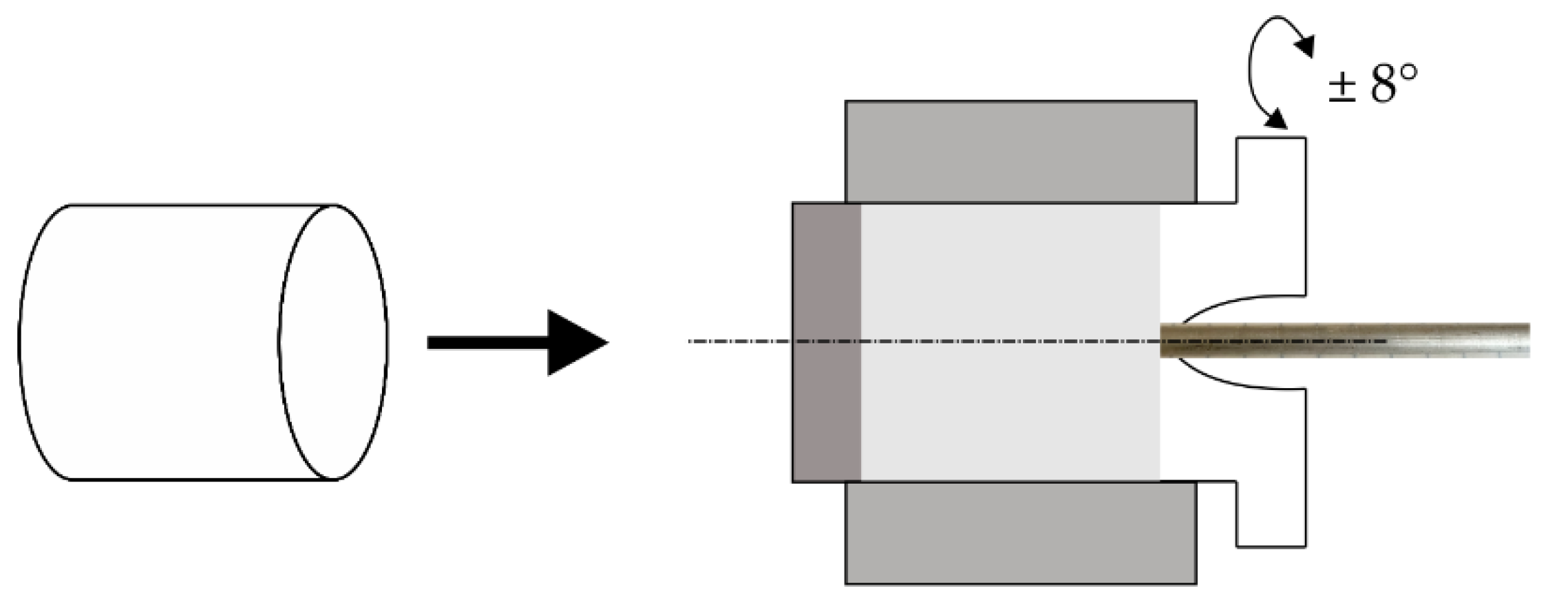
Figure 1. Schematic illustration of the KoBo-extrusion process.
Symmetry 16 00122 g001
Figure 2. EBSD maps of the LPBF AlSi10Mg alloy. (a) IPF-Z map taken on the X–Y plane; (b) band contrast map taken on the X–Y plane; (c) texture component map with superimposed special grain boundaries taken on the X-Y plane; (d) IPF-Z map taken on the X–Z plane; (e) band contrast map taken on the X–Z plane; and (f) texture component map with superimposed special grain boundaries taken on the X–Z plane.
Symmetry 16 00122 g002
Figure 3. Microstructures of the KoBo-processed LPBF AlSi10Mg alloy sample. (a) IPF-Z image; (b) band contrast map; (c) EBDS TKD band contrast map; (d) EBSD TKD IPF-Y map; (e) bright field TEM image; (f) HRTEM image of the boundary area highlighted by a yellow square in (e)—note that the TEM foil was oriented with the aim of revealing the atomic arrangement of grain labelled as (1); (g) HRTEM image of the boundary area highlighted by a yellow square in (e)—note that the TEM foil was oriented with the aim of revealing the atomic arrangement of grain labelled as (2); (h) FFT of the boundary labelled as (1) in (e); (i) FFT of the boundary labelled as (2) in (e); and (j) simulated atomic arrangement of the boundary area confirming the CSL Σ3 boundary.
Symmetry 16 00122 g003
Figure 4. IPF-Z maps of the KoBo-processed samples (a) annealed at 250 °C for 1 h, (b) annealed at 300 °C for 1 h, (c) annealed at 350 °C for 1 h, (d) annealed at 400 °C for 1 h, (e) annealed at 450 °C for 1 h, or (f) annealed at 500 °C for 1 h.
Symmetry 16 00122 g004
Figure 5. CSL boundary maps superimposed on band contrast maps for KoBo-processed samples (a) annealed at 250 °C for 1 h, (b) annealed at 300 °C for 1 h, (c) annealed at 350 °C for 1 h, (d) annealed at 400 °C for 1 h, (e) annealed at 450 °C for 1 h, or (f) annealed at 500 °C for 1 h.
Symmetry 16 00122 g005
Figure 6. Texture components map with superimposed special grain boundaries for KoBo-processed and annealed samples. The colour coding is shown below the maps. (a) Kobo-processed, (b) annealed at 250 °C for 1 h, (c) annealed at 300 °C for 1 h, (d) annealed at 350 °C for 1 h, (e) annealed at 400 °C for 1 h, (f) annealed at 450 °C for 1 h, or (g) annealed at 500 °C for 1 h.
Symmetry 16 00122 g006
Figure 7. The (111) pole figures of the KoBo-processed and annealed samples. (a) Kobo-processed, (b) annealed at 250 °C for 1 h, (c) annealed at 300 °C for 1 h, (d) annealed at 350 °C for 1 h, (e) annealed at 400 °C for 1 h, (f) annealed at 450 °C for 1 h, or (g) annealed at 500 °C for 1 h.
Symmetry 16 00122 g007
Table 1. Texture characteristics of the LPBF AlSi10Mg sample analysed using EBSD.
Texture ComponentCube {001}<100> (%)Goss {011}<100> (%)Brass {110}<112> (%)Copper {112}<111> (%)S {123}<634>
(%)
Rotated Goss (RG) {011}<011>
(%)
Rotated Brass (RB) {110}<556> (%)A
{110}<111>
(%)
X–Y plane26.757.915.318.5715.5127.555.343.06
X–Z plane38.518.644.385.4819.076.2413.664.02
Table 2. Texture characteristics of the KoBo-processed and annealed AlSi10Mg samples. The values in the table correspond to the texture map shown in Figure 5.
Texture ComponentCube {001}<100> (%)Goss {011}<100> (%)Brass {110}<112> (%)Copper {112}<111> (%)S {123}<634>
(%)
R. Goss (RG) {011}<011>
(%)
R. Brass (RB) {110}<556> (%)A
{112}<110>
(%)
KoBo22.510.1738.990.128.60.0719.959.59
Annealed at 250 °C4.190.0768.690.133.662.971.4218.87
Annealed at 300 °C7.930.0675.790.098.350.311.466.02
Annealed at 350 °C8.950.173.360.130.840.858.217.57
Annealed at 400 °C18.520.0938.590.111.070.1714.0617.4
Annealed at 450 °C8.080.9163.491.246.291.146.1112.73
Annealed at 500 °C3.310.7454.752.0113.211.62.9121.46
Disclaimer/Publisher’s Note: The statements, opinions and data contained in all publications are solely those of the individual author(s) and contributor(s) and not of MDPI and/or the editor(s). MDPI and/or the editor(s) disclaim responsibility for any injury to people or property resulting from any ideas, methods, instructions or products referred to in the content.